Table of Contents
Advertisement
Quick Links
Advertisement
Table of Contents
Troubleshooting

Related Manuals for Ultrasonix SonixMDP


Summary of Contents for Ultrasonix SonixMDP
- Page 1 SonixMDP/SP/OP Ultrasound System Service Manual...
- Page 3 1.778.296.3860 (Support) © 2013 Ultrasonix Medical Corporation 00.053.101, Revision C, March 27, 2013 All Rights Reserved. Printed in Canada. US Patents 6,216,029 - 6,325,759 - 6,558,326 - 6,911,008 - 7,274,325 - 8,088,070 - D654,178 SonixMDP/SP/OP Service Manual 00.053.101, Revision C...
-
Page 5: Table Of Contents
3.3.3 Powering the System .................................... 3-16 3.3.3.1 Turning on Main Power Switch................................ 3-16 3.3.3.2 Changing Fuses ....................................3-17 3.3.4 UPS Configuration (SonixMDP and SonixSP only) ..........................3-18 3.3.5 Transducer Inspection ..................................3-20 3.3.6 System Initialization ....................................3-20 3.3.7 Peripherals......................................3-21 3.3.7.1... - Page 6 Reinstalling the Front Block/Ultrasound Module............................7-33 7.5.5 Closing the Front Block/Ultrasound Module ............................7-36 MODULO – INTERNAL COMPONENT REPLACEMENT..........................7-37 7.6.1 Removing the Hard Drives..................................7-37 7.6.2 Replacing the CPU Fan ..................................7-39 7.6.3 Replacing/Reseating Cards ...................................7-40 Table of Contents 00.053.101, Revision C SonixMDP/SP/OP Service Manual...
- Page 7 11.2.7 Transducer Holders and Cable Hooks ..............................11-4 11.2.8 Peripheral Tray and Basket ..................................11-4 11.2.9 SonixGPS™......................................11-4 11.2.10 System Filter ......................................11-5 11.2.10.1Cleaning the System Filter ................................11-5 11.2.10.2Cleaning the Cleaning Modulo Fan and Exhaust Filters ........................11-6 11.2.11 Fans ........................................11-7 SonixMDP/SP/OP Service Manual 00.053.101, Revision C Table of Contents...
- Page 8 12.12 LCD DISPLAY BLANK, TOUCH SCREEN DISPLAYS CORRECTLY ......................12-4 12.13 LCD DISPLAY BLANK, TOUCH SCREEN DISPLAYS ULTRASONIX LOGO ONLY ..................12-4 12.14 LCD DISPLAY WORKS, BUT TOUCH SCREEN STILL DISPLAYS ULTRASONIX LOGO EVEN IN IMAGING MODE......12-4 12.15 SYSTEM DOES NOT BOOT, ERROR DISPLAYED ON LCD DISPLAY.....................12-5 12.16 INITIALIZATION FAILURES..................................12-5...
- Page 9 A.10.1 Check Trackball and Mouse Port Connections ............................A-7 A.10.2 Check for Interference from a USB Device............................. A-7 A.11 LCD DISPLAY WORKS, BUT TOUCH SCREEN STILL DISPLAYS ULTRASONIX LOGO EVEN IN IMAGING MODE......A-8 A.11.1 Check the Serial Cable Connection ................................ A-8 A.11.2 Check the Serial Expansion Card Driver ..............................
- Page 10 Table of Contents 00.053.101, Revision C SonixMDP/SP/OP Service Manual...
- Page 11 Console Mount (Including Tilt and Swivel) ..............................D-8 Side Shroud Removal ....................................D-9 Modulo Removal ......................................D-10 Front Block Removal ....................................D-11 ECG Module Removal/Replacement ................................D-12 UPS Removal .......................................D-13 UPS Battery Removal ....................................D-14 Wheel Replacement .....................................D-15 Filter Removal/Replacement ..................................D-16 SonixMDP/SP/OP Service Manual 00.053.101, Revision C List of Service Drawings...
- Page 12 List of Service Drawings 00.053.101, Revision C SonixMDP/SP/OP Service Manual...
-
Page 13: Chapter 1: General Information
It is the user's responsibility to ensure the system is used only under the electrical conditions dictated by Ultrasonix Medical Corp. Failure to comply with these conditions may result in damage to the system which is not covered by the Ultrasonix warranty. -
Page 14: License Agreement
Ultrasonix, or its suppliers, retain(s) ownership of and title to any computer program supplied with the Equipment and to the trade secrets embodied in such computer programs. Subject to the Buyer’s acceptance and fulfillment of the obligations in... -
Page 15: System Overview
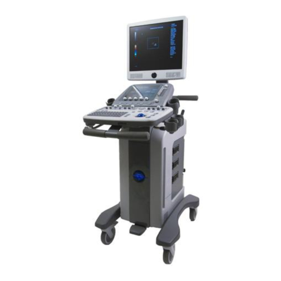
SYSTEM OVERVIEW The SonixMDP/SP/OP Ultrasound System is a software driven, ergonomic, diagnostic medical device. It uses state of the art technologies to acquire, process and display ultrasound data (Figure 1-1). The system has several major field serviceable components including: LCD display with built-in speakers and a multi- position, articulated lift system, operator console, modulo, transducers and UPS. -
Page 16: Physical Description
– are encased in an aircraft grade aluminum composite case for ease of service. 1.9.4 Transducers Ultrasonix offers a wide selection of high performance transducers for a variety of imaging applications. Incorporating the latest acoustic materials and technology, these lightweight transducers are ergonomic and durable for maximum clinical use. Refer to 6.2.1 Transducers... -
Page 17: Chapter 2: System Specifications
152.5 cm 60 in Height, lowest position (measured from top of LCD display to floor) 137 cm 54 in Weight (with UPS and battery) (SonixMDP and Sonix SP only) 102 kg 225 lbs Weight (without UPS and battery) 77 kg... - Page 18 Ghana..........220V Norway ..........220V Zambia ..........220V Gibraltar........... 220V Okinawa ...........110V Zimbabwe........220V Caution: Ensure the correct voltage rating has been selected before turning system ON. Contact an Ultrasonix Technical Support Representative if the appropriate voltage rating is not listed here (Table 2-4, above).
-
Page 19: Chapter 3: System Installation
Warning: Operate in an indoor environment only, free from moisture, flammable liquids, gases, corrosive substances, strong electrical or magnetic fields and equipment that generates high frequency waves. Ultrasonix cannot guarantee the proper performance of the system if used in the above-listed conditions. Table 3-2: Barcode Reader Operating Temperature 32º... -
Page 20: Electrical Requirements
100-120V ~, 50/60Hz CSA & UL approved 250Vac, 15A, 3 wire, 18 AWG, grounding type, 6-15P Hospital Grade plug cap, less than 6 m long, 200-240V~, 50/60Hz CSA & UL approved Chapter 3: System Installation 00.053.101, Revision C SonixMDP/SP/OP Service Manual... -
Page 21: Electrostatic Discharge
Warning: The system should not be used adjacent to or stacked with other equipment. If adjacent or stacked use is necessary, the system should be observed in order to verify normal operation in the configuration in which it will be used. SonixMDP/SP/OP Service Manual 00.053.101, Revision C Chapter 3: System Installation... -
Page 22: Wiring Requirements
Caution: System networking options are intended for use inside your organization's firewall. Organizations that elect to configure/use the networking functionality provided by Ultrasonix are assuming all liabilities and risks associated with that decision. 3.1.5.3 Image Management Network Obtain the following information from the system administrator: •... -
Page 23: Pre-Installation
Examine the "Tip and Tell" attachment on the outside of the package to ensure the crate has not been tipped too far during transport and delivery. "Tip and Tell" = Acceptable "Tip and Tell" = Unacceptable Report any damage to both the carrier and Ultrasonix. SonixMDP/SP/OP Service Manual 00.053.101, Revision C Chapter 3: System Installation... -
Page 24: Sonixmdp/Sp/Op Uncrating Instructions
Lift off the plastic bag covering the system. Note: Do not cut the bag. As the edges are simply tucked into the box at the base of the system it can be easily removed. Chapter 3: System Installation 00.053.101, Revision C SonixMDP/SP/OP Service Manual... - Page 25 Remove the paperwork from beneath the rear of the console. Remove the foam packing from the rear of the system, as well as any biopsy kits that were packed below this foam. SonixMDP/SP/OP Service Manual 00.053.101, Revision C Chapter 3: System Installation...
- Page 26 Slice the tape in the center of the foam at the rear of the system then remove the foam, bending it open to clear the rear pull handles. Remove any transducer boxes or Biopsy kits from the rear of the system. Remove any transducer boxes packed at the front/sides of the system. Chapter 3: System Installation 00.053.101, Revision C SonixMDP/SP/OP Service Manual...
- Page 27 Gently remove the foam packing from the sides of the system. Remove the foam from around the front wheelbase. Undo the back cardboard flap and remove the foam from the rear of the system. SonixMDP/SP/OP Service Manual 00.053.101, Revision C Chapter 3: System Installation...
- Page 28 With one person standing behind the system, tip the system back so the front wheels clear the foam depressions. A second person should place the two (2) triangular foam blocks into the foam depressions to create a level surface under the front of the system. Chapter 3: System Installation 00.053.101, Revision C SonixMDP/SP/OP Service Manual 3-10...
- Page 29 13) under the front cardboard flap, taking care to center the ramp on each wheel. From the rear, lift/roll them the system clear of the rear depressions in the packing foam. Push the system down the ramps and off the palette. SonixMDP/SP/OP Service Manual 00.053.101, Revision C Chapter 3: System Installation 3-11...
-
Page 30: Installation
Tip the LCD display up and ensure that it: • tips forward and back as desired • rotates from side to side • stays firmly in position once the required angle and rotation is achieved. Chapter 3: System Installation 00.053.101, Revision C SonixMDP/SP/OP Service Manual 3-12... -
Page 31: Console Height, Angle And Swivel Adjustment
Use the front pull handles to gently rock the console forward or backward until the desired tilt is achieved. Pull backward on the lever under the right side of the console to lock the console in place. SonixMDP/SP/OP Service Manual 00.053.101, Revision C Chapter 3: System Installation... -
Page 32: Emi Filter And Power Panel
Caution: The system voltage setting is configured in the factory. It should not need to be changed in the field. Figure 3-2: EMI Filter Figure 3-3: EMI Filter and System Power Button Location Main Power Switch AC Power Cord Receptacle Chapter 3: System Installation 00.053.101, Revision C SonixMDP/SP/OP Service Manual 3-14... - Page 33 Position the screwdriver at the top (as in step 2), using it to remove the fuse box. Flip the fuse box and reinsert it so the correct voltage is visible. Close the fuse box lid. SonixMDP/SP/OP Service Manual 00.053.101, Revision C Chapter 3: System Installation 3-15...
-
Page 34: Powering The System
Caution: DO NOT use Main Power switch for regular power shut downs. Failure to follow the correct procedure may result in loss of patient data and/or hard drive failure. Chapter 3: System Installation 00.053.101, Revision C SonixMDP/SP/OP Service Manual 3-16... -
Page 35: Changing Fuses
Replace one or both fuses, as required. Reinsert the fuse box. Caution: Ensure the correct voltage setting is visible and that it matches the setting on the EMI filter (3.3.2.1). Close the fuse box lid. SonixMDP/SP/OP Service Manual 00.053.101, Revision C Chapter 3: System Installation 3-17... -
Page 36: Ups Configuration (Sonixmdp And Sonixsp Only)
Should the UPS require maintenance or replacement, only qualified Ultrasonix Service Technicians may perform service as detailed in the Service Manual. - Page 37 Caution: It is important to turn on the breakers in the order specified. Note: Although they are marked "EMERGENCY SHUTDOWN ONLY", these openings are also intended to give breaker access to qualified Ultrasonix Service personnel. Turn 2: AC Input Breaker to the ON position.
-
Page 38: Transducer Inspection
3.3.6 System Initialization To Initialize the System: Inspect the system for scratches or damage. Note any damage to the system and report it to Ultrasonix. Connect at least one transducer to the system. Plug in the power cord. Press and hold the console POWER button for one (1) second. -
Page 39: Peripherals
Figure 3-5: Peripheral Receptacle Location 3.3.7.1 Printer Installation (without Peripheral Tray) If the USB printer was purchased from Ultrasonix, it can be mounted on the system without the peripheral tray using a specially designed printer mounting kit. Note: Refer to 6.1.1 Local Printer Setup... -
Page 40: Barcode Reader
UNDER NO CIRCUMSTANCES should users or technicians attempt to open or service the laser scanner. Attempting to open the barcode reader may cause exposure to hazardous laser light. Should the barcode reader require maintenance or replacement, contact Ultrasonix Technical Support. Caution: Do not apply ultrasound gel to the barcode reader. -
Page 41: Chapter 4: Performance Testing
Touch Screen Dials are associated with the touch screen buttons located directly above the dial. B-Mode QSONIX M-Mode Transducer Menu Update Freeze Note: Between each test, return the system to B-Mode (press the console button). SonixMDP/SP/OP Service Manual 00.053.101, Revision C Chapter 4: Performance Testing... -
Page 42: Image Test
• medical grade USB printer • medical grade Footswitch • barcode reader • extra (DVI) LCD display Caution: An extra (DVI) LCD display may not be plugged into the SonixMDP/SP/OP peripheral receptacle (Table 3-4). • USB media (memory stick, external hard drive, etc.). -
Page 43: Pulsed Doppler Sound Test
To Check System Licensing: Press the console button. Select Administrator > Licensing. If none of the licenses are Active, reload license.txt following the instructions in section Chapter 10: License.txt Importation. SonixMDP/SP/OP Service Manual 00.053.101, Revision C Chapter 4: Performance Testing... - Page 44 Chapter 4: Performance Testing 00.053.101, Revision C SonixMDP/SP/OP Service Manual...
-
Page 45: Chapter 5: Software
Select Administrator > Software Updates. The system will default to the Update Location "Internet Update". From the Available Updates drop-down menu, select the appropriate software version. Note: Consult with an Ultrasonix Technical Support Representative in order to determine which version to install. Select Update. -
Page 46: Software Update Via A Downloaded File
If your system does not connect directly to the Internet, but you have a computer with access to an Internet connection, the update can be downloaded from the Ultrasonix website and copied to the root of a USB device (memory stick, external hard drive, etc.). -
Page 47: Patient Database Repair
Select OK to exit. SYSTEM RECOVERY Before performing a system recovery, consult an Ultrasonix Technical Support Representative as this should only be done as a last resort. Technical Support will provide you with the appropriate documentation to carry out a system recovery. - Page 48 Chapter 5: Software 00.053.101, Revision C SonixMDP/SP/OP Service Manual...
-
Page 49: Chapter 6: Peripherals And Accessories
The 1-position AC peripheral receptacle is located on the back of the system (to the left of the EMI filter). The connector is clearly labeled “Only Ultrasonix-approved peripheral devices may be connected to this power receptacle” and is to be used to connect only Ultrasonix-approved, third-party peripherals to the system. -
Page 50: Network Printer Setup
Note: Before proceeding, ensure that the network has a shared printer. Contact your System Administrator if you're not sure. Press the console button. Select Administrator > Peripherals. In the Paper Printer dialog, double select Add Printer. Select Next. Chapter 6: Peripherals and Accessories 00.053.101, Revision C SonixMDP/SP/OP Service Manual... - Page 51 Select the appropriate shared (network) printer and select Next. Select Yes to continue. Select Yes to set the selected printer as the default. Select Next to print a test page. Select Finish to complete the installation. SonixMDP/SP/OP Service Manual 00.053.101, Revision C Chapter 6: Peripherals and Accessories...
-
Page 52: Configuring Custom Keys
Note: If Trigger is not accessible (i.e., grayed out), deselect Record CINE, then select Trigger. To print a test image on the thermal printer, press the relevant console button. Chapter 6: Peripherals and Accessories 00.053.101, Revision C SonixMDP/SP/OP Service Manual... -
Page 53: Image Sheet Printing
6.1.3 Configuring Custom Keys. To send partial print pages (e.g., 3 images remaining on a 4 image/sheet format) at the end of an exam, tap the touch screen End Exam button. SonixMDP/SP/OP Service Manual 00.053.101, Revision C Chapter 6: Peripherals and Accessories... -
Page 54: Accessories
ACCESSORIES 6.2.1 Transducers Certain transducers may not be available in all markets. Consult your local Ultrasonix Authorized Distributor or Sales Representative to determine availability in your area. Table 6-2: :Transducers BPC8-4/10 (Curved Array) SA4-2/24 (Phased Array) BPL9-5/55 (Linear Array) PA7-4/12 (Phased Array) -
Page 55: Chapter 7: Field Service Components
This will ensure access to this data if either the modulo or hard drive needs replaced during servicing. The following options are available for export: Note: When creating a backup prior to servicing or replacing the modulo, Ultrasonix recommends selecting all options for Export. - Page 56 Select Administrator > System > Export…. Check the item(s) to be exported. Note: When creating a backup prior to servicing or replacing the modulo, Ultrasonix recommends selecting all options for Export. Use Select All to check all items and Clear All to clear all checkboxes in one step.
-
Page 57: Importing User Data (As Required)
• DICOM Server Configuration • Settings • Measurement Order • Obstetrical Tables • Protocols • General Note: General is the only Protocol available on SonixMDP/SP/OP systems. • Preset Assignments • Measurement Customization • Worksheets • Banners • SonixHUB Worksheets • General Protocol. - Page 58 • USB media (memory stick, external hard drive, etc.) containing previously exported data. To Import User Data from a Backup: Caution: Ultrasonix does not recommend importing user-defined Presets created with a previous software version as they may not be compatible for use with a more recent software update.
-
Page 59: Exporting Patient/Exam Data (As Required)
If Patient/Exam data is exported using these instructions (7.1.3), it will not be necessary to use the Backup option (7.1.5). Equipment/Tools Required: • USB media (memory stick, external hard drive, etc.). To Export all Patient/Exam Data Using SonixMDP/SP/OP Software: Press the console button. Select Import/Export. -
Page 60: Importing Patient/Exam Data (As Required)
When the Import is complete, the following message will be presented. Note: If the data selected for Import is already available on the system, it will not be imported, i.e., it will not overwrite the existing data. Chapter 7: Field Service Components 00.053.101, Revision C SonixMDP/SP/OP Service Manual... -
Page 61: Backing Up/Exporting Patient Data Via The Service Mode Option
Connect the USB storage device to the one of the three (3) remaining USB ports. Press the console button. Select Administrator > Service…. Type in the Service Mode Password using the USB keyboard. Select OK. SonixMDP/SP/OP Service Manual 00.053.101, Revision C Chapter 7: Field Service Components... - Page 62 If the USB device already contains patient data, the following message will be displayed. Select OK to continue or Cancel to exit without creating a backup. Once the procedure is complete, the following message will be presented. Select OK to continue. Chapter 7: Field Service Components 00.053.101, Revision C SonixMDP/SP/OP Service Manual...
-
Page 63: Restoring/Importing Patient Data Via The Service Mode Option
Type in the Service Mode Password using the USB keyboard. Select OK. From the Advanced Tools and Options drop-down menu, select Patient Data Backup/Restore. Select Go. Note: The system will auto-detect the USB storage device. SonixMDP/SP/OP Service Manual 00.053.101, Revision C Chapter 7: Field Service Components... - Page 64 When Patient/Exam data already exists on the system, a final warning will be presented. Select Yes to continue or No to exit without restoring Patient/Exam data. Once the Restore procedure is complete, the following message will be presented. Select OK to continue. Chapter 7: Field Service Components 00.053.101, Revision C SonixMDP/SP/OP Service Manual 7-10...
-
Page 65: Turning The Ups Breakers On And Off
Turn 2: AC Input Breaker to the OFF position. 1: Battery Breaker 2: AC Input Breaker Turn 1: Battery Breaker to the OFF position. SonixMDP/SP/OP Service Manual 00.053.101, Revision C Chapter 7: Field Service Components 7-11... -
Page 66: Turning On The Ups Breakers
1: Battery Breaker 2: AC Input Breaker Caution: It is important to turn the breakers ON in the order specified. Turn 2: AC Input Breaker to the ON position. Chapter 7: Field Service Components 00.053.101, Revision C SonixMDP/SP/OP Service Manual 7-12... -
Page 67: Accessing The Modulo
Right Side Shroud Left Side Shroud with UPS access with transducer connectors (when applicable) Warning: Do not perform any internal system maintenance if the UPS breakers are turned on. SonixMDP/SP/OP Service Manual 00.053.101, Revision C Chapter 7: Field Service Components 7-13... - Page 68 Ensure the bottom sides of the shroud are clear of the system frame. Lift up the shroud so the tabs on the bottom clear the slots in the frame. Chapter 7: Field Service Components 00.053.101, Revision C SonixMDP/SP/OP Service Manual 7-14...
- Page 69 Ensure the bottom sides of the shroud are clear of all cables and the system frame. Lift up the shroud so the tabs on the bottom clear the slots in the frame. SonixMDP/SP/OP Service Manual 00.053.101, Revision C Chapter 7: Field Service Components...
-
Page 70: Replacing The Side Shrouds
Note: This may take a little bit of maneuvering. Tip the top of the shroud into place. Using a 4mm Allen key, position the two (2) fasteners and give each a quarter turn to the right. Chapter 7: Field Service Components 00.053.101, Revision C SonixMDP/SP/OP Service Manual 7-16... - Page 71 Note: This may take a little bit of maneuvering. Tip the top of the shroud into place. Using a 4mm Allen key, position the two (2) fasteners and give each a quarter turn to the right. SonixMDP/SP/OP Service Manual 00.053.101, Revision C Chapter 7: Field Service Components 7-17...
-
Page 72: Replacing The Modulo
Undo all modulo cables/connections on the System Case Connectivity Panel, cutting cable ties only as needed. Note: Due to the number of connections involved in this and the next few steps, Ultrasonix recommends marking the location of all unlabeled wires/cables by labeling them with masking tape. - Page 73 M5x12 Socket Head Screw (x2) Tool: 4mm Allen key M4x8 Pan Head Screw (x4) Tool: #2 Phillips screwdriver Pull the modulo out of the system frame, then lift it clear. SonixMDP/SP/OP Service Manual 00.053.101, Revision C Chapter 7: Field Service Components 7-19...
-
Page 74: Installing The Modulo
(4) screws securing the modulo to the side system frame. Using the 4mm Allen key, fasten the two (2) screws and washers securing the modulo to the front of the system frame. Chapter 7: Field Service Components 00.053.101, Revision C SonixMDP/SP/OP Service Manual 7-20... - Page 75 Once the modulo and UPS test is successfully completed, use as many cable ties as necessary to neatly fasten all cables, keeping them tucked out of the way. Reinstall both side shrouds (7.3.2). SonixMDP/SP/OP Service Manual 00.053.101, Revision C Chapter 7: Field Service Components 7-21...
-
Page 76: Connectivity
Figure 7-4: SonixMDP/SP/OP SCCP 2 – No Cables Power Hub Figure 7-5: SonixTOUCH SCCP 5 and SonixMDP/SP/OP SCCP 3 – No Cables Power Hub Chapter 7: Field Service Components 00.053.101, Revision C SonixMDP/SP/OP Service Manual... - Page 77 Figure 7-6: SonixTOUCH SCCP 6 and SonixMDP/SP/OP SCCP 4 – No Cables Power Hub Figure 7-7: SonixTOUCH SCCP 7 and SonixMDP/SP/OP SCCP 5 – No Cables Power Hub Figure 7-8: Sample SCCP with Secured Cabling SonixMDP/SP/OP Service Manual 00.053.101, Revision C...
- Page 78 Not in use. (May or may not be present.) System Speaker connection ( green 10 Sound Connections Line-in (blue): may be used to connect an Ultrasonix-approved audio input device. System Microphone connection: Disabled. RS232 Serial Port Used by the UPS.
- Page 79 Used by the optional ECG module (when applicable). Power Hub Power Connector with 3-Way Adapter Used by the Speakers (1), ECG (2) and LED-lit Ultrasonix logo (3). with 4-Way Adapter Power Switch Used by the system ON/OFF switch as well as for UPS power.
-
Page 80: Back Connectivity Panel
USB (x2) memory stick, etc.). Use to connect the system to a network. This port supports 10Mb/100Mb. Connected to the console 1 button, use to connect an Ultrasonix-approved peripheral (including a Footswitch). BNC (Input) Connector Note: The device connected to this BNC is controlled by the settings configured for the console (Custom) 1 button (refer to 6.1.3... -
Page 81: Console Connectivity
7.4.3.3 Console Connectivity The system provides two (2) USB ports at the side of the operator console. They can be used to connect Ultrasonix-approved USB devices (such as a USB thumb drive for image file transfer). Figure 7-11: Console Connectivity 7.4.4... -
Page 82: Testing The Modulo (No Ups Installed)
Caution: Always wear a grounding strap when opening and working inside the modulo. To Access the Front Block (Without Removing the Modulo): Ensure the system is powered down, unplugged and all transducers have been disconnected. Remove the side shrouds (7.3.1). Chapter 7: Field Service Components 00.053.101, Revision C SonixMDP/SP/OP Service Manual 7-28... -
Page 83: Opening The Front Block/Ultrasound Module
M4x8 Pan Head Screw (x4) Tool: #2 Phillips screwdriver Using the #2 Phillips screwdriver, undo the four (4) screws and washers securing the modulo to the side of the system frame. SonixMDP/SP/OP Service Manual 00.053.101, Revision C Chapter 7: Field Service Components 7-29... - Page 84 Swing open the Front Block/Ultrasound Module to expose the interior. Caution: Only open the door far enough to view inside and locate the cable tie securing the PCI cables to the inside of the door. Chapter 7: Field Service Components 00.053.101, Revision C SonixMDP/SP/OP Service Manual 7-30...
-
Page 85: Removing The Front Block/Ultrasound Module
Once the cable tie is removed, open the Front Block/Ultrasound Module wider and disconnect the five (5) attached cables. Note: To avoid confusion during reinstallation label the cables as each one is detached. SonixMDP/SP/OP Service Manual 00.053.101, Revision C Chapter 7: Field Service Components 7-31... - Page 86 M4x6 Flat Head Screw (x4) Tool: #2 Phillips screwdriver Note: The arrows (above) mark the two (2) screws on the top hinge. The Front Block/Ultrasound Module can now be removed. Chapter 7: Field Service Components 00.053.101, Revision C SonixMDP/SP/OP Service Manual 7-32...
-
Page 87: Reinstalling The Front Block/Ultrasound Module
From the exterior of the modulo, using the #2 Phillips screwdriver, fasten the two (2) screws holding the Side EMI Strip over the door hinges. M4x6 Flat Head Screw (x2) Tool: #2 Phillips screwdriver Intake Side EMI Strip UXID: 00.030.340 SonixMDP/SP/OP Service Manual 00.053.101, Revision C Chapter 7: Field Service Components 7-33... - Page 88 Note: The order in which these cables are connected does not matter. Connect the CAT5 cable to the CAT5 connector (5) on the top, right-hand side of the front block/ultrasound module. Chapter 7: Field Service Components 00.053.101, Revision C SonixMDP/SP/OP Service Manual 7-34...
- Page 89 Thread a cable tie through the cable tie anchor on the inside of the modulo door. SonixMDP/SP/OP Service Manual 00.053.101, Revision C Chapter 7: Field Service Components 7-35...
-
Page 90: Closing The Front Block/Ultrasound Module
Using the #2 Phillips screwdriver, secure the front block with the two (2) service access screws. If required, reinstall the modulo (7.4.2). Reinstall the side shroud (7.3.2). Chapter 7: Field Service Components 00.053.101, Revision C SonixMDP/SP/OP Service Manual 7-36... -
Page 91: Modulo - Internal Component Replacement
(for example, Federal Privacy Act or the Health Insurance Portability & Accountability Act (HIPAA)). In order to ensure regulatory compliance, Ultrasonix will not remove the system hard drive – and the patient data it contains – from the customer site. - Page 92 Indicate on the Service Report Form that the hard drive has been removed and returned to the customer. Ensure that the customer acknowledges receipt of the hard drive by signing the Service Report Form. Chapter 7: Field Service Components 00.053.101, Revision C SonixMDP/SP/OP Service Manual 7-38...
-
Page 93: Replacing The Cpu Fan
If the new CPU fan assembly comes with thermal compound, remove any excess thermal compound found on the CPU. Replace the CPU fan assembly and latch the two gray retention clips. Reconnect the cables (7.5.4) and close the front block/ultrasound module (7.5.5). SonixMDP/SP/OP Service Manual 00.053.101, Revision C Chapter 7: Field Service Components 7-39... -
Page 94: Replacing/Reseating Cards
• Power Connector for the DVI splitter card • serial card. Caution: Reseating a card should only be done when directed by an Ultrasonix Technical Support representative or if explicitly required by a particular section in this Service Manual. Figure 7-12: Sample Card Locations Inside the Modulo (To Match... -
Page 95: Ecg Servicing
Refer to Service Drawing: ECG Module Removal/Replacement for details. LCD DISPLAY SERVICING Refer to the following Service Drawings for details: • Remove LCD Display • LCD Display and/or Speaker Replacement. SonixMDP/SP/OP Service Manual 00.053.101, Revision C Chapter 7: Field Service Components 7-41... -
Page 96: Speaker Servicing
Should the UPS require maintenance or replacement, only qualified Ultrasonix Service Technicians may perform service as detailed in the Service Manual. -
Page 97: Barcode Reader Servicing
The barcode reader is configured to system requirements prior to shipping with the system. If it becomes necessary to reconfigure it in the field, Ultrasonix Technical Support will provide a copy of the appropriate documentation. Additionally, the manufacturer's User's Guide is included with the system's paperwork. Refer to... -
Page 98: Transducer Testing
Figure 7-14 for an example of an acceptable transducer image. If there is any doubt about the image, contact Ultrasonix Technical Support and forward them a digital copy of the image in question for verification of the diagnosis. Chapter 7: Field Service Components 00.053.101, Revision C SonixMDP/SP/OP Service Manual... -
Page 99: Testing The Transducer Board
Figure 7-14 for an example of an acceptable transducer image. If there is any doubt about the image, contact Ultrasonix Technical Support and forward them a digital copy of the image in question for verification of the diagnosis. Figure 7-14: Acceptable Transducer Test Image Close up of Near Field SonixMDP/SP/OP Service Manual 00.053.101, Revision C... -
Page 100: Miscellaneous Parts
The transducer holders are connected with a simple thumbscrew that is hand-tightened. No tools are required. Note: For best results, Ultrasonix recommends removing the transducer holders before cleaning (11.2.7). This will allow the operator to clean all the various curves and folds in a more effective manner. -
Page 101: Peripheral Tray
The basket will have to be installed after delivery. Note: For best results, Ultrasonix recommends removing the peripheral tray basket before cleaning (11.2.8). This will allow the operator to clean all the various curves and folds in a more effective manner. -
Page 102: Returning Parts For Service/Repair/Replacement
Note: In most instances, the simplest way to deal with shipping a UPS will be to remove the lithium ion battery and ship the UPS without it. When this option is chosen, remember to dispose of the battery in accordance with all local regulations and laws. Chapter 7: Field Service Components 00.053.101, Revision C SonixMDP/SP/OP Service Manual 7-48... -
Page 103: Chapter 8: Dicom
Structured Reporting data transfer options. DICOM is not available on the SonixOP platform. Figure 8-1: DICOM Configuration Note: Global Settings for the Local Host apply to DICOM Storage, Print and Worklist. SonixMDP/SP/OP Service Manual 00.053.101, Revision C Chapter 8: DICOM... -
Page 104: Dicom Configuration
Use to access specific DICOM Storage, Print and Worklist settings. Worklist... To Configure the Global DICOM Settings: Press the console button. Select Administrator > DICOM. Configure the global settings as required. Chapter 8: DICOM 00.053.101, Revision C SonixMDP/SP/OP Service Manual... -
Page 105: Dicom Storage Settings
Note: In addition to the four (4) tabbed settings options, select the Settings... button to access Storage Settings. The DICOM Storage AE Configuration dialog enables configuration of AE properties. Figure 8-3: DICOM Storage Settings – AE Configuration SonixMDP/SP/OP Service Manual 00.053.101, Revision C Chapter 8: DICOM... - Page 106 Select to send verification request to DICOM Storage Commitment Device (ping to verify Test connection). Enables the insertion of text symbol(s) not available on the keyboard (e.g., punctuation, Insert (Symbol) symbols and letters from other languages). Chapter 8: DICOM 00.053.101, Revision C SonixMDP/SP/OP Service Manual...
- Page 107 Store Grayscale Images Select to store images in grayscale format. Enables the insertion of text symbol(s) not available on the keyboard (e.g., Insert (Symbol) punctuation, symbols and letters from other languages). SonixMDP/SP/OP Service Manual 00.053.101, Revision C Chapter 8: DICOM...
- Page 108 Note: If a value is specified, the AE Configuration and Storage Commitment dialogs are disabled – images can not be stored to an SCP. Enables the insertion of text symbol(s) not available on the keyboard (e.g., punctuation, symbols and Insert (Symbol) letters from other languages). Chapter 8: DICOM 00.053.101, Revision C SonixMDP/SP/OP Service Manual...
- Page 109 Note: To adjust the Brightness/Contrast settings, position the trackball arrow over the Brightness or Reset Contrast slider. Press and hold the button while moving the trackball left or right to the desired position. SonixMDP/SP/OP Service Manual 00.053.101, Revision C Chapter 8: DICOM...
- Page 110 Select to send Cine files in AVI format. When deselected, Cine files will be sent in DICOM Embed Cine As Is format. Send SonixVCR Videos Select/deselect in order to include/exclude SonixVCR videos in the SonixHUB transfer. Chapter 8: DICOM 00.053.101, Revision C SonixMDP/SP/OP Service Manual...
-
Page 111: Dicom Print Settings
Note: In addition to the two (2) tabbed settings options, select the Settings... button to access Print Settings and Advanced Print Settings. The DICOM Print AE Configuration dialog enables configuration of AE properties. Figure 8-8: DICOM Print Settings – AE Configuration SonixMDP/SP/OP Service Manual 00.053.101, Revision C Chapter 8: DICOM... - Page 112 IP Address Unique identifier of Print SCP. Port Listening Port of the Print SCP. Enables the insertion of text symbol(s) not available on the keyboard (e.g., punctuation, symbols and Insert (Symbol) letters from other languages). Chapter 8: DICOM 00.053.101, Revision C SonixMDP/SP/OP Service Manual 8-10...
- Page 113 Select the type of medium on which the images will be printed: Paper, Clear Film or Blue Print Priority Select the print job priority: High, Medium or Low. Film Destination Select the location to which the print job will be sent: Processor or Magazine. SonixMDP/SP/OP Service Manual 00.053.101, Revision C Chapter 8: DICOM 8-11...
- Page 114 Image Size Enter the printer-specific Image Size in mm. Enables the insertion of text symbol(s) not available on the keyboard (e.g., punctuation, Insert (Symbol) symbols and letters from other languages). Chapter 8: DICOM 00.053.101, Revision C SonixMDP/SP/OP Service Manual 8-12...
- Page 115 Note: To adjust the Brightness/Contrast settings, position the trackball arrow over the Brightness or Reset Contrast slider. Press and hold the button while moving the trackball left or right to the desired position. SonixMDP/SP/OP Service Manual 00.053.101, Revision C Chapter 8: DICOM 8-13...
-
Page 116: Dicom Worklist Settings
IP Address Unique identifier of Worklist SCP. Port Listening Port of the Worklist SCP. Enables the insertion of text symbol(s) not available on the keyboard (e.g., punctuation, symbols and Insert (Symbol) letters from other languages). Chapter 8: DICOM 00.053.101, Revision C SonixMDP/SP/OP Service Manual 8-14... -
Page 117: Chapter 9: Network Configuration
The system can be configured to connect to the local network, either through a hard-wired LAN or Dialup connection. Note: A dialup connection requires a third-party, USB modem. Contact your dealer or Ultrasonix Technical Support to learn more about this option. - Page 118 Enter the Outgoing (SMTP) Server Address here. Server Port Enter the Outgoing Server Port number here. Note: Ultrasonix recommends that Network connections be configured using the settings provided by your IT Department. Chapter 9: Network Configuration 00.053.101, Revision C SonixMDP/SP/OP Service Manual...
-
Page 119: Ethernet (Lan) Network Configuration
To Perform an Ethernet (LAN) Communication Test: Press the console button. Select Online Support. This should connect the system to an Ultrasonix Technical Support Representative. Note: It may be necessary to restart in order for the changes to take affect. SonixMDP/SP/OP Service Manual 00.053.101, Revision C... -
Page 120: Dialup Network Configuration (If Available)
9.1.2 Dialup Network Configuration (If Available) Note: A dialup connection requires a third-party, USB modem. Contact your dealer or Ultrasonix Technical Support to learn more about this option. Figure 9-3: Network Configuration Page (Dialup) To Configure a Dial-up Connection (If Available): Connect the modem's USB connector to the System Case Connectivity Panel (refer to 7.4.3 Connectivity... -
Page 121: Wireless Configuration
Wireless Signal Strength Indicator Notes: Wireless Network Connection options are controlled by MS Windows, not Ultrasonix. Once a secured, wireless network is in place, it will be necessary to obtain the institution's Network Key (from the IT department) in order to log in. -
Page 122: Wireless Communication Test
To Perform a Wireless Communication Test: Press the console button. Select Online Support. This should connect the system to an Ultrasonix Technical Support Representative. Note: It may be necessary to restart in order for the changes to take affect. Chapter 9: Network Configuration... -
Page 123: Remote Support
REMOTE SUPPORT Remote Support allows Ultrasonix Technical Support to view and control the Sonix for diagnostic purposes. In order to use Remote Support, the Network must be configured (9.1) and a PIN (Personal Identification Number) must be obtained from Ultrasonix Technical Support. - Page 124 Chapter 9: Network Configuration 00.053.101, Revision C SonixMDP/SP/OP Service Manual...
-
Page 125: Chapter 10: License.txt Importation
Select Administrator > Licensing. Make note of the System Identification Number shown in the Licensing window and forward it to Ultrasonix Technical Support to obtain a license.txt file. When the license.txt file arrives, copy it to some form of USB media. -
Page 126: Re-Import License.txt
Under the Look in drop-down menu, select the drive containing license.txt (for example, data_1 (D:)). Highlight license.txt and select Open to re-import the file. Note: If there are any problems, clear all menus, return to the Licensing dialog and contact Ultrasonix Technical Support for assistance. -
Page 127: Chapter 11: Maintenance
The wheels have sealed bearings therefore no lubrication is necessary. Electronics Six (6) months To be performed only by qualified service personnel. Periodic As prescribed by To be performed only by qualified service personnel. Maintenance (PM) Ultrasonix procedures SonixMDP/SP/OP Service Manual 00.053.101, Revision C Chapter 11: Maintenance 11-1... -
Page 128: System Cleaning
11.2 SYSTEM CLEANING Ultrasonix recommends the following cleaning instructions for all external surfaces, including the cart, cables and connectors. Cautions: Power off and unplug the system before cleaning. Do not spill or spray water on the controls, transducer connection receptacle, or transducer ports. -
Page 129: Touch Screen
Apply a small amount of one of the following recommended cleaning solutions to a soft, non-abrasive cloth and wipe the barcode reader: • water • mild detergent (PH level at or near 7) and water solution. SonixMDP/SP/OP Service Manual 00.053.101, Revision C Chapter 11: Maintenance 11-3... -
Page 130: Wireless Adapter (When Connected Externally)
Power off and unplug the system prior to cleaning. For best results, Ultrasonix recommends removing the peripheral tray basket before cleaning (7.15.2). This will allow the operator to clean all the various curves and folds in a more effective manner. -
Page 131: System Filter
Caution: Power off and unplug the system prior to cleaning the fan filters The SonixMDP/SP/OP comes equipped with a double layer filtering system. The first layer, or system filter, is accessible without removing anything from the system – the filter can simply be pulled out. The second layer (fan filtering) is attached to the modulo and necessitates modulo removal. -
Page 132: 2Cleaning The Cleaning Modulo Fan And Exhaust Filters
Inspect the air intake cover on the opposite side of the modulo. Modulo Intake Filter If necessary, use a #2 Phillips screwdriver to remove it, vacuum both sides, then reinstall it. Reinstall the modulo (7.4.2) and the side shrouds (7.3.2). Chapter 11: Maintenance 00.053.101, Revision C SonixMDP/SP/OP Service Manual 11-6... -
Page 133: Fans
• CPU (Central Processing Unit) Fan • Side Fans on Chassis • Cooling fans on front block. Use a vacuum cleaner to remove the dust from the external side vents of the system. SonixMDP/SP/OP Service Manual 00.053.101, Revision C Chapter 11: Maintenance 11-7... -
Page 134: Transducer Maintenance
11.3.1 Usage Guidelines Ultrasonix recommends inspecting the transducers prior to each use: • Ensure the transducers are always clean before they are used. There must be no ultrasound gel (from previous imaging), any debris, films or unusual odors present. -
Page 135: Ultrasound Coupling Gels
11.3.2 Ultrasound Coupling Gels The following ultrasound coupling gels are recommended for use with Ultrasonix transducers: Table 11-2: Recommended Ultrasound Coupling Gels Gel Name Manufacturer Address 286 Eldridge Road Fairfield, NJ, 07004 Aquasonic 100 Parker Laboratories, Inc. Ph (800) 631-8888... -
Page 136: General Transducer Maintenance
DO NOT use sterilization or disinfection methods that have not been recommended by Ultrasonix. Severe damage will result. Contact Ultrasonix if you have any doubt about sterilization or disinfection methods. Use of non- recommended cleaning agents may cause damage to the housing and will void transducer warranties. -
Page 137: General Transducer Cleaning/Disinfecting Recommendations And Warnings
(Table 11-3 Table 11-4). They have been tested and determined safe to use on Ultrasonix transducers. Failure to follow these instructions may cause damage and will void transducer warranties. Reprocessing should be completed only by personnel thoroughly trained in proper cleaning/disinfection procedures. -
Page 138: Cleaning/Disinfecting Non-Invasive Transducers
Caution: Use only Ultrasonix recommended cleaners/disinfectants (Table 11-3). They have been tested and determined safe to use on Ultrasonix transducers. Failure to follow these instructions may cause damage and will void transducer warranties. Chapter 11: Maintenance 00.053.101, Revision C SonixMDP/SP/OP Service Manual... -
Page 139: Cleaning Non-Invasive Transducers
Caution: Do not allow cleaning solutions to air dry on the transducer. 11.3.5.2 Disinfecting Non-Invasive Transducers Using a disinfecting agent from the list in Table 11-3, follow the manufacturer’s instructions to disinfect the transducer. SonixMDP/SP/OP Service Manual 00.053.101, Revision C Chapter 11: Maintenance 11-13... -
Page 140: Cleaning/Disinfecting Endocavity Transducers
Caution: Use only Ultrasonix recommended cleaners/disinfectants (Table 11-4). They have been tested and determined safe to use on Ultrasonix transducers. Failure to follow these instructions may cause damage and will void transducer warranties. To Clean/Disinfect a Transducer: Unplug the transducer. -
Page 141: Sterilization
• the transducer is properly packaged for shipment (11.3.3.2) • all shipping waybills/paperwork is completed as per the relevant regulations and laws. Refer to 7.16 Returning Parts for Service/Repair/Replacement for more details on transducer return or replacement. SonixMDP/SP/OP Service Manual 00.053.101, Revision C Chapter 11: Maintenance 11-15... - Page 142 Chapter 11: Maintenance 00.053.101, Revision C SonixMDP/SP/OP Service Manual 11-16...
-
Page 143: Chapter 12: Troubleshooting Issues
CHAPTER 12: TROUBLESHOOTING ISSUES In addition to the issues discussed in this chapter, there may be other relevant topics available on the Ultrasonix Knowledge Base. To login to an existing account or register for a new one, follow this link: http://www.ultrasonix.com/user/login. -
Page 144: Primary Hard Drive Detected
12.5 SYSTEM SEEMS SLOW System may be overheating: • Check the CPU fan to ensure that it is working properly. If it is not, it will have to be replaced by a qualified Ultrasonix Service Technician. There may be issues with the RAM: •... -
Page 145: System Freezes During Use
Check to ensure the transducer is not defective: • test the transducer on another system and compare images • submit test images for diagnosis to Ultrasonix Technical Support. 12.8 IMAGE HAS BLACK OR DARK AREAS Black or dark areas on an ultrasound image are usually caused by dead elements in or delamination of the transducer. The problem may be caused by either the transducer or the transducer MUX board, so both may have to be tested. -
Page 146: Image Has Wavy Interference
To mitigate wavy interference on the ultrasound image, ensure: • the Ultrasonix system is the only device connected to a dedicated wall outlet. (Sharing a wall outlet with other devices that emit magnetic interference - such as an X-ray machine, computer server or halogen light - can cause noise on the power line which interferes with the ultrasound image.) -
Page 147: System Does Not Boot, Error Displayed On Lcd Display
If, after several attempts to boot in "Safe Mode", the system restarts and simply goes back to the same screen, the operating system may have been corrupted and a System Recovery will need to be performed. Locate the System Recovery CD which came with the system and contact Ultrasonix Technical Support for further instructions. -
Page 148: Memory Tests Failure (At Initialization)
A.12.1 Electronics Initialization Failure – Hardware Test Software software to help locate any Initialization Memory failures, then call Ultrasonix Technical Support with the results. 12.16.3 Failed DL Memories Test Initialization fails due to a DL Memories Test error. If a restart does fix the problem, check the RX Module board: •... -
Page 149: Successful Initialization But Only 4Dc7-3/40 Transducer Is Detected
The system passes all error checks during initialization, but no transducers are detected except the 4DC7-3/40 (if it is connected). Replace the front block or the Power board and/or the US Module. Call Ultrasonix Technical Support for details on replacing the Power board and the US Module. - Page 150 Chapter 12: Troubleshooting Issues 00.053.101, Revision C SonixMDP/SP/OP Service Manual 12-8...
-
Page 151: Appendix A: Troubleshooting Solutions
Note: Only available on systems with an installed UPS. Figure A-1: Internal Modulo Power Connections System Power Connection EMI Filter Note: The LCD display power cable (1) is color coded with green tape. SonixMDP/SP/OP Service Manual 00.053.101, Revision C Appendix A: Troubleshooting Solutions... -
Page 152: System Powers On, Lcd Display Shows Mbr Error 1
To Check the Custom Keys: Press the console button. Select Administrator > Custom Keys. Select each Custom Key tab in turn and ensure the DICOM setting is not selected. Select OK. Appendix A: Troubleshooting Solutions 00.053.101, Revision C SonixMDP/SP/OP Service Manual... -
Page 153: Check Dicom Settings
Ensure a USB keyboard is connected to the system. Press the WINDOWS START KEY and select All Programs > Accessories > Windows Explorer. Navigate to D:\Ultrasonix Settings\LUTS. Delete the Log file. SonixMDP/SP/OP Service Manual 00.053.101, Revision C Appendix A: Troubleshooting Solutions... -
Page 154: System Freezes During Use
A.6.2 Check the Clarity License Status To Access the Licensing Dialog: Press the console button. Select Administrator > Licensing. Ensure the Status for the Clarity License is set to Enabled. Appendix A: Troubleshooting Solutions 00.053.101, Revision C SonixMDP/SP/OP Service Manual... -
Page 155: Re-Import License.txt
Under the Look in drop-down menu, select the relevant drive/device and locate license.txt. Select Open to re-import license.txt. Note: If there are any problems, clear all menus, return to the Licensing dialog and contact Ultrasonix Technical Support for assistance. IMAGE HAS THREE (3) UNIFORM BLACK AREAS (LEFT, MIDDLE, RIGHT) A.7.1... -
Page 156: Regedit - Ensure Settings Are Correct
Press the WINDOWS START KEY and select. Type regedit and press Enter. In the registry go to HKEY_CURRENT_USER > Software > Ultrasonix > Exam > Settings. Make the changes advised by the Ultrasonix Technical Support Representative. Appendix A: Troubleshooting Solutions... -
Page 157: Lcd Display Blank, Touch Screen Displays Correctly
A.9.2 Create a Temporary Video Connection/Restore LCD Display with Tech Support Help By following the steps listed below, a temporary video connection can be made to enable an Ultrasonix Technical Support Representative to help restore the display settings. To Obtain Help from an Ultrasonix Technical Support Representative: Locate a television with an RCA cable. -
Page 158: Lcd Display Works, But Touch Screen Still Displays Ultrasonix Logo Even In Imaging Mode
From the left hand menu, right click My Computer and select Properties > Hardware > Device Manager. If there is a yellow and black exclamation point next to Ports (COM & LPT), contact Ultrasonix Technical Support. If there is not, then this is not the problem. - Page 159 In Windows Explorer, go to C:\Program files\Ultrasonix\Exam and double-click Hwtest.exe. Select Initialize and wait for the results. Select Test and highlight the text in the results box using the trackball. Set the cursor on the top left corner of the logs then press and hold the console SELECT button while moving the trackball to the bottom of the list.
-
Page 160: Failed Dl Memories Test
(e.g., 60.) TX Lines go from 0 to 127. Select Apply Changes. Record the findings in Notepad and send a copy of the file to an Ultrasonix Technical Support Representative. A.12.2 Failed DL Memories Test To Test the RX Module: Disconnect all transducers. -
Page 161: Successful Initialization But No Ultrasound Image
Settings section of the relevant System Recovery document). If the system still does not power on, it may be necessary to replace either the front block or the entire modulo. Contact Ultrasonix Technical Support before attempting either: • 7.5.3 Removing the Front Block/Ultrasound Module 7.5.4 Reinstalling the Front Block/Ultrasound... -
Page 162: Transducer Connection Port Not Functioning
Disconnect all transducers. Reconnect only one (1) transducer. Restart the system. If the transducer still isn’t functioning, the MUX board needs to be replaced (Contact Ultrasonix Technical Support for the latest release of Service Note 0126, UXID 00.063.121). Appendix A: Troubleshooting Solutions 00.053.101, Revision C SonixMDP/SP/OP Service Manual... -
Page 163: Appendix B: Electromagnetic Immunity Tables
Guidance and Manufacturer’s Declaration — Electromagnetic Immunity SonixMDP/SP/OP Ultrasound Systems are intended for use in the electromagnetic environment specified below. The customer or the user of the SonixMDP/SP/OP Ultrasound System should ensure that it is used in such an environment. - Page 164 Table B-3: EN 60601-1-2:2001 (Table 204) Guidance and Manufacturer’s Declaration—Electromagnetic Immunity The SonixMDP/SP/OP Ultrasound System is intended for use in the electromagnetic environment specified below. The customer or the user of the SonixMDP/SP/OP Ultrasound System should ensure that it is used in such an environment.
-
Page 165: Appendix C: Ultrasonix Limited Warranty
APPENDIX C: ULTRASONIX LIMITED WARRANTY The following is excerpted from Section 8 of the Standard Terms and Conditions of Sales for Ultrasonix Medical Corporation (QF 72- 01E). Refer to the original document for complete details. LIMITED WARRANTY AND REMEDY LIMITED WARRANTY... - Page 166 Appendix C: Ultrasonix Limited Warranty 00.053.101, Revision C SonixMDP/SP/OP Service Manual...
-
Page 167: Appendix D: Service Drawings
APPENDIX D: SERVICE DRAWINGS Caution: Service drawings do not include cable connections. Please refer to the relevant sections in this Service Manual for details on cables. SonixMDP/SP/OP Service Manual 00.053.101, Revision C Appendix D: Service Drawings... - Page 168 Appendix D: Service Drawings 00.053.101, Revision C SonixMDP/SP/OP Service Manual...
- Page 169 SonixMDP/SP/OP Service Manual 00.053.101, Revision C Appendix D: Service Drawings...
- Page 170 UXID: 00.031.069 M5 Split Lock Washer (x2) UXID: 00.031.336 M6x10 Button Head Screw (x2) UXID: 00.031.062 M5x12 Button Head Screw (x2) Tool: 4mm Allen key UXID: 00.031.316 Tool: 3mm Allen key SonixMDP/SP/OP Service Manual 00.053.101, Revision C Appendix D: Service Drawings...
- Page 171 UXID: 00.031.007 Lock Washer (x4) M3x8 Pan Head Screw (x2) Tool: #2 Phillips Note: Step 4 is unnecessary when replacing only the speakers. UXID: 00.031.053 UXID: 00.031.056 Tool: #1 Phillips SonixMDP/SP/OP Service Manual 00.053.101, Revision C Appendix D: Service Drawings...
- Page 172 M4 Nylock Nut UXID: 00.031.084 Tool: 7mm Socket wrench External Tooth Lock Washer UXID: 00.031.053 ECG Ground Cable (where applicable) Note: Modulo does not have to be removed from system. UXID: 00.008.298 SonixMDP/SP/OP Service Manual 00.053.101, Revision C Appendix D: Service Drawings...
- Page 173 M6 Star Washer (x4) UXID: 00.031.216 M6 Split Lock Washer (x4) UXID: 00.031.069 M6 Acorn Nut (x4) UXID: 00.031.080 Tool: None Required SonixMDP/SP/OP Service Manual 00.053.101, Revision C Appendix D: Service Drawings...
- Page 174 UXID: 00.031.324 Tool: #2 Phillips screwdriver Spacer UXID: 00.031.343 Console Swivel Base - Bottom UXID: 00.030.321 M6 Nylon Washer UXID: 00.031.061 M6x60 Button Head Screw UXID: 00.031.340 Tool: 4mm Allen Key SonixMDP/SP/OP Service Manual 00.053.101, Revision C Appendix D: Service Drawings...
- Page 175 Tool: 4mm Allen Key 1/4 Turn Fastener UXID: 00.031.259 Left Side Shroud Tool: 4mm Allen Key UXID: 00.038.138 Right Side Shroud UXID: 00.038.139 Note: System is delivered with appropriate tool. SonixMDP/SP/OP Service Manual 00.053.101, Revision C Appendix D: Service Drawings...
- Page 176 UXID: 00.031.122 UXID: 00.031.070 Tool: 10mm socket wrench M5x12 Socket Head Screw (x2) UXID: 00.031.156 Tool: 4mm Allen key M4x8 Pan Head Screw (x4) UXID: 00.031.007 Tool: #2 Phillips screwdriver SonixMDP/SP/OP Service Manual 00.053.101, Revision C Appendix D: Service Drawings D-10...
- Page 177 Tool: #2 Phillips screwdriver Intake Side EMI Strip UXID: 00.030.340 M4x8 Pan Head Screw (x2) UXID: 00.031.007 Tool: #2 Phillips screwdriver M4x6 Flat Head Screw (x4) UXID: 00.031.046 Tool: #2 Phillips screwdriver SonixMDP/SP/OP Service Manual 00.053.101, Revision C Appendix D: Service Drawings D-11...
- Page 178 Tool: 7mm socket wrench ECG Ground (to Modulo) UXID: 00.008.298 Replacement ECG Kit Split Lock Washer (x2) UXID: UXID: 00.031.076 M4x6 Pan Head Screw (x2) UXID: 00.031.006 Tool: #2 Phillips screwdriver SonixMDP/SP/OP Service Manual 00.053.101, Revision C Appendix D: Service Drawings D-12...
- Page 179 Tool: 3mm Allen Key M5 Fender Washer (x2) UXID: 00.031.018 M4 Fender Washer (x4) UXID: 00.031.203 M5x8 Button Head Screw (x4) UXID: 00.031.289 Tool: 3mm Allen Key UXID: 00.032.112 SonixMDP/SP/OP Service Manual 00.053.101, Revision C Appendix D: Service Drawings D-13...
- Page 180 Tool: 10mm socket wrench Note: Loosen the nut only until there is sufficient room to allow the cover to be tipped clear of the battery. UPS Battery UXID: 00.032.111 SonixMDP/SP/OP Service Manual 00.053.101, Revision C Appendix D: Service Drawings D-14...
- Page 181 Directional Lock Castor (Front) (x2) UXID: 00.032.145 Total Lock Castor (Rear) (x2) UXID: 00.032.139 Nylock Hex Nut (x16) UXID: 00.031.049 Tool: 13mm socket wrench SonixMDP/SP/OP Service Manual 00.053.101, Revision C Appendix D: Service Drawings D-15...
- Page 182 Modulo Air Filter UXID: 00.032.137 Tool: None required SonixMDP/SP/OP Service Manual 00.053.101, Revision C Appendix D: Service Drawings D-16...
Need help?
Do you have a question about the SonixMDP and is the answer not in the manual?
Questions and answers