Table of Contents
Advertisement
Quick Links
SPORTSMAN
KIT
P/N 2882242
APPLICATION
Verify accessory fitment at Polaris.com.
BEFORE YOU BEGIN
Read these instructions and check to be sure all parts and tools are accounted for.
Please retain these installation instructions for future reference and parts ordering
information.
KIT CONTENTS
This Kit includes:
REF
QTY
PART DESCRIPTION
1
1
Handlebar Switch
2
1
Control Box
3
1
Wireless Remote Kit
4*
5
Cable Ties, Nylon
5*
4
Screw, Hex Flange - M8 X 1.25 X 25
6
1
Mounting Bracket
7
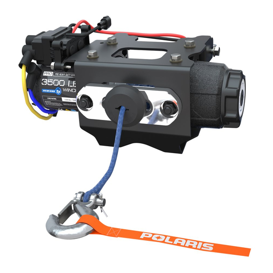
1
Winch - 3500 HDDS
8
1
Hook, Winch Latch
®
POLARIS
®
PRO HD WINCH
Instr 9927475
Rev 01 2017-02
Page 1 of 14
PART NUMBER
2205636
2413444
2879316
-
-
1022577
2206383
2411836
Advertisement
Table of Contents

Related Manuals for Polaris SPORTSMAN PRO HD 2882242


Summary of Contents for Polaris SPORTSMAN PRO HD 2882242
- Page 1 PRO HD WINCH P/N 2882242 APPLICATION Verify accessory fitment at Polaris.com. BEFORE YOU BEGIN Read these instructions and check to be sure all parts and tools are accounted for. Please retain these installation instructions for future reference and parts ordering information.
-
Page 2: Tools Required
® IMPORTANT Your SPORTSMAN ® POLARIS ® PRO HD WINCH KIT is exclusively designed for your vehicle. Please read the installation instructions thoroughly before beginning. Installation is easier if the vehicle is clean and free of debris. For your safety, and to ensure a satisfactory installation, perform all installation steps correctly in the sequence shown. -
Page 3: Installation Instructions
INSTALLATION INSTRUCTIONS 3. Open the front rack and remove rubber seal NOTE This kit contains the same components as Sportsman (XP) winch kit (PN 2882241), but have been pre-assembled differently. If you need to install this kit on a Sportsman (XP) vehicle, refer to image below that shows the contactor location and wire routing for Sportsman (XP) winch kit, and reassemble the contactor and wiring to match below... - Page 4 5. Lift the front cover upwards slowly to disengage 9. Remove lower front bumper cover from vehicle the tabs on front cover from the slots as shown. by removing four bolts as shown. Retain bolts for use during reinstallation. 6. Disconnect black (negative) and red (positive) cables from battery.
-
Page 5: Winch Installation
2. Locate white contactor connection on winch NOTE assembly. If it is secured to the winch assembly Before installing the winch kit add or replace the with a plastic tie, cut the tie to allow the wires to be proper fluid to your front gearcase as required per routed properly. -
Page 6: Control Box Installation
4. Route red (positive) and black (negative) 2. Route power wires to battery area and connect red winch cables on the side of the radiator then or orange wire from control box to orange wire on behind it to reach the three terminal bus bar as the vehicle’s main wire harness as seen below. - Page 7 2. Connect white electrical connectors as seen in the 4. Secure all remaining wires to vehicle main wire top photo of the Electrical Connections Reference harness using cable ties as shown. Guide. Route power wires to battery area and connect red or orange wire on control box to orange wire on vehicle main wire harness as seen below.
-
Page 8: Final Inspection
WIRELESS REMOTE HOLDER INSTALLATION REINSTALLATION 1. Wireless remote holder can be installed in desired 1. Reinstall the lower front bumper cover . If you location on vehicle. Use the screws provided in the plan to use a plow, do not reinstall winch cover wireless remote kit for holder installation. -
Page 9: Wireless Remote Operation
HANDLEBAR SWITCH OPERATION WIRELESS REMOTE OPERATION • When properly installed, the handlebar switch • When properly installed, the wireless remote will allows you to operate the winch while seated on the allow you to operate the winch from off the vehicle, vehicle. -
Page 10: Autostop Operation
AUTOSTOP OPERATION The high gear setting is meant for rapid recovery mode only and should not be used while the rope is The Autostop system is meant to help prevent under load. To shift into high gear, rotate the gear damage to the winch system from over-tightening of shifting knob clockwise until the “H”... -
Page 11: Troubleshooting
RAPID RECOVERY WINCH FUNCTION How to shift To operate the Rapid Recovery, make sure the winch Your winch is equipped to quickly reel in the winch is not in operation and the rope is not in tension. rope when being used under no-load conditions. Rotate the shift knob fully clockwise to engage “High”... - Page 12 SYMPTOM POSSIBLE CAUSES RECOMMENDED SOLUTION touching fairlead, check color of wires at connectors to make sure they match on both sides of the connection (in case two wires have been switched in the connector). Winch makes noise but rope does Contactor powered, but not winch If you can hear a clicking sound not move...
- Page 13 ELECTRICAL CONNECTION REFERENCE GUIDE Winch with auto fairlead, wireless remote, and handle bar switch Winch with auto fairlead and handle bar switch Winch with roller fairlead and handle bar switch Instr 9927475 Rev 01 2017-02 Page 13 of 14...
-
Page 14: Feedback Form
9927475 FEEDBACK FORM A feedback form has been created for the installer to provide any comments, questions FEEDBACK FORM or concerns about the installation instructions. The form is viewable on mobile devices by scanning the QR code or by clicking HERE if viewing on a PC.
Need help?
Do you have a question about the SPORTSMAN PRO HD 2882242 and is the answer not in the manual?
Questions and answers