Johnson Controls S300 Series Hardware Installation
Hide thumbs
Also See for S300 Series:
- Hardware installation manual (47 pages) ,
- Hardware installation (44 pages) ,
- Hardware installation manual (29 pages)

Related Manuals for Johnson Controls S300 Series


Summary of Contents for Johnson Controls S300 Series
- Page 1 S300 Series hardware installation S300-DIN-RDR8S and S300-DIN-I32O16 24-10489-19 Revision B December 2017...
- Page 2 If this document is translated from the original English version by Johnson Controls, all reasonable endeavors will be used to ensure the accuracy of translation. Johnson Controls shall not be liable for any translation errors contained herein or for incidental or consequential damages in connection with the furnishing or use of this translated material.
- Page 3 Declaration of Conformity United States: This equipment has been tested and found to comply with the limits for a Class B digital device, pursuant to Part 15 of the FCC rules. These limits are designed to provide reasonable protection against harmful interference in a residential installation. This equipment generates, uses and can radiate radio frequency energy and, if not installed and used in accordance with the instructions, may cause harmful interference to radio communications.
- Page 4 UNDERWRITERS LABORATORIES COMPLIANCE VERIFICATION SHEET The following model numbers are listed under Underwriters Laboratories Inc. ® (UL) 1076 for Proprietary Burglar Alarm Units and Systems, UL 294 for Access Control Systems Units and Underwriters Laboratories of Canada ULC/ORD-C1076-86. S300-DIN-RDR8S S300-DIN-I32O16 When installed at the site the following requirements must be met to comply with these standards.
-
Page 5: Installation
RDR8S and I32O16 Hardware Installation Introduction 24-10489-19 Rev. B ARDWARE NSTALLATION This document provides hardware installation instructions for the S300-DIN- RDR8S and the S300-DIN-I32O16. NTRODUCTION The S300-DIN-RDR8S and S300-DIN-I32O16 modules provide interface control for access and security devices associated with up to eight doors. : Throughout this manual the S300-DIN-RDR8S module is also referred to as the RDR8S, while the S300-DIN-I32O16 module is referred to as the I32O16. -
Page 6: Key Features
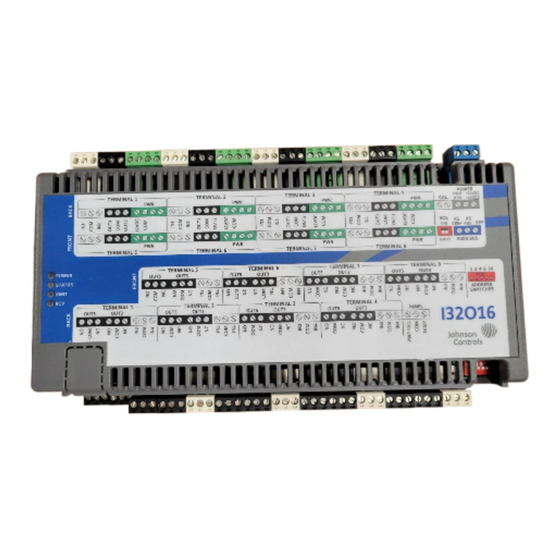
RDR8S and I32O16 Hardware Installation Key Features 24-10489-19 Rev. B Figure 2: S300-DIN-I32O16 EATURES The key features of the RDR8S include: • Wide range nominal voltage for power source (+12 to 24VDC) • Support for S300 bus communications at 9600 or 19200 (Auto baud rate detection 9600/19200 baud) •... - Page 7 RDR8S and I32O16 Hardware Installation Key Features 24-10489-19 Rev. B • The OSDP Reader feature supports the use of HID OSDP Keypad Readers type and HID OSDP Reader type (no keypad). The OSDP Reader feature: – Adds Open Supervised Device Protocol (OSDP) v1.1 reader device support.
- Page 8 RDR8S and I32O16 Hardware Installation Application 24-10489-19 Rev. B The following inputs are shared by all interfaces (one per unit): • Calibration resistor input • Supervised panel tamper and power fail inputs PPLICATION The RDR8S module supports up to eight doors per unit. The I32O16 module supports 32 inputs, 16 relay outputs, and 16 open collector outputs per unit.
- Page 9 Check the purchase order against the packing slips to ensure the order is complete. If the contents of a container are damaged in any way, notify the carrier and your Johnson Controls representative immediately. Report any discrepancies to your Johnson Controls representative. Save the packing materials for possible return shipments.
- Page 10 RDR8S and I32O16 Hardware Installation Mounting 24-10489-19 Rev. B To remove a module from the DIN rail: 1. Pull down the clips at the bottom of the module. 2. Pull the bottom of the module out and lift it up. Flat Surface Mounting To mount an RDR8S or I32O16 module on a flat surface: 1.
- Page 11 RDR8S and I32O16 Hardware Installation Description of Signals 24-10489-19 Rev. B ESCRIPTION OF IGNALS All interface signals are connected via plug-in connectors. For a description of the I/O interface signals, see: • “Input Point Signals” on page 24 • “Output Point Signals” on page 26...
- Page 12 RDR8S and I32O16 Hardware Installation Description of Signals 24-10489-19 Rev. B The following figures show the details of the terminal blocks. RDR8S DOOR INTERFACE: I32O16 TERMINAL INTERFACE: ONE OF 8 READERS ONE OF 8 TERMINALS READER TERMINAL DOOR 1 LEDS PWR/COMM READER TERMINAL...
- Page 13 RDR8S and I32O16 Hardware Installation Description of Signals 24-10489-19 Rev. B Calibration Resistor CAL. Figure 3: RDR8S and I32O16 Interface: Calibration Resistor To the power supply POWER +12VDC +24VDC Figure 4: RDR8S and I32O16 Interface: Power Supply RDR8S Input/Output Points Device Interface Lines DATA0/RS485- and DATA1/RS485- –...
- Page 14 RDR8S and I32O16 Hardware Installation Description of Signals 24-10489-19 Rev. B Input Points Description of Signals – The following are internally pulled up inputs: – Reader 1: Door Sensor, REX, Tamper, Spare – Reader 2: Door Sensor, REX, Tamper, Spare –...
- Page 15 RDR8S and I32O16 Hardware Installation Description of Signals 24-10489-19 Rev. B Reference – These signals are referenced to logic ground (COM). Protection – Each signal has a 30V transient voltage suppressor between it and system ground. Relay Output Points Description of Signals – NC, NO, and COM are the three connections to a single pole, double throw relay.
- Page 16 RDR8S and I32O16 Hardware Installation Description of Signals 24-10489-19 Rev. B – Terminal 7: IN1, IN2, IN3, IN4 – Terminal 8: IN1, IN2, IN3, IN4 – Panel Power Fail – Panel Tamper The allowable voltage range for these signals is 0-12VDC. Reference –...
- Page 17 RDR8S and I32O16 Hardware Installation Description of Signals 24-10489-19 Rev. B Relay Output Points Description of Signals – NC, NO, and COM are the three connections to a single pole, double throw relay. The following are the relay outputs: – Terminal 1: OUT5, OUT3 –...
-
Page 18: Cable Requirements
RDR8S and I32O16 Hardware Installation Description of Signals 24-10489-19 Rev. B Cable Requirements Maximum Segment Description Recommended Cable Type Length RDR8S or I32O16 to Listed, 18 AWG, hook-up wire Wire should fit within the Power Supply enclosure. RDR8S or I32O16 to Listed, 18 AWG, 1 twisted pair 4000 feet (1219 m) Controller... - Page 19 RDR8S and I32O16 Hardware Installation Description of Signals 24-10489-19 Rev. B Maximum Segment Description Recommended Cable Type Length General Purpose Belden 8442, 1 twisted, 500 feet (152 m) Input unshielded pair, 22 AWG to each detector General Purpose Belden 9740, 1 twisted, Depends on load.
- Page 20 RDR8S and I32O16 Hardware Installation Description of Signals 24-10489-19 Rev. B Power Supply For power wiring with the enclosure, use the cable assembly shown in the following figure. For more information refer to the manual provided with the enclosure. Connector (3-pole, gray) for RDR8S or I32O16 module (PWR return) +24VDC...
- Page 21 Figure 7: “Daisy Chain” Connector Details Connecting the COM (Ground) Wire When daisy-chain connecting an RDR8S or I32O16, wire the devices according to the following illustration: RDR8S or I32O16 S300 Series S300 Series Connector (RS-485) Connector (RS-485) Connector (RS-485) RS485-...
- Page 22 RDR8S and I32O16 Hardware Installation Description of Signals 24-10489-19 Rev. B The following RDR8S reader terminal output points can be re-assigned: – Red LED – Green LED – Reader Strike – Reader Shunt The following RDR8S reader terminal input points can be re-assigned: –...
- Page 23 RDR8S and I32O16 Hardware Installation Description of Signals 24-10489-19 Rev. B Wiring Input Devices Tamper Switch Wiring The tamper switch connects to a general purpose input point. To be operational, the tamper switch must be wired to one of the unused input points on any RDR8S in the enclosure, and programmed in the controller.
- Page 24 RDR8S and I32O16 Hardware Installation Description of Signals 24-10489-19 Rev. B 4-State Inputs Wiring: N/O Switch e.g. DOOR Note: The 4-state wiring SENSOR requires two resistors of the same value. The resistors can be 150-2000 Ohms, 1%, 1/4W. The recommended resistor is 1200 Ohms.
-
Page 25: Setup And Adjustments
(alarm, secure, open, or short) to be calibrated. Ground Every metal DIN enclosure in a Johnson Controls installation must have its chassis bonded to a verified electrical ground (earth). CAUTION: Conduit ground, cold water pipes, unbrazed joints or dissimilar metals are unacceptable in the path of either building or supplemental ground. - Page 26 RDR8S and I32O16 Hardware Installation Setup and Adjustments 24-10489-19 Rev. B S300/RS-485 Isolation and Protection Isolation and protection is provided by the following components: – Three optical isolators (optocouplers) – Two self-resetting switch thermistors – Two transient voltage suppressors (TVSs) Address Switches The following figure shows the location of the adjustable 5-position address switch.
- Page 27 RDR8S and I32O16 Hardware Installation Setup and Adjustments 24-10489-19 Rev. B Table 1: S300 Bus Address DIP Switch Number Hardware Module Label on the Module Number (S300 Bus Address) End-of-Line (EOL) Switch The EOL switch is used to provide EOL termination for the S300 bus. On the RDR8S and I32O16 modules the EOL switch is a single throw 3-pole DIP switch.
- Page 28 RDR8S and I32O16 Hardware Installation Setup and Adjustments 24-10489-19 Rev. B The following figure shows the location of the EOL switch. EOL switch The EOL switch is OFF (down) by factory default. Network devices at either end of the S300 network must be set as network terminated devices.
- Page 29 RDR8S and I32O16 Hardware Installation Setup and Adjustments 24-10489-19 Rev. B Table 2: RDR8S and I32O16 Input Points RDR8S I32O16 “Reader n Door Sensor” “Terminal n IN1” DOOR n Input Input Can be calibrated to 2- Can be calibrated to 2-state or state or 4-state.
- Page 30 RDR8S and I32O16 Hardware Installation Setup and Adjustments 24-10489-19 Rev. B Table 2: RDR8S and I32O16 Input Points RDR8S I32O16 “Power Fail” “Power Fail” PANEL PANEL General Purpose Input General Purpose Input Can be calibrated to 2- Can be calibrated to 2-state or state or 4-state.
-
Page 31: Technical Specifications
RDR8S and I32O16 Hardware Installation Technical Specifications 24-10489-19 Rev. B Table 3: RDR8S and I32O16 Output Points RDR8S I32O16 “Reader n Shunt” “Terminal n OUT3” SHUNT OUT3 Output is a relay. It can be timed, set, reset, fast flash, or slow flash. Output is a relay. -
Page 32: Routine Maintenance
RDR8S and I32O16 Hardware Installation Maintenance 24-10489-19 Rev. B Item Specification Certifications FCC, Class B CE Mark C-Tick ICES-003, Class B Mounting DIN rail Specifications Flat surface Dimensions 5.15 H x 10.58 W x 2.5 D inches (13.07 cm x 26.88 cm x 6.36 Weight 2.75 lb (1.2 kg) Ambient... - Page 33 RDR8S and I32O16 Hardware Installation Maintenance 24-10489-19 Rev. B Impaired Performance Conditions Condition Information Location Unit environment not as specified See “Technical Specifications” on page 27. Unit power and grounding not as See “Power Supply” on page 16 and “Ground” specified on page 21.
- Page 34 RDR8S and I32O16 Hardware Installation Maintenance 24-10489-19 Rev. B Fuses The RDR8S and I32O16 have no replaceable fuses.
- Page 35 Security Solutions (805) 522-5555 www.johnsoncontrols.com We welcome your comments at BE-techpubs-security@jci.com.
Need help?
Do you have a question about the S300 Series and is the answer not in the manual?
Questions and answers