Johnson Controls S300 Series Hardware Installation
Hide thumbs
Also See for S300 Series:
- Hardware installation manual (47 pages) ,
- Hardware installation (35 pages) ,
- Hardware installation manual (21 pages)

Related Manuals for Johnson Controls S300 Series


Summary of Contents for Johnson Controls S300 Series
- Page 1 S300 Series hardware installation S300-DIN-RDR2SA and S300-DIN-I8O4 24-10239-596 Revision D December 2017...
- Page 2 If this document is translated from the original English version by Johnson Controls, all reasonable endeavors will be used to ensure the accuracy of translation. Johnson Controls shall not be liable for any translation errors contained herein or for incidental or consequential damages in connection with the furnishing or use of this translated material.
- Page 3 Declaration of Conformity United States: This equipment, S300-DIN-RDR2SA and S300-DIN-I8O4, has been tested and found to comply with the limits for a Class B digital device, pursuant to Part 15 of the FCC rules. These limits are designed to provide reasonable protection against harmful interference in a residential installation.
- Page 4 UNDERWRITERS LABORATORIES COMPLIANCE VERIFICATION SHEET The following model numbers are listed under Underwriters Laboratories Inc. ® (UL) 1076 for Proprietary Burglar Alarm Units and Systems, UL 294 for Access Control Systems Units and Underwriters Laboratories of Canada ULC/ORD-C1076-86. S300-DIN-RDR2SA S300-DIN-I8O4 When installed at the site the following requirements must be met to comply with these standards.
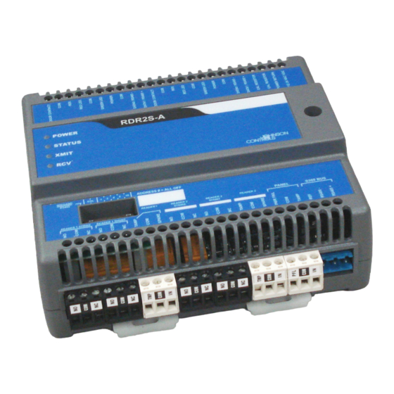
- Page 5 RDR2S-A and I8O4 Hardware Installation Introduction 24-10239-596 Rev. D ARDWARE NSTALLATION This document provides hardware installation instructions for the S300-DIN-RDR2SA and the S300-DIN-I8O4. NTRODUCTION The S300-DIN-RDR2SA and S300-DIN-I8O4 modules provide interface control for access and security devices associated with up to two doors. : Throughout this manual the S300-DIN-RDR2SA module is also referred to as the RDR2S-A, while the S300-DIN-I8O4 module is referred to as the I8O4.
- Page 6 RDR2S-A and I8O4 Hardware Installation Introduction 24-10239-596 Rev. D The key features of the RDR2S-A include: • Wide range nominal voltage for power source (+12 to 24VDC, 16 to 24VAC) • Support for S300 RS-485 bus communications at 9600 or 19200 baud (Automatic baud rate detection) •...
- Page 7 RDR2S-A and I8O4 Hardware Installation Introduction 24-10239-596 Rev. D The OSDP reader support includes communicating reader status. CK721-A Controller RDR8S RDR2S-A (PS-218) (PS-217) OSDP V1 reader OSDP V1 reader OSDP V1 Wiegand Wiegand reader reader reader Note: The RDR2S-A can support up to two OSDP readers or two Wiegand readers.
- Page 8 RDR2S-A and I8O4 Hardware Installation Introduction 24-10239-596 Rev. D S300-DIN-I804 Module Figure 3: S300-DIN-I8O4 The key features of the I8O4 include: • Wide range nominal voltage for power source (+12 to 24VDC, 16 to 24VAC) • Support for S300/RS-485 bus communications at 9600 or 19200 baud (Automatic baud rate detection) •...
-
Page 9: Installation
If the contents of a container are damaged in any way, notify the carrier and your Johnson Controls representative immediately. Report any discrepancies to your Johnson Controls representative. Save the packing materials for possible return shipments. - Page 10 OUNTING The RDR2S-A or I8O4 module can be mounted on a flat surface, DIN rail, or in a Johnson Controls’ approved enclosure (for example: S300-DIN). For information on mounting the RDR2S-A or I8O4 module in an enclosure, refer to the manual provided with the enclosure.
- Page 11 RDR2S-A and I8O4 Hardware Installation Mounting 24-10239-596 Rev. D Flat Surface Mounting To mount an RDR2S-A or I8O4 module on a flat surface: 1. Make sure no connectors obstruct access to the clips on the bottom of the module. If necessary, remove the connectors. 2.
- Page 12 RDR2S-A and I8O4 Hardware Installation Description of Signals 24-10239-596 Rev. D ESCRIPTION OF IGNALS All interface signals are connected via plug-in connectors. For a description of the I/O interface signals, see: • Input Point Signals on page 33 • Output Point Signals on page 35 The figures below are outlines of the position of terminal blocks, followed by detailed drawings.
- Page 13 RDR2S-A and I8O4 Hardware Installation Description of Signals 24-10239-596 Rev. D TERMINAL 1 TERMINAL 2 TERMINAL 1 TERMINAL 2 POWER I8O4 PANEL S300 BUS TERMINAL 1 TERMINAL 2 Figure 5: I8O4 Terminal Blocks Outline...
- Page 14 RDR2S-A and I8O4 Hardware Installation Description of Signals 24-10239-596 Rev. D I8O4 TERMINAL INTERFACE: RDR2S-A DOOR INTERFACE: ONE OF TWO TERMINALS ONE OF TWO READERS READER TERMINAL READER TERMINAL READER READER READER OUT5 OUT3 STRIKE SHUNT TAMPER Figure 6: RDR2S-A Door Interface and I8O4 Terminal Interface...
-
Page 15: Calibration Resistor
RDR2S-A and I8O4 Hardware Installation Description of Signals 24-10239-596 Rev. D Calibration Resistor CAL. Figure 7: RDR2S-A and I8O4 Interface: Calibration Resistor To the power supply POWER Figure 8: RDR2S-A and I8O4 Interface: Power Supply... - Page 16 RDR2S-A and I8O4 Hardware Installation Description of Signals 24-10239-596 Rev. D...
- Page 17 RDR2S-A and I8O4 Hardware Installation Description of Signals 24-10239-596 Rev. D...
- Page 18 RDR2S-A and I8O4 Hardware Installation Description of Signals 24-10239-596 Rev. D RDR2S-A Input Points Wiegand Input Description of Signals – DATA0/RS485- and DATA1/RS485+ from each reader, complying with the Wiegand interface specification. These signals are pulled up to 5VDC by internal 3.92 K Ohm resistors when the Wiegand/RS485 switch is on.
- Page 19 RDR2S-A and I8O4 Hardware Installation Description of Signals 24-10239-596 Rev. D Open Collector Output Points Description of Signals – The following are open collector outputs: • Reader 1 Red LED • Reader 1 Green LED • Reader 2 Red LED •...
- Page 20 RDR2S-A and I8O4 Hardware Installation Description of Signals 24-10239-596 Rev. D I8O4 Input/Output Points Input Points Description of Signals – The following are internally pulled up inputs: • Terminal 1: IN1, IN2, IN3, IN4 • Terminal 2: IN1, IN2, IN3, IN4 •...
-
Page 21: Cable Requirements
RDR2S-A and I8O4 Hardware Installation Cable Requirements 24-10239-596 Rev. D Relay Output Points Description of Signals – NC, NO, and COM are the three connections to a single pole, double throw relay. The following are the relay outputs: • Terminal 1: OUT5, OUT3 •... -
Page 22: Cable Routing
RDR2S-A and I8O4 Hardware Installation Cable Requirements 24-10239-596 Rev. D Table 2: Cable Requirements Description Recommended Cable Type Maximum Segment Length Request to Exit Belden 8442, 1 twisted, 500 feet (152 m). unshielded pair, 22 AWG Reader Power Belden 9740, 1 twisted, Refer to reader unshielded pair, 18 AWG manufacturer’s specification... - Page 23 RDR2S-A and I8O4 Hardware Installation Cable Requirements 24-10239-596 Rev. D All cables must conform with the following regulations: • National Electrical Code • NFPA 70 • Local electrical codes • Canadian Electric Code C22.1 (installations in Canada) • BSI Standard BS7671, latest edition (installations in Great Britain) Cabling should be made using good wiring practices and should be long enough to allow service loops at their terminations in the enclosure.
- Page 24 RDR2S-A and I8O4 Hardware Installation Cable Requirements 24-10239-596 Rev. D When connecting multiple RDR2S-A or I8O4 modules, wire the modules in parallel following the “daisy chain” pattern as shown in the following figures. To construct the power wiring, use listed 18 AWG wires. to the next DC power cable RDR2S-A...
- Page 25 Cable Requirements 24-10239-596 Rev. D Connecting the COM (Ground) Wire When daisy-chain connecting an RDR2S-A, wire the devices according to the following illustration: RDR2S-A or I8O4 S300 Series S300 Series Connector (RS-485) Connector (RS-485) Connector (RS-485) 1 2 3 4 5...
- Page 26 RDR2S-A and I8O4 Hardware Installation Cable Requirements 24-10239-596 Rev. D 4-State Inputs Wiring: N/C Switch e.g. DOOR Note: The 4-state wiring CONTACT requires two resistors of the same value. The resistors can be 150-2000 Ohms, 1%, 1/4W. The recommended resistor is 1200 Ohms. 4-State Inputs Wiring: N/O Switch e.g.
-
Page 27: Setup And Adjustments
This method allows an input in any state (alarm, secure, open, or short) to be calibrated. Ground Every metal DIN enclosure in a Johnson Controls installation must have its chassis bonded to a verified electrical ground (earth). : Conduit ground, cold water pipes, unbrazed joints or dissimilar MPORTANT metals are unacceptable in the path of either building or supplemental ground. - Page 28 RDR2S-A and I8O4 Hardware Installation Setup and Adjustments 24-10239-596 Rev. D S300/RS485 Connection The following figure shows a portion of the top cover of the RDR2S-A or I8O4 module with adjustable Wiegand/RS485, EOL, and address switches. Address switches Wiegand EOL Switches: switch SW2 position #2 and SW2 position #3...
- Page 29 RDR2S-A and I8O4 Hardware Installation Setup and Adjustments 24-10239-596 Rev. D The RDR2S-A and I8O4 modules follow the same rules as other terminated devices. See the following figure to determine the appropriate EOL setting for each RDR2S-A and I8O4 module in your network. Baud Rates The RDR2S-A and I8O4 modules support autobaud operations on the S300 bus between 9600 and 38400 bps and do not require any switch...
- Page 30 RDR2S-A and I8O4 Hardware Installation Setup and Adjustments 24-10239-596 Rev. D Table 3: Legacy versus Physical Address Mode Legacy Address Mode Physical Address Mode Used with: Used with: CK705 CK721-A v. 3.0+ CK720 CK722 CK721 Note: Physical address mode is recommended for new installations with CK721-A v.
- Page 31 RDR2S-A and I8O4 Hardware Installation Setup and Adjustments 24-10239-596 Rev. D Address Mode Switches (SW1) The address mode is determined by the position of the address mode switches (SW1). They are located under the module cover. Switch positions 1 through 4 determine address mode, switch positions 5 through 8 are not used.
- Page 32 RDR2S-A and I8O4 Hardware Installation Setup and Adjustments 24-10239-596 Rev. D Legacy and Physical Address Mode Compatibility The following table describes address mode compatibility of modules with different firmware versions. Table 4: Address Mode Compatibility Module and Allowed address Comments / Other devices firmware version mode...
- Page 33 RDR2S-A and I8O4 Hardware Installation Setup and Adjustments 24-10239-596 Rev. D Address Switches (SW2) The RDR2S-A and I8O4 modules have 5 address switches (see page 31). Controller Module Address CK722 Switch positions 4 to 8 CK721-A version 3.0 (physical address mode) Switch positions 4 to 8 CK721-A version 3.0 (legacy address mode) Switch positions 4 to 6...
- Page 34 RDR2S-A and I8O4 Hardware Installation Setup and Adjustments 24-10239-596 Rev. D Table 5: Terminal Addressing for CK721-A (V3.0, Physical Address Mode) and CK722 Controllers DIP Switch Number Label on the Module Hardware Wiegand Module # RS485 page 14 page 24...
- Page 35 RDR2S-A and I8O4 Hardware Installation Setup and Adjustments 24-10239-596 Rev. D Table 6: Terminal Addressing for CK721-A (Versions Prior to 3.0), CK721-A (Version 3.0, Legacy Mode), CK721, and CK720/CK705 Controllers DIP Switch Number Label on the Module Terminal Wiegand Number RS485 1 &...
- Page 36 RDR2S-A and I8O4 Hardware Installation Setup and Adjustments 24-10239-596 Rev. D An RDR2S-A module sharing the same address with a legacy I/O device (S300-I16, S300-IO8, S300-SIO8 or S300-SI8) must have switch position SW1-3 or SW1-4 disabled. The following RDR2S-A reader terminal output points can be re- assigned: •...
- Page 37 RDR2S-A and I8O4 Hardware Installation Setup and Adjustments 24-10239-596 Rev. D : On CK721-A controllers, a write to flash must be performed after completion of input point/output point disassociation configuration. Input Point Signals Table 7: RDR2S-A and I8O4 Input Points Application-Specific Use General Purpose Use (RDR2S-A with...
- Page 38 RDR2S-A and I8O4 Hardware Installation Setup and Adjustments 24-10239-596 Rev. D Table 7: RDR2S-A and I8O4 Input Points Application-Specific Use General Purpose Use (RDR2S-A with (RDR2S-A only) I/O disassociation or I8O4) “Reader n Tamper” “Terminal n IN4” READER n TERMINAL n Input Terminal n Input General Purpose Input Point 4...
- Page 39 RDR2S-A and I8O4 Hardware Installation Setup and Adjustments 24-10239-596 Rev. D Output Point Signals Table 8: RDR2S-A and I8O4 Output Points Application-Specific Use (RDR2S-A General Purpose Use (RDR2S-A with I/O only) disassociation or I8O4) “Reader n Red LED” “Terminal n OUT1” Application Specific Output General Purpose Output Output is set every time...
-
Page 40: Specifications
RDR2S-A and I8O4 Hardware Installation Technical Specifications 24-10239-596 Rev. D ECHNICAL PECIFICATIONS The terminal is expected to operate at moderate temperature variation, non- condensing humidity variation, moderate vibration, and possible dust contamination. Item Specification Input Power +12 to +24VDC or 16 to 24VAC at 24W Reader Interface 2-wire Wiegand (up to 256 bits) -
Page 41: Maintenance
RDR2S-A and I8O4 Hardware Installation Maintenance 24-10239-596 Rev. D AINTENANCE This section provides maintenance instructions, operational testing procedures, and information on replacement parts. LEDs The RDR2S-A and I8O4 modules have 4 LEDs: • Power (Power): On during normal operation. • Status (STATUS): Blinks every second when unit is operational. - Page 42 RDR2S-A and I8O4 Hardware Installation Maintenance 24-10239-596 Rev. D 4. Present a valid card to each reader connected to the RDR2S-A reader interface and then verify that access is granted (green lamp lights). 5. Present an invalid card to each reader connected to the RDR2S-A reader interface and then verify that access is denied (red lamp lights).
- Page 43 RDR2S-A and I8O4 Hardware Installation RDR2S-A Address Mode and Performance 24-10239-596 Rev. D RDR2S-A A DDRESS ODE AND ERFORMANCE The following graph presents RDR2S-A performance data in physical versus legacy address mode. The data was derived by connecting a specified number of modules on the RS-485 bus and measuring the response time between reading two badges by two readers on the same module and unlocking two doors.
- Page 44 Security Solutions (805) 522-5555 www.johnsoncontrols.com We welcome your comments at BE-techpubs-security@jci.com.
Need help?
Do you have a question about the S300 Series and is the answer not in the manual?
Questions and answers