Johnson Controls S300 Series Hardware Installation Manual
Hide thumbs
Also See for S300 Series:
- Hardware installation manual (47 pages) ,
- Hardware installation (44 pages) ,
- Hardware installation manual (31 pages)

Related Manuals for Johnson Controls S300 Series


Summary of Contents for Johnson Controls S300 Series
- Page 1 S300 Series S300-DIN-RDR8S and S300-DIN-I32O16 Hardware Installation Manual July, 2010 24-10489-0 Revision B...
- Page 2 Controls, Inc. are not intended to duplicate nor replace other manufacturer’s documentation. If this document is translated from the original English version by Johnson Controls, Inc., all reasonable endeavors will be used to ensure the accuracy of translation. Johnson Controls, Inc.
-
Page 3: Canadian Notice
Due to continuous development of our products, the information in this document is subject to change without notice. Johnson Controls, Inc. shall not be liable for errors contained herein or for incidental or consequential damages in connection with furnishing or use of this material. Contents of this publication may be preliminary and/or may be changed at any time without any obligation to notify anyone of such revision or change, and shall not be regarded as a warranty. - Page 4 UNDERWRITERS LABORATORIES COMPLIANCE VERIFICATION SHEET The following model numbers are listed under Underwriters Laboratories UL 1076 for Proprietary Burglar Alarm Units and Systems and UL 294 for Access Control Systems Units. S300-DIN-RDR8S S300-DIN-I32O16 When installed at the site the following requirements must be met to comply with these standards. 1.
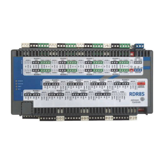
- Page 5 Throughout this manual the S300-DIN-RDR8S module is also referred to as the RDR8S, while the S300-DIN-I32O16 module is referred to as the I32O16. Figure 1: S300-DIN-RDR8S 24-10489-0 Rev. B This document contains confidential and proprietary information of Johnson Controls, Inc. © 2010 Johnson Controls, Inc.
-
Page 6: Key Features
The following inputs are shared by all interfaces (one per unit): - Calibration resistor input - Supervised panel tamper and power fail inputs 24-10489-0 Rev. B This document contains confidential and proprietary information of Johnson Controls, Inc. © 2010 Johnson Controls, Inc. -
Page 7: Installation
If the contents of a container are damaged in any way, notify the carrier and your Johnson Controls representative immediately. Report any discrepancies to your Johnson Controls representative. Save the packing materials for possible return shipments. 24-10489-0 Rev. B This document contains confidential and proprietary information of Johnson Controls, Inc. -
Page 8: Package Contents
2. Fully extend the bottom clips. 3. Mount the module to the surface with mounting screws. 4. Replace the connectors, if previously removed. 24-10489-0 Rev. B This document contains confidential and proprietary information of Johnson Controls, Inc. © 2010 Johnson Controls, Inc. -
Page 9: Power Source
“Input Point Signals” on page 19 “Output Point Signals” on page 21 The following figures show the details of the terminal blocks. 24-10489-0 Rev. B This document contains confidential and proprietary information of Johnson Controls, Inc. © 2010 Johnson Controls, Inc. - Page 10 TERMINAL DOOR 1 LEDS PWR/COMM READER TERMINAL STRIKE SHUNT INPUTS OUT5 OUT3 Figure 3: RDR8S Door Interface and I32O16 Terminal Interface 24-10489-0 Rev. B This document contains confidential and proprietary information of Johnson Controls, Inc. © 2010 Johnson Controls, Inc.
-
Page 11: Input Points
Reader 7: Door Sensor, REX, Tamper, Spare Reader 8: Door Sensor, REX, Tamper, Spare Panel Power Fail Panel Tamper 24-10489-0 Rev. B This document contains confidential and proprietary information of Johnson Controls, Inc. © 2010 Johnson Controls, Inc. - Page 12 Reader 3: Strike, Shunt Reader 4: Strike, Shunt Reader 5: Strike, Shunt Reader 6: Strike, Shunt 24-10489-0 Rev. B This document contains confidential and proprietary information of Johnson Controls, Inc. © 2010 Johnson Controls, Inc.
- Page 13 COM is required for 2-state operation. For wiring details see “Wiring Input Devices” on page 15. 24-10489-0 Rev. B This document contains confidential and proprietary information of Johnson Controls, Inc. © 2010 Johnson Controls, Inc.
- Page 14 Terminal 8: OUT5, OUT3 – The relay is a dry contact relay rated at 1A at 24VDC, 25VA maximum. Reference 24-10489-0 Rev. B This document contains confidential and proprietary information of Johnson Controls, Inc. © 2010 Johnson Controls, Inc.
-
Page 15: Cable Requirements
24-10489-0 Rev. B This document contains confidential and proprietary information of Johnson Controls, Inc. © 2010 Johnson Controls, Inc. -
Page 16: Cable Routing
Figure 6: Cable Assembly for Power Wiring Do not connect the power cable to the RDR8S or I32O16 until all wiring is complete. CAUTION 24-10489-0 Rev. B This document contains confidential and proprietary information of Johnson Controls, Inc. © 2010 Johnson Controls, Inc. - Page 17 1 2 3 4 5 1 2 3 4 5 Figure 9: Connecting an RDR8S or I32O16 in the “Daisy-Chain” Wiring Pattern 24-10489-0 Rev. B This document contains confidential and proprietary information of Johnson Controls, Inc. © 2010 Johnson Controls, Inc.
- Page 18 Reader REX Input 2 On CK721-A controllers, a write to flash must be performed after completion of input point/output point disassociation configuration. 24-10489-0 Rev. B This document contains confidential and proprietary information of Johnson Controls, Inc. © 2010 Johnson Controls, Inc.
- Page 19 Note: The 4-state wiring requires two SENSOR resistors of the same value. The resistors can be 150-2000 Ohms, 1%, 1/4W. The recommended resistor is 1200 Ohms. 24-10489-0 Rev. B This document contains confidential and proprietary information of Johnson Controls, Inc. © 2010 Johnson Controls, Inc.
- Page 20 This method allows an input in any state (alarm, secure, open, or short) to be calibrated. Ground Every metal DIN enclosure in a Johnson Controls installation must have its chassis bonded to a verified electrical ground (earth). Conduit ground, cold water pipes, unbrazed joints or dissimilar metals are unacceptable in the path of either building or supplemental ground.
-
Page 21: Address Switches
12/24 VDC supply power to the RDR8S/I32O16 and wait for the power LED to go off. Changes will not take effect until after the power is restored. 24-10489-0 Rev. B This document contains confidential and proprietary information of Johnson Controls, Inc. © 2010 Johnson Controls, Inc. - Page 22 RDR8S and I32O16 Modules Table 1: S300 Bus Address DIP Switch Number Label on the Module Hardware Module No. (S300 Bus Address) 24-10489-0 Rev. B This document contains confidential and proprietary information of Johnson Controls, Inc. © 2010 Johnson Controls, Inc.
- Page 23 In the following table, n denotes a reader/door number (RDR8S) or a terminal number (I32O16). n = 1, 2, 3, 4, 5, 6, 7, or 8 24-10489-0 Rev. B This document contains confidential and proprietary information of Johnson Controls, Inc. © 2010 Johnson Controls, Inc.
- Page 24 Note: For use only with 12VDC or 24VDC power supply. If used, “Power Fail” must be wired to a power fail monitoring circuit. 24-10489-0 Rev. B This document contains confidential and proprietary information of Johnson Controls, Inc. © 2010 Johnson Controls, Inc.
-
Page 25: Specifications
12VDC, 250mA (typical) Red indicator Green indicator General Purpose Inputs Resistive load Relay Outputs 1A max. 0-24 VDC / VAC, 25VA max 24-10489-0 Rev. B This document contains confidential and proprietary information of Johnson Controls, Inc. © 2010 Johnson Controls, Inc. -
Page 26: Routine Maintenance
Receive (RCV): Blinks when a character is received from the S300 bus. Routine Maintenance For the RDR8S or I32O16 maintenance, perform the operational testing monthly (see “Testing Procedure” on page 23). 24-10489-0 Rev. B This document contains confidential and proprietary information of Johnson Controls, Inc. © 2010 Johnson Controls, Inc. -
Page 27: Testing Procedure
Generic replacement terminal blocks can be ordered if lost. For more information on the parts listed, refer to the applicable catalog page. Fuses The RDR8S and I32O16 have no replaceable fuses. 24-10489-0 Rev. B This document contains confidential and proprietary information of Johnson Controls, Inc. © 2010 Johnson Controls, Inc. - Page 28 Hardware Installation RDR8S and I32O16 Modules 24-10489-0 Rev. B This document contains confidential and proprietary information of Johnson Controls, Inc. © 2010 Johnson Controls, Inc.
Need help?
Do you have a question about the S300 Series and is the answer not in the manual?
Questions and answers