Table of Contents
Advertisement
Quick Links
Application
The Metasys Network Automation Engine (NAE) is an
Ethernet-based, supervisory device that connects BAS
networks to IP networks. NAEs monitor and control
field-level building automation devices, including HVAC
equipment, lighting, security, and fire safety equipment.
At Release 11.0, the NAE55 is also FIPS 140-2 Level 1
compliant. FIPS 140-2 is a United States government
cybersecurity standard that approves cryptographic
modules/algorithms used for encryption. Use this
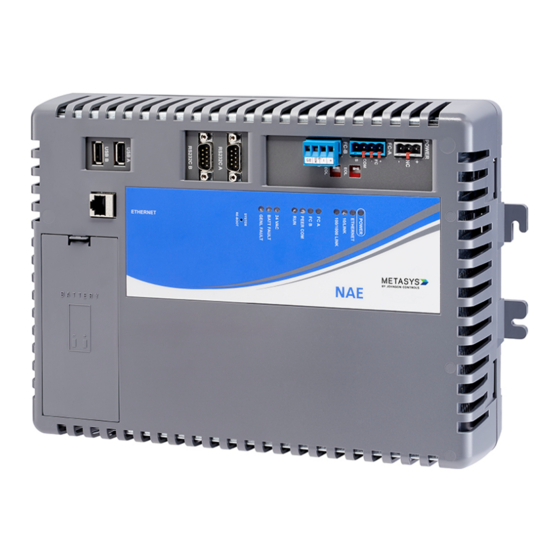
document to install the NAE. Figure 1 shows the NAE55
engine.
Figure 1: NAE55 Network Engine
The NAE offers various integration options. Ethernet
network integrations include the following options:
• Johnson Controls and 3rd party BACnet/IP, BACnet/SC
devices
• Simplex
Fire Alarm Control Unit (FACU)
®
• Cree
SmartCast
Lighting Control
®
®
• Molex
Lighting Control
®
• Tyco
C•CURE
9000 or victor
®
®
• Modbus TCP/IP
• KNX IP
• OPC UA integration at Metasys Release 11.0
Field Bus integrations include the following options:
• BACnet MS/TP
• N2 Bus
• LonWorks
(NAE552x models only)
®
• Modbus Remote Terminal Unit (RTU)
• Meter Bus (M-Bus)
• Zettler
Fire Panel
®
Video Management
®
NAE55 Installation Guide
Important: For any other custom integrations,
contact your local Systems Integration Services
(SIS) team before an upgrade. Updated drivers are
available on request.
In this installation guide, the term network engine
applies to any NAE55 model, unless otherwise stated.
For installation instructions on the NAE55s that are
approved for Metasys system smoke control applications,
refer to the NAE55 Installation Instructions (Part No.
24-10051-00132).
Note: At Metasys Release 10.0 and later, modems
(internal and external) and pagers are no longer
supported on NAE55 engines that run the Linux
operating system, but are still supported on
prior releases for engines that use a Windows
Embedded operating system. You can field-upgrade
a network engine at Release 9.0 that has an internal
modem to Release 10.0 or later to acquire new
release enhancements, but its modem and pager
functionality are lost. If you need modem and pager
functionality, do not upgrade the NAE55 engine to
Release 10.0 or later.
Installation
Follow these guidelines when installing the network
engine:
• Transport the network engine in the original container
to minimize vibration and shock damage to the network
engine.
• Verify that all the parts shipped with the network
engine. The data protection battery and network engine
ship together but are packaged separately.
• Do not drop the network engine or subject it to physical
shock.
• Do not open the network engine housing (except the
data protection battery compartment). The network
engine has no user-serviceable parts inside.
Parts included
• one MS-NAE55xx-x model
• one data protection battery
• one installation instructions sheet
Materials and special tools needed
You can mount the network engine by using the fasteners
option or the DIN rail option.
• Fasteners option - Three fasteners appropriate for the
mounting surface:
- #8 screws - North America
- M4 screws - Europe
• DIN rail option - 36 cm (14 in.) or longer section of 35
mm (1 1/8 in.) for DIN rail mount applications only.
MS-NAE5510-3, MS-NAE5510-3U, MS-NAE5520-3
Part No. 24-10051-43 Rev. W
Release 12.0
2022-05-20
*241005143W*
(barcode for factory use only)
Advertisement
Table of Contents

Related Manuals for Johnson Controls Metasys NAE55


Summary of Contents for Johnson Controls Metasys NAE55
- Page 1 The NAE offers various integration options. Ethernet shock. network integrations include the following options: • Do not open the network engine housing (except the • Johnson Controls and 3rd party BACnet/IP, BACnet/SC data protection battery compartment). The network devices engine has no user-serviceable parts inside.
-
Page 2: Physical Features
Dimensions Table 1: Network Engine physical features Callout Description Figure 2: NAE55 showing dimensions and mounting System status LEDs orientation System reboot switch Data protection battery compartment RJ-45 8-pin Ethernet port Mounting Location considerations Follow these guidelines when mounting the network engine: •... -
Page 3: Wiring Overview
Mounting the Network Engine for DIN rail Each network engine application is different, and no general guidelines can be given about the heat mount applications dissipating devices that may be mounted in an enclosure To mount the network engine on DIN rails: with the network engine. -
Page 4: Ethernet Port
Power supply removable, keyed terminal block. The Shield connection on the LonWorks network terminal block is an isolated Important: Install the data protection battery terminal and is not connected in the network engine. before applying 24 VAC power to the network Use the LonWorks terminal block to connect LonWorks engine. - Page 5 Power supply wire colors may be different on transformers not manufactured by Johnson Controls. Important: Use this NAE only as an operating • While connecting network devices to 24 VAC power, control.
- Page 6 Table 3: FC Bus terminal block wiring Note: The FC-A and FC-B terminals can accept the MS/TP FC Bus, N2 Bus or ModBus RTU, but Callout Description not a mixture of both on the same trunk. For example, if you want to integrate both MS/TP Daisy-chained device on FC Bus segment and ModBus RTU, select one FC terminal for Terminating device on FC Bus segment...
- Page 7 Engine Commissioning for Modbus Vendor Integration Figure 11: Connection between converter and device Application Note (LIT-12013150) for additional information.) For a Modbus RTU device that requires an RS-485 connection, terminate the 2-wire bus cable from the Modbus device to one of the removable 4- terminal blue plugs on the network engine, labeled FC-A and FC-B (Figure 10).
- Page 8 Table 6: M-Bus Level Converter connection Note: If the number of M-Bus unit loads or distances exceeds the specifications of a level detail converter, an M-Bus repeater can be wired to Callout Description the converter to increase the number of unit loads and distances.
-
Page 9: Connecting The Power Source
Refer to the following documents for Note: Power supply wire colors may be different on information about how to connect the network engine to transformers not manufactured by Johnson Controls. these devices: Follow the transformer manufacturer’s instructions and the project installation drawings. -
Page 10: Troubleshooting
Bus Technical Bulletin (LIT-636018) and the MS/TP Note: The 24 VAC power to the network engine Communications Bus Technical Bulletin (LIT-12011034). charges the data protection battery. At initial startup, the battery requires a charging period of at Powering on the Network Engine least two hours before it supports data protection if power fails. - Page 11 System re-boot switch The total time to start up the network engine depends on the size of the database and can take several minutes. The System Re-Boot switch (Figure 3) forces a manual restart of the network engine processor. All data changes Figure 18: Network Engine with LED designations made to the system since the last time the network engine archived are lost on restart, including alarm, trend,...
- Page 12 Table 10: Network Engine LEDs designation, normal status, description, and other conditions Normal Descriptions/Other Conditions Run (Green) On Steady On Steady = network engine software is running. On 1 second, Off 1 second = network engine software is in startup mode. On 0.5 seconds, Off 0.5 seconds = network engine software is shutting down.
- Page 13 Table 12: Guidelines for BACnet protocol MS/TP network topology Category Rules and Maximums Terminations Two FC devices with EOL switches in the ON position, one at each end of each FC Bus segment Note: Refer to the MS/TP Communications Bus Terminal Bulletin (LIT-12011034) or the Installation Quick Reference Handbook (FAN410) for information on cable types and lengths.
- Page 14 Table 15: M-Bus protocol rules (bus topology) Category Rules General One direct M-Bus serial (RS-232) connection to either RS232C port is supported; connection requires an RS232-to-M-Bus Level Converter on the RS232C serial port. One direct M-Bus (RS-485) connection to either FC Bus port is supported; connection requires an RS485- to-M-Bus Level Converter on the FC Bus port.
- Page 15 Table 16: KNX protocol rules Category Rules and Maximums Termination No termination Manufacturer's Quality At least ISO 9002 Management System Table 17: Network Engine to Level Converter connection rules (M-Bus only) Category Rules and Maximums General Use either an RS-232 or RS-485 connected level converter or a network connected level converter.
-
Page 16: Repair Information
Table 20: Maximum number of devices per LonWorks network segment Device Type Maximum Allowed Free Topology One free topology terminator required (NU-EOL203-0) Notes: • Each LPT10/11 channel segment (between repeaters) requires its own power supply. Other factors, such as power consumption of individual LPT10/11 devices, may limit a segment to fewer devices. - Page 17 UUKL 864 Listed Metasys system devices. For example, in order to be UL/cUL compliant, this model must be pre-installed and pre-wired in a standard or custom panel built at the Johnson Controls Reynosa factory. MS-NAE5520-3 12.0...
-
Page 18: Technical Specifications
Table 24: Modbus accessories ordering information Product code number Description IU-9100-8401 (Europe) RS232-to-RS485 converter, 230 VAC Order this accessory in AOMS from the European Distribution Center. IU-9100-8404 (Europe) or RS232-to-RS485 converter, 24 VAC BM485-CIP (North America) For the European market, order this accessory in AOMS from the European Distribution Center. - Page 19 Units and Accessories for Fire Alarm Systems. MS-NAE5510-3U model only with Release 8.1 software Europe: CE Mark - Johnson Controls declares that this product is in compliance with the essential requirements and other relevant provisions of the EMC Directive. Australia and New Zealand: RCM Mark, Australia/NZ Emissions Compliant...
-
Page 20: North American Emissions Compliance
© 2022 Johnson Controls. All rights reserved. All specifications and other information shown were current as of document revision and are subject to change without notice. www.johnsoncontrols.com...
Need help?
Do you have a question about the Metasys NAE55 and is the answer not in the manual?
Questions and answers