Sign In
Upload
Download
Table of Contents
Contents
Add to my manuals
Delete from my manuals
Share
URL of this page:
HTML Link:
Bookmark this page
Add
Manual will be automatically added to "My Manuals"
Print this page
×
Bookmark added
×
Added to my manuals
Manuals
Brands
Johnson Controls Manuals
Network Hardware
XP-910x
Configuration manual
Johnson Controls XP-910x Configuration Manual
Johnson controls inc. extension module/ expansion module configuration guide
Hide thumbs
1
2
3
4
5
6
7
8
9
10
11
12
13
14
15
16
17
18
19
20
21
22
23
24
25
26
27
28
29
30
31
32
33
34
35
36
37
38
39
40
page
of
40
Go
/
40
Contents
Table of Contents
Bookmarks
Table of Contents
Table of Contents
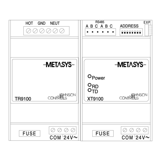
XT-9100 Extension Module/Xp-910X Expansion Modules
Introduction
Hardware Configuration
Model Codes
Software Configuration
XT-9100 Type Settings
XT-9100 Configuration
Analog Input
Digital Input Configuration
Analog Output Configuration
Digital Output Configuration
Download/Upload
Appendix 1: SX Tool Item Description and Tables
General
Item Address
Item Type
Item Tag
Read/Write Data (R/W)
Floating Point Numbers
Item List
Advertisement
Quick Links
1
Xt-9100 Extension Module/Xp-910X Expansion Modules
2
Introduction
3
Hardware Configuration
4
Xt-9100 Type Settings
5
Xt-9100 Configuration
6
Analog Input
7
Digital Input Configuration
Download this manual
XT-9100 Extension Module/XP-910x Expansion Modules
Introduction
Hardware Configuration
Model Codes
Software Configuration
XT-9100 Type Settings
XT-9100 Configuration
Analog Input
Digital Input Configuration
Analog Output Configuration
Digital Output Configuration
Download/Upload
Appendix 1: SX Tool Item Description and Tables
General
Item Address
Item Type
Item Tag
Read/Write Data (R/W)
Floating Point Numbers
Item List
© 1996 Johnson Controls, Inc.
Code No. LIT-6364050
XT-9100 Configuration Guide
System 9100 Technical Manual 636.4
Configuration Guides Section
Configuration Guide
Issue Date 0896
Page
3
3
4
4
7
7
9
10
15
16
19
21
23
23
23
23
24
24
25
25
1
Previous
Page
Next
Page
1
2
3
4
5
Advertisement
Table of Contents
Need help?
Do you have a question about the XP-910x and is the answer not in the manual?
Ask a question
Questions and answers
Related Manuals for Johnson Controls XP-910x
Network Hardware Johnson Controls XT-9100 Configuration Manual
Johnson controls inc. extension module/ expansion module configuration guide (40 pages)
Network Hardware Johnson Controls SNE Series Installation Manual
(29 pages)
Network Hardware Johnson Controls NIE55 Installation Instructions Manual
(14 pages)
Network Hardware Johnson Controls NAE55 Installation Manual
(29 pages)
Network Hardware Johnson Controls Metasys NAE55 Installation Manual
(21 pages)
Network Hardware Johnson Controls S300 Series Hardware Installation
(35 pages)
Network Hardware Johnson Controls D Series Installation Manual
Vfd for d-series (dsv/dsh) air-cooled self-contained units, and c-series (csv) water-cooled self-contained units, cgen (24 pages)
Network Hardware Johnson Controls Facility Explorer Technical Bulletin
Network room module (33 pages)
Network Hardware Johnson Controls Metasys Intelligent Fire Network Technical Manual
(72 pages)
Network Hardware Johnson Controls CK722 Manual
Network controller (32 pages)
Network Hardware Johnson Controls IQ WIFI Installation Manual
(45 pages)
Network Hardware Johnson Controls EasyIO FW Series User Manual
Modbus subordinate (12 pages)
Network Hardware Johnson Controls Tyco exacqVision 2UA Quick Start Manual
(4 pages)
This manual is also suitable for:
Xt-9100
Xt-9100-8004
Xp-9102-8004
Xp-9103-8004
Xp-9104-8004
Xp-9105-8004
...
Show all
Xp-9106-8004
Tr-9100-8001
Tr-9100-8002
Table of Contents
Print
Rename the bookmark
Delete bookmark?
Delete from my manuals?
Login
Sign In
OR
Sign in with Facebook
Sign in with Google
Upload manual
Upload from disk
Upload from URL


Need help?
Do you have a question about the XP-910x and is the answer not in the manual?
Questions and answers