Johnson Controls NAE55 Installation Manual
Hide thumbs
Also See for NAE55:
- Installation instructions manual (14 pages) ,
- Installation manual (37 pages) ,
- Installation instructions manual (15 pages)
Table of Contents
Advertisement
Application
The Metasys
Network Automation Engine (NAE)
®
and Network Integration Engine (NIE) are Ethernet-
based, supervisory devices that connect BAS
networks to IP networks. NAEs and NIEs monitor
and control field-level building automation devices,
including HVAC equipment, lighting, security, and
fire safety equipment. Use this document to install
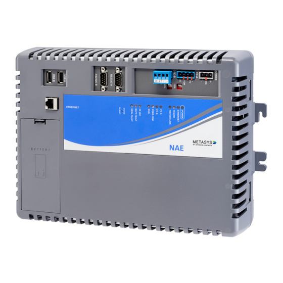
the NAE or NIE. Figure 1 shows the NAE55 engine,
Figure 2 shows the NIE55 engine.
Figure 1: NAE55 Network Engine
Figure 2: NIE55 Network Engine
NAE55/NIE55 Installation Guide
The NAE offers various integration options. Ethernet
network integrations include the following options:
• Johnson Controls and 3rd party BACnet/IP devices
• Simplex
Fire Alarm Control Unit (FACU)
®
• Cree
SmartCast
®
®
• Molex
Lighting Control
®
• Tyco
C•CURE
9000 or victor
®
®
Management
• Modbus TCP/IP
• KNX IP
Field Bus integrations include the following options:
• BACnet MS/TP
• N2 Bus
• LonWorks
®
• Modbus Remote Terminal Unit (RTU)
• Meter Bus (M-Bus)
• Zettler
Fire Panel
®
Important: For any other custom integrations,
contact your local Systems Integration Services
(SIS) team before an upgrade. Updated drivers
are available on request.
In this installation guide, the term network engine
applies to any NAE55 or NIE55 model, unless
otherwise stated. For installation instructions on
the secure NAE55, refer to the NAE-S Installation
Instructions (Part No. 24-10051-108). For installation
instructions on the NAE55s that are approved
for Metasys system smoke control applications,
refer to the NAE55 Installation Instructions (Part No.
24-10051-00132).
Note: The NIE55 network engine is available
at Release 9.0, but beginning at Release 10.0,
the NIE55 is no longer offered. However, repair
models of the NIE55 network engine are still
available. To order a repair NIE55, specify MS-
NIE5510-703 (no modem) or MS-NIE5511-703
(with modem).
Part No. 24-10051-43 Rev. U
Releases 9.0, 10.0, 10.1
2019-10-14
Lighting Control
Video
®
*241005143U*
(barcode for factory use only)
MS-NAE55xx-3,MS-NIE55xx-3
Advertisement
Table of Contents

Related Manuals for Johnson Controls NAE55


Summary of Contents for Johnson Controls NAE55
- Page 1 ® ® including HVAC equipment, lighting, security, and • Molex Lighting Control ® fire safety equipment. Use this document to install the NAE or NIE. Figure 1 shows the NAE55 engine, • Tyco C•CURE 9000 or victor Video ® ®...
-
Page 2: Installation
NAE55 only. engine to Release 10.0 or later. Dimensions Note: If you receive an NAE55 engine from the factory that is imaged with Release 9.0 or 10.0, Figure 3: NAE55 showing dimensions and you can field-upgrade the engine to Release mounting orientation 10.1. -
Page 3: Location Considerations
Each network engine application is different, and no general guidelines can be given about the heat dissipating devices that may be mounted in an enclosure with the network engine. Monitor the network engine processor temperature for each application to determine the acceptable NAE55/NIE55 Installation Guide... - Page 4 1. Snap the DIN clips on the bottom of the the top wall mount feet for horizontal wall network engine to the outward position. mount applications. Hold the network engine in 2. Lift the network engine off the DIN rails. place for vertical application. NAE55/NIE55 Installation Guide...
-
Page 5: Wiring Overview
• Mount the panel in accordance with the manufacturer’s instructions. The two Field Controller (FC) Bus connections on an NAE55 are 4-pin removable, keyed terminal blocks • Mount the network engine in the panel following labeled FC-A and FC-B. the guidelines in the... -
Page 6: Optional Internal Modem
• Do not apply 24 VAC power to the network engine before installing the data protection battery. See the Installing the data protection battery section in this document. NAE55/NIE55 Installation Guide... - Page 7 Controls. • While connecting network devices to 24 VAC power, make sure that transformer phasing is uniform across all devices. Powering network devices with uniform 24 VAC supply power phasing reduces noise, interference, and ground loop problems. NAE55/NIE55 Installation Guide...
- Page 8 In general, the cable should 2. To add additional vendor devices, wire from one not exceed 15 meters for 9600 baud. device to the next in a daisy-chained fashion. Do not connect more than two wires to each terminal. NAE55/NIE55 Installation Guide...
- Page 9 The NAE connects to the M-Bus network devices by using the M-Bus Level Converter. Two components are needed: serial connection cable (INT-DX-KAB01) and the M-Bus Level Converter. (After installation and wiring are complete, refer to the Network Engine Commissioning for M-Bus Vendor Integration NAE55/NIE55 Installation Guide...
- Page 10 For multiple KNX lines, wire from the red and the KNX/IP interface router. (After installation and black terminals on each gateway to the devices wiring are complete, refer to the Network Engine on the same KNX line. NAE55/NIE55 Installation Guide...
-
Page 11: Connecting The Power Source
Commissioning for CREE Digital Lighting Systems Note: Power supply wire colors may be Integration (LIT-12013152) different on transformers not manufactured by Johnson Controls. Follow the transformer • Molex Lighting Control: Metasys System manufacturer’s instructions and the project Commissioning for Molex Digital Lighting Systems installation drawings. -
Page 12: Troubleshooting
The POWER LED goes Off when the data backup is completed. Troubleshooting LED status indicators The LEDs on the front cover of the network engine indicate power and communication status. See Figure 19 and Table 4. NAE55/NIE55 Installation Guide... - Page 13 IP address to the network engine. Then, use the depends on the size of the database and can take network engine's IP address to log on. The network several minutes. engine device object should appear. Figure 19: Network Engine with LED designations NAE55/NIE55 Installation Guide...
- Page 14 PEER COMM (Green) network engine, flashes are more frequent and indicate heartbeat next column) communications from all other network engines on the site. For a single network engine on a network without an ADS, there is no flicker. NAE55/NIE55 Installation Guide...
- Page 15 1000 BaseT: 100 m (330 ft) Cat5E or Cat6 cable Terminations For 10/100/1000 BaseT, no line terminators allowed. Table 6: Guidelines for BACnet protocol MS/TP network topology Category Rules and Maximums Two MS/TP Bus trunks, daisy chain topology only. No T or star topology General configurations. NAE55/NIE55 Installation Guide...
- Page 16 N2 device and a maximum of 50 devices between repeaters 1,500 m (5,000 ft) twisted pair cable without a repeater Line Length and 4,500 m (15,000 ft) twisted pair cable from NAE55 and the farthest N2 device (three Type segments of 1,500 m [5,000 ft] each, separated by repeaters) 2,000 m (6,600 ft) between two fiber modems Solid or stranded 1.0 mm (18 AWG) 3-wire is recommended...
- Page 17 One direct M-Bus (RS-485) connection to either FC Bus port is supported; connection requires an RS485- to-M-Bus Level Converter on the FC Bus port. No restrictions in topology, but bus topology is strongly recommended Number of Devices Depends on level converter, logical maximum is 250 devices. NAE55/NIE55 Installation Guide...
- Page 18 Copper, solid and stranded wires with outer sheath, one- or two-twisted pair; 0.8 to 1.0 mm (20 to 18 AWG) Cable Screen is required and must cover the entire diameter. Drain wire: Diameter minimum 0.5 mm (26 AWG) Termination No termination Manufacturer's At least ISO 9002 Quality Management System NAE55/NIE55 Installation Guide...
- Page 19 Mixed FTT10 and LPT-10/11 Nodes ([FTT10 x 2] + LPT10/11) < 128 Physical Layer Repeaters Maximum of 1 per segment Terminators Two bus type EOL terminators required (NU- Bus Topology EOL202-0) One free topology terminator required (NU- Free Topology EOL203-0) NAE55/NIE55 Installation Guide...
- Page 20 LPT10/11 devices, may limit a segment to fewer devices. • The MS-NAE552x-x models that support LonWorks Network trunks do not have an internal network terminator. Table 15: NAE55 with integrations dual trunk options Trunk Type Supported Dual Trunk Application •...
-
Page 21: Repair Information
Table 16: NAE55-3 ordering information (Release 8.1 or 10.1) Product Code Number Release Description NAE55 Network Automation Engines: Requires a 24 VAC power supply. MS-NAE55xx-x (Base Each model includes two RS-232-C serial ports, two USB serial ports, Features of Each... - Page 22 Rechargeable NiMH battery: 3.6 V 500 mAh, with a typical life of 5 to 7 years at 21°C (70°F) Replacement data protection battery for NAE55 and NIE55. Rechargeable gel MS-BAT1010-0 cell battery: 12 V, 1.2 Ah, with a typical life of 3 to 5 years at 21°C (70°F) Pocket-sized web server that provides a wireless mobile user interface to Metasys field controllers, thermostats, and smart rooftop units.
-
Page 23: Technical Specifications
You can purchase tables from your regional System Integration Services (SIS) office, or you can create the tables with the VMD Generator Express (VGE) tool. To obtain a license, attend the training listed in this table. Technical specifications NAE55/NIE55 Installation Guide... - Page 24 16 GB flash nonvolatile memory for operating system, configuration data, and operations data storage and backup. Memory 2 GB DDR3 SDRAM for operations data dynamic memory for all models Release 9.0: Johnson Controls OEM Version of Microsoft Windows ® ®...
- Page 25 Canada: UL Listed, File E107041, CCN PAZX7, CAN/CSA C22.2 No. 205, Signal Equipment, Industry Canada Compliant, ICES-003 Europe: CE Mark - Johnson Controls, Inc. declares that this product is in compliance with the essential requirements and other relevant provisions of the EMC Directive.
-
Page 26: North American Emissions Compliance
The performance specifications are nominal and conform to acceptable industry standard. For application at conditions beyond these specifications, consult the local Johnson Controls office. Johnson Controls shall not be liable for damages resulting from misapplication or misuse of its products. - Page 27 Your use of this product constitutes an agreement to such terms. Patents Patents: http://jcipat.com NAE55/NIE55 Installation Guide...
- Page 28 © 2019 Johnson Controls. All rights reserved. All specifications and other information shown were current as of document revision and are subject to change without notice. www.johnsoncontrols.com...
Need help?
Do you have a question about the NAE55 and is the answer not in the manual?
Questions and answers