Table of Contents
Advertisement
Introduction to Network Room Module (NRM)..................................... 3
Concepts .............................................................................................................. 4
Features ............................................................................................................................. 4
Controls.............................................................................................................................. 5
Functions and Setup of the Network Room Module........................................................... 6
Network Room Module Parameters (Room Sensor Object) ............................................ 13
Installing and Commissioning the Network Room Module .............. 15
Introduction........................................................................................................ 15
North American Emissions Compliance ........................................................................... 15
Key Concepts..................................................................................................... 16
Location of the Network Room Module ............................................................................ 16
Dimensions of the Network Room Module ....................................................................... 17
Wiring ............................................................................................................................... 18
Addressing ....................................................................................................................... 19
Service Port...................................................................................................................... 20
Commissioning the Network Room Module ..................................................................... 22
Procedure Overview......................................................................................................... 23
Detailed Procedures.......................................................................................... 23
Opening the Network Room Module ................................................................................ 23
Mounting the NRM Directly on a Wall Surface ................................................................. 24
Plastic Base for Surface Mounting ................................................................................... 26
Mounting the NRM (80 x 80 mm) on a Recessed Wall Box ............................................. 27
Commissioning the NRM Module..................................................................................... 29
© 2010 Johnson Controls, Inc.
Code No. LIT-12011258
Network Room Module
Technical Bulletin Network Room Module
Issue Date January 22, 2010
Advertisement
Table of Contents

Related Manuals for Johnson Controls Facility Explorer


Summary of Contents for Johnson Controls Facility Explorer
-
Page 1: Table Of Contents
Mounting the NRM (80 x 80 mm) on a Wall Surface Using the Plastic Base for Surface Mounting ................... 26 Mounting the NRM (80 x 80 mm) on a Recessed Wall Box ..........27 Commissioning the NRM Module..................29 © 2010 Johnson Controls, Inc. Code No. LIT-12011258... - Page 2 Network Room Module Technical Bulletin Troubleshooting ................... 30 Specifications and Ordering Codes............ 31 Specifications and Technical Data..............31 Ordering Codes ....................32 ...
-
Page 3: Introduction To Network Room Module (Nrm)
Fahrenheit (°F) and Celsius (°C) units of measure. The NRM connects to the Remote Display link of the Facility Explorer field controller. Terminals are located in the mounting base for ease of wiring. -
Page 4: Concepts
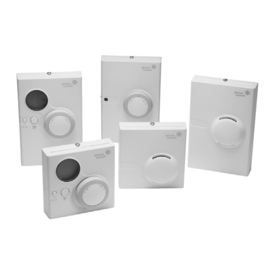
Network Room Module Technical Bulletin Concepts Features The NRM (Figure 2) is styled to blend with the decor of today’s commercial and public buildings. Terminals are located in the mounting base for ease of wiring. The module also has a built-in temperature sensor used to measure space temperature for display and transmission to the connected controller. -
Page 5: Controls
Network Room Module Technical Bulletin The NRM has a service port (located on the lower edge of the module). Use the service port to gain access to the serial bus for the host FX field controller. Two types of service ports are available (see Figure 2 for service port location). -
Page 6: Functions And Setup Of The Network Room Module
Functions and Setup of the Network Room Module The NRM is a network device with no hardware inputs or outputs and connects to the Facility Explorer controller via the display (or local link) bus. All the communication access and setup of the NRM is done through the controller where the NRM is connected. - Page 7 Network Room Module Technical Bulletin See Network Room Module Parameters (Room Sensor Object) for a detailed list of the variables and properties of the NRM. The names of the network variables and configuration properties appear in boldface type throughout this document. Note: After a power failure, the NRM restarts using the values in its configuration properties and any setpoint changes or fan speed overrides...
- Page 8 Network Room Module Technical Bulletin Figure 4: Absolute Setpoint Values in Celsius and Fahrenheit Units Figure 5: Relative (Offset) Setpoint Values in Celsius Units Setpoint Adjustment You can change the value of the setpoint by rotating the NRM dial to the right to increase the setpoint, and to the left to decrease the setpoint.
- Page 9 Network Room Module Technical Bulletin When the fan is set to Auto mode, the Auto symbol appears, and the controller determines the fan speed using its internal control algorithm. Figure 6: Fan Speed Display in Manual Override The fan symbol ( ) is always shown, whether the fan is running or not. Examples of the fan speed display are shown in Table 3.
- Page 10 Network Room Module Technical Bulletin • Three speed If you set the property to Three speed fan, pressing the fan push button cycles the fan status: AUTO, OFF, low, medium, and high speed. Occupancy Mode The LED display indicates the Effective Occupancy Status when the Enable Unoccupied State Blink configuration property is set to enabled (ON) and the network variable input Effective Occupancy Status value shows that the occupancy mode is UNOCCUPIED or STANDBY.
- Page 11 Network Room Module Technical Bulletin Temporary Occupied Mode The Temporary Occupancy Mode Request output network variable normally reflects the value of the Effective Occupancy Status input network variable as received from the controller. In UNOCCUPIED or STANDBY mode, you can force the Temporary Occupancy Mode Request output variable to Temporary Occupied (BYPASS) mode for the time duration (in minutes) set in the configuration property Temporary Occupied Time.
- Page 12 Network Room Module Technical Bulletin Back Light Time-out The LCD is back-lit in the NRM and lights up when the fan or °F/°C push button is pressed or the dial is turned. The back-light time-out is set in the Back-light Time-out configuration property. The factory default setting is 30 seconds.
-
Page 13: Network Room Module Parameters (Room Sensor Object)
Network Room Module Technical Bulletin Network Room Module Parameters (Room Sensor Object) Table 5, Table 6, and Table 7 list the network variables and configuration properties available in the NRM Room Sensor object. You must create an instance of this object in the FX controller for the connected NRM. The controller automatically transfers the configuration data to the NRM module and transmits and receives the network variable information over the local link bus. - Page 14 Network Room Module Technical Bulletin Table 7: Configuration Properties Name/Description Property Name Data Type Default Limits Space Temperature SpaceTempSetptHighLimit Analog - 28.0°C (82.5°F) Max. 40°C (99.5°F) Temperature Setpoint High Limit Space Temperature SpaceTempSetptLowLimit Analog - 12.0°C (53.5°F) Min. 0°C (32.0°F) Temperature Setpoint Low Limit Temporary Occupied...
-
Page 15: Installing And Commissioning The Network Room Module
Network Room Module Technical Bulletin Installing and Commissioning the Network Room Module Introduction The Network Room Module is designed to mount directly on a wall surface in the room you want to control. Separate kits are also available for wall surface mounting with conduits and recessed wall box mounting (see Ordering Codes). -
Page 16: Key Concepts
IMPORTANT: The installation of electrical wiring must conform to local codes and should be carried out by authorized personnel only. Users should ensure that all Johnson Controls® products are used safely and without risk to health or property. -
Page 17: Dimensions Of The Network Room Module
Network Room Module Technical Bulletin Dimensions of the Network Room Module Figure 10: Network Room Module Dimensions, mm (in.) -
Page 18: Wiring
Network Room Module Technical Bulletin Wiring Terminations are made on the terminal block in the base of the module, which is accessible after removing the cover from the base. The screw terminals accept up to 1.5 mm (16 AWG) wires, and Figure 11 shows the terminal block connections. -
Page 19: Addressing
Network Room Module Technical Bulletin Note: The device does not require a ground/earth connection. IMPORTANT: Cables and wiring at Safety Extra Low Voltage (SELV) and Class 2 wiring (North America) must be separated from power line voltage wiring. A minimum separation distance of 30 cm (12 in.) is recommended. Do not run extra low voltage cables parallel to power line voltage cables for long distances greater than 3 m (10 ft). -
Page 20: Service Port
Network Room Module Technical Bulletin Service Port The NRM features a service port which is located on the bottom-right side of the module (Figure 13 and Figure 15). Two types of service ports are supported, depending on the NRM model number. The service port for NRM model LP-NRM0xx-000C is a 4-pin connector and is used for the connection of the FX Programming Key (Figure 14) to download applications to the connected FX field controller over the local... - Page 21 Network Room Module Technical Bulletin The service port for NRM models LP-NRM5xx-000C and LP-NRM6xx-000C is a 6-pin Modular Jack connector and is used for the connection of the Medium User Interface (Figure 15) to provide advanced monitoring and adjustment access to the connected FX field controller over the local link bus.
-
Page 22: Commissioning The Network Room Module
Network Room Module Technical Bulletin Commissioning the Network Room Module General The FX CommPro N2, LON, or BACnet commissioning tool is required to commission the NRM room module and set up the parameters of the module in the connected FX controller. The commissioning tool is connected to the FX controller. -
Page 23: Procedure Overview
To Do This Follow These Steps Open the Room Command Insert the pointed tool or special tool available from Johnson Controls into Module the narrow slot at the center top of the module. While pressing down gently, pry the cover away from the base. In North American models, the anti-tamper screw must first be removed. -
Page 24: Mounting The Nrm Directly On A Wall Surface
Network Room Module Technical Bulletin Figure 16: FX Tool to Open Module 3. While pressing down gently, pry the cover away from the base. As the two parts separate, remove the tool and continue to pull the cover away from the base until the cover is free. 4. - Page 25 Network Room Module Technical Bulletin Figure 17: Module Base Dimensions (80 x 80 mm) Figure 18: Module Base Dimensions (120 x 80 mm)
-
Page 26: Mounting The Nrm (80 X 80 Mm) On A Wall Surface Using The Plastic Base For Surface Mounting
Network Room Module Technical Bulletin Mounting the NRM (80 x 80 mm) on a Wall Surface Using the Plastic Base for Surface Mounting To mount the NRM on a wall surface using the plastic base for surface mounting (see Figure 21 for dimensions): 1. -
Page 27: Mounting The Nrm (80 X 80 Mm) On A Recessed Wall Box
Network Room Module Technical Bulletin OB EN Figure 21: Dimensions (mm) of the Plastic Surface Mounting Base Mounting the NRM (80 x 80 mm) on a Recessed Wall Box To install the recessed wall box mounting kit (see Figure 25 for dimensions): 1. - Page 28 Network Room Module Technical Bulletin Figure 23: Front View of Wall Box Mounting Kit 3. Tighten screws (B) until the prongs clamp properly in the wall box. 4. Mount the base of the module on the kit, as shown in Figure 24, using the two screws included in the kit and inserting them into two opposite holes of the four holes marked (C).
-
Page 29: Commissioning The Nrm Module
Network Room Module Technical Bulletin Commissioning the NRM Module To commission the NRM module: 1. Check the network and power wiring to the NRM module. 2. Turn on the module. If the power comes from the connected FX controller, apply power to the controller. On powerup, the NRM displays all symbols and segments of the display while a self test is performed. -
Page 30: Troubleshooting
Network Room Module Technical Bulletin Troubleshooting Table 10: Troubleshooting NRM Installation Problem Cause/Action No indication is on LCD. No power available. Check the wiring and supply voltage to the module. One or more of the following has occurred: Maintenance icon is visible on •... -
Page 31: Specifications And Ordering Codes
Network Room Module Technical Bulletin Specifications and Ordering Codes Specifications and Technical Data Table 11: Network Room Module Specifications and Technical Data Parameter/Component Value/Description Power Supply 14.3 to 27.6 VDC (15 to 18 VDC from connected FX controller) LP-NRM0xx-000C Series at 500 mW maximum, or 24 VAC ±... -
Page 32: Ordering Codes
Network Room Module Technical Bulletin Parameter/Component Value/Description (Cont.) Shipping Weight 0.2 kg (7 oz.), 80 x 80 mm (3.15 x 3.15 in.) housing or 0.25 kg (9 oz), 120 x 80 mm (4.72 x 3.15 in.) housing Compatible FX06 FX07 FX14 FXVMA FX Controllers and... - Page 33 The performance specifications are nominal and conform to acceptable industry standards. For application at conditions beyond these specifications, consult the local Johnson Controls office. Johnson Controls, Inc. shall not be liable for damages resulting from misapplication or misuse of its products.
Need help?
Do you have a question about the Facility Explorer and is the answer not in the manual?
Questions and answers