Johnson Controls S300 Series Hardware Installation Manual
Hide thumbs
Also See for S300 Series:
- Hardware installation (44 pages) ,
- Hardware installation manual (31 pages) ,
- Hardware installation manual (21 pages)

Related Manuals for Johnson Controls S300 Series


Summary of Contents for Johnson Controls S300 Series
- Page 1 S300 Series S300-DIN-RDR2S Hardware Installation Manual April, 2010 24-10239-413 Revision A...
- Page 2 Controls, Inc. are not intended to duplicate nor replace other manufacturer’s documentation. If this document is translated from the original English version by Johnson Controls, Inc., all reasonable endeavors will be used to ensure the accuracy of translation. Johnson Controls, Inc.
- Page 3 Due to continuous development of our products, the information in this document is subject to change without notice. Johnson Controls, Inc. shall not be liable for errors contained herein or for incidental or consequential damages in connection with furnishing or use of this material. Contents of this publication may be preliminary and/or may be changed at any time without any obligation to notify anyone of such revision or change, and shall not be regarded as a warranty.
- Page 4 UNDERWRITERS LABORATORIES COMPLIANCE VERIFICATION SHEET The following model numbers are listed under Underwriters Laboratories UL 1076 for Proprietary Burglar Alarm Units and Systems and UL 294 for Access Control Systems Units. S300-DIN-RDR2S When installed at the site the following requirements must be met to comply with these standards. The S300-DIN-RDR2S shall be mounted in subassembly S300-DIN-L or S300-DIN-S.
- Page 5 Wiegand Data0 and Data1 interface Door strike relay (SPDT) Alarm shunt relay driver (open collector) Red lamp driver (open collector) Green lamp driver (open collector) 24-10239-413 Rev. A This document contains confidential and proprietary information of Johnson Controls, Inc. © 2010 Johnson Controls, Inc.
-
Page 6: Installation
If the contents of a container are damaged in any way, notify the carrier and your Johnson Controls representative immediately. Report any discrepancies to your Johnson Controls representative. Save the packing materials for possible return shipments. 24-10239-413 Rev. A This document contains confidential and proprietary information of Johnson Controls, Inc. -
Page 7: Package Contents
If DC power has already been connected to the unit, disconnect the DC power before separating the electronics board from the wiring base. CAUTION Electronics Board Guides Guides 24-10239-413 Rev. A This document contains confidential and proprietary information of Johnson Controls, Inc. © 2010 Johnson Controls, Inc. - Page 8 S300-DIN-L-PS and S300-DIN-S-PS model power supplies, refer to the S300-DIN-L Hardware Installation Manual and the S300-DIN-S Hardware Installation Manual. 24-10239-413 Rev. A This document contains confidential and proprietary information of Johnson Controls, Inc. © 2010 Johnson Controls, Inc.
-
Page 9: Din Rail Mounting
Top part Base part Mounting Holes 24-10239-413 Rev. A This document contains confidential and proprietary information of Johnson Controls, Inc. © 2010 Johnson Controls, Inc. -
Page 10: Dc Power Source
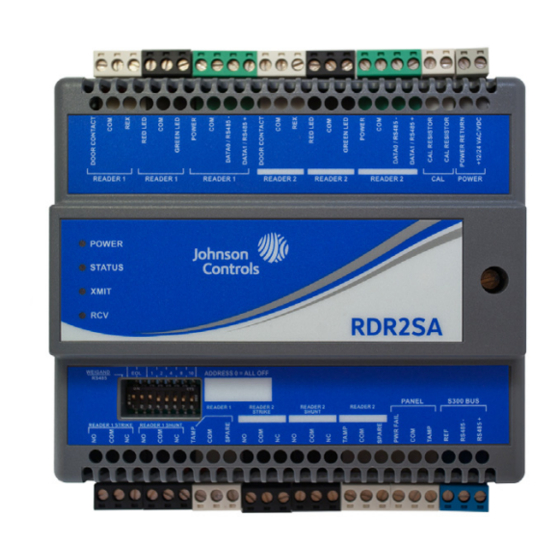
All interface signals are connected via plug-in connectors and terminal blocks. For a description of the RDR2S I/O interface signals, see “Legacy Operation” on page 28. 24-10239-413 Rev. A This document contains confidential and proprietary information of Johnson Controls, Inc. © 2010 Johnson Controls, Inc. - Page 11 S300-DIN-RDR2S Module Hardware Installation 24-10239-413 Rev. A This document contains confidential and proprietary information of Johnson Controls, Inc. © 2010 Johnson Controls, Inc.
- Page 12 Hardware Installation S300-DIN-RDR2S Module 24-10239-413 Rev. A This document contains confidential and proprietary information of Johnson Controls, Inc. © 2010 Johnson Controls, Inc.
-
Page 13: Output Points
(GND). When DRY is selected, the relay is a dry contact relay rated at 2 A at 12 VDC. 24-10239-413 Rev. A This document contains confidential and proprietary information of Johnson Controls, Inc. © 2010 Johnson Controls, Inc. -
Page 14: Cable Requirements
22 AWG Reader (Power) Belden 8760, 1 twisted, Refer to reader manufacturer’s shielded pair, 18 AWG specification for power requirements. 24-10239-413 Rev. A This document contains confidential and proprietary information of Johnson Controls, Inc. © 2010 Johnson Controls, Inc. -
Page 15: Cable Routing
CK720 and the RDR2S. Cut the cable in half and extend the wiring from the CK720 enclosure to the RDR2S. 24-10239-413 Rev. A This document contains confidential and proprietary information of Johnson Controls, Inc. © 2010 Johnson Controls, Inc. -
Page 16: Power Supply
Make sure each wire is connected to the same corresponding connector position in the subsequent RDR2S module. See the following figure for details. CAUTION 24-10239-413 Rev. A This document contains confidential and proprietary information of Johnson Controls, Inc. © 2010 Johnson Controls, Inc. - Page 17 Do not connect the DC power cable to the RDR2S until all wiring is complete. CAUTION If daisy-chain connecting an RDR2S with an S300 Series module (e.g. S300-RDR2, S300-SI8, S300-SIO8, S300-IO8, and S300-I16), wire the devices according to the following illustration.
-
Page 18: Power Requirements
RDR2S in the enclosure, and programmed in the controller. 24-10239-413 Rev. A This document contains confidential and proprietary information of Johnson Controls, Inc. © 2010 Johnson Controls, Inc. - Page 19 Note: The 4-state wiring requires two resistors of the same value. The resistors can be 150-2000 Ohms, 5%, 1/4W. The recommended resistor is 1200 Ohms. 24-10239-413 Rev. A This document contains confidential and proprietary information of Johnson Controls, Inc. © 2010 Johnson Controls, Inc.
- Page 20 General Purpose General Purpose Door Strike Outputs Inputs OUT01 IN01 IN02 OUT02 OUT21 IN21 OUT22 IN22 OUT23 NO / NC (bottom) 24-10239-413 Rev. A This document contains confidential and proprietary information of Johnson Controls, Inc. © 2010 Johnson Controls, Inc.
- Page 21 IN21 (Motion Sensor) DATA0 / DATA1 (bottom), Reader OUT21 and OUT22 Door Contact NO / NC (bottom) Door Strike DOOR 2 24-10239-413 Rev. A This document contains confidential and proprietary information of Johnson Controls, Inc. © 2010 Johnson Controls, Inc.
- Page 22 LEDs lit. When an entity is denied access or egress, both readers will have their red LEDs lit. DOOR (Back) 24-10239-413 Rev. A This document contains confidential and proprietary information of Johnson Controls, Inc. © 2010 Johnson Controls, Inc.
- Page 23 Door Strike Ground and Grounding Cable Shields Ground Every metal DIN enclosure in a Johnson Controls installation must have its chassis bonded to a verified electrical ground (earth). Conduit ground, cold water pipes, unbrazed joints or dissimilar metals are unacceptable in the path of either building or supplemental ground.
- Page 24 2 inches (5 cm) unit 1 UNIT2 Short wire is PCBA connected from shield to enclosure of unit 2 24-10239-413 Rev. A This document contains confidential and proprietary information of Johnson Controls, Inc. © 2010 Johnson Controls, Inc.
- Page 25 AC or DC voltages and transients. 24-10239-413 Rev. A This document contains confidential and proprietary information of Johnson Controls, Inc. © 2010 Johnson Controls, Inc.
-
Page 26: Electronics Board
Data flash LEDs External addressing SRAM Wiegand pair Address lines Output points Door strikes Real time clock Input points UART RS485 24-10239-413 Rev. A This document contains confidential and proprietary information of Johnson Controls, Inc. © 2010 Johnson Controls, Inc. -
Page 27: Configuration Jumpers
+12V +24V +5V Door Strike: Door 2 External Devices: Door 2 Reader Power: Door 2 +12V +24V +12V +24V +12V +5V +24V 24-10239-413 Rev. A This document contains confidential and proprietary information of Johnson Controls, Inc. © 2010 Johnson Controls, Inc. - Page 28 Before changing the EOL position, remove the 24 VDC supply power to the RDR2S and wait for the Power LED to go off. 24-10239-413 Rev. A This document contains confidential and proprietary information of Johnson Controls, Inc. © 2010 Johnson Controls, Inc.
-
Page 29: Baud Rates
Switch positions 1 to 3, switch position 8 OFF CK721 Switch positions 1 to 3, switch position 8 OFF CK720/CK705 Switch positions 1 to 3, switch position 8 OFF 24-10239-413 Rev. A This document contains confidential and proprietary information of Johnson Controls, Inc. © 2010 Johnson Controls, Inc. - Page 30 “Output Point Signals 9 & 10 (CK721-A/CK721/CK720/CK705 11 & 12 Controllers)” on page 31 for details 13 & 14 15 & 16 24-10239-413 Rev. A This document contains confidential and proprietary information of Johnson Controls, Inc. © 2010 Johnson Controls, Inc.
- Page 31 S300-DIN-RDR2S Module Hardware Installation Table 2: CK722 Controllers RDR2S SW3 Settings Hardware Module Address Mode Number (currently not used) 24-10239-413 Rev. A This document contains confidential and proprietary information of Johnson Controls, Inc. © 2010 Johnson Controls, Inc.
- Page 32 RDR map disabled, I/O map enabled RDR map enabled, I/O map disabled RDR map, general purpose output, and general purpose input enabled 24-10239-413 Rev. A This document contains confidential and proprietary information of Johnson Controls, Inc. © 2010 Johnson Controls, Inc.
- Page 33 1. Input is associated with input point 18 Configuration can be 2-state or (forced door) and 24 (propped door). 4-state. 24-10239-413 Rev. A This document contains confidential and proprietary information of Johnson Controls, Inc. © 2010 Johnson Controls, Inc.
- Page 34 Input is logically mapped to connector IN01. connector IN01. Configuration can be 2-state or Configuration can be 2-state or 4-state. 4-state. 24-10239-413 Rev. A This document contains confidential and proprietary information of Johnson Controls, Inc. © 2010 Johnson Controls, Inc.
- Page 35 2. It can be timed, set, reset, fast flash, or slow flash. Output is an open collector that switches to ground. 24-10239-413 Rev. A This document contains confidential and proprietary information of Johnson Controls, Inc. © 2010 Johnson Controls, Inc.
- Page 36 3. It can be timed, set, reset, fast flash, or slow flash. Output is an open collector that switches to ground. 24-10239-413 Rev. A This document contains confidential and proprietary information of Johnson Controls, Inc. © 2010 Johnson Controls, Inc.
- Page 37 Output is an open collector that Output is an open collector that switches to ground. switches to ground. 24-10239-413 Rev. A This document contains confidential and proprietary information of Johnson Controls, Inc. © 2010 Johnson Controls, Inc.
- Page 38 See “General Input Wiring” on page 15 for reference. 24-10239-413 Rev. A This document contains confidential and proprietary information of Johnson Controls, Inc. © 2010 Johnson Controls, Inc.
-
Page 39: Specifications
The environment class for the RDR2S product controller is class 2. The terminal is expected to operate at moderate temperature variation, non-condensing humidity variation, moderate vibration, and possible dust contamination. 24-10239-413 Rev. A This document contains confidential and proprietary information of Johnson Controls, Inc. © 2010 Johnson Controls, Inc. -
Page 40: Specification
Sonic PS-1270, 12 VDC, 7 Ah for the large enclosure; Power Sonic PS-1228, 12 VDC, 2.8 Ah for the small enclosure). 24-10239-413 Rev. A This document contains confidential and proprietary information of Johnson Controls, Inc. © 2010 Johnson Controls, Inc. -
Page 41: Testing Procedure
4. With your free hand gently move the battery out of the holder while keeping the battery pried up. 5. Dispose of the old battery according to local requirements. 24-10239-413 Rev. A This document contains confidential and proprietary information of Johnson Controls, Inc. © 2010 Johnson Controls, Inc. -
Page 42: Field Servicing
Power supply, 24 VDC out, 110 VAC in. S300-DIN-S-PS Power supply, 24 VDC out, 24 VAC in. S300-XFMR Plug-in transformer, 24 VAC, 50VA. 24-10239-413 Rev. A This document contains confidential and proprietary information of Johnson Controls, Inc. © 2010 Johnson Controls, Inc. - Page 43 2. Remove the nut securing the switch to the bracket. 3. Replace the switch and secure it with the nut. 4. Wire the tamper switch to a RDR2S input point. 24-10239-413 Rev. A This document contains confidential and proprietary information of Johnson Controls, Inc. © 2010 Johnson Controls, Inc.
-
Page 44: Troubleshooting
• Defective keypad Card or data loss from database • Noise on power line • Improper grounding • Defective CK720 board 24-10239-413 Rev. A This document contains confidential and proprietary information of Johnson Controls, Inc. © 2010 Johnson Controls, Inc. - Page 45 • Defective Reader Add-on board Holiday time zones not followed • Improperly programmed Holiday time zones or Holi- day dates. 24-10239-413 Rev. A This document contains confidential and proprietary information of Johnson Controls, Inc. © 2010 Johnson Controls, Inc.
- Page 46 Hardware Installation S300-DIN-RDR2S Module 24-10239-413 Rev. A This document contains confidential and proprietary information of Johnson Controls, Inc. © 2010 Johnson Controls, Inc.
Need help?
Do you have a question about the S300 Series and is the answer not in the manual?
Questions and answers