Table of Contents
Advertisement
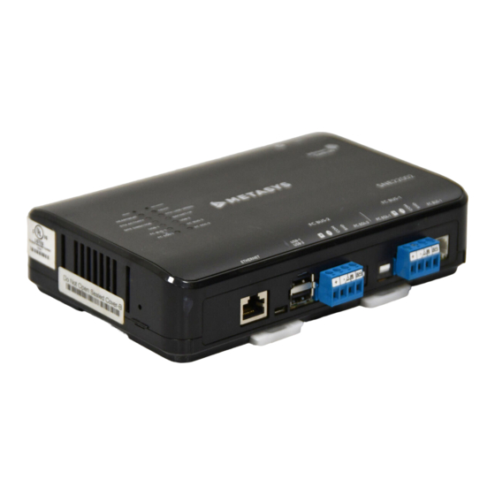
Application
The Metasys SNE Series of Network Engines are Ethernet-
based, supervisory devices that connect BAS networks to
IP networks. These devices monitor and control field-level
building automation devices that include HVAC, lighting,
security, and fire safety equipment.
In addition to providing general comprehensive
equipment monitoring and control, network engines also
offer specialized capabilities by series and model to meet a
variety of application requirements. The following models
are available (where x = 0, 1, or 2):
• SNE2200x-0: succeeds NAE55 Series of network
engines.
• SNE1100x-0: succeeds NAE45 Series of network
engines.
• SNE1050x-0: succeeds NAE35 Series of network
engines.
• SNE110Lx-0: succeeds NAE45-Lite Series of network
engines.
The SNE offers various integration options. Ethernet
network integrations include the following options:
• Johnson Controls and 3rd party BACnet/IP devices
- Simplex
Fire Alarm Control Unit (FACU)
®
- Molex
Lighting Control
®
- Cree
SmartCast
®
• BACnet/SC
• MQ Telemetry Transport (MQTT)
• Tyco
C•CURE
9000 or victor
®
®
• Modbus TCP/IP
• KNX IP
• OPC Unified Architecture (UA)
Field Bus integrations include the following options:
• BACnet MS/TP
• N2 Bus
• LonWorks
with USB adapter
®
• Modbus Remote Terminal Unit (RTU) with USB adapter
• Meter Bus (M-Bus)
• Zettler
Fire Panel
®
See
Wiring considerations and guidelines
of all integrations available for each SNE.
Supported firmware versions
The following table lists the supported firmware versions
of Metasys Release 10.1.x and 11.0.x for the various SNE or
SNC (SNx) models. You may load an SNx with a firmware
version that is at or later than the releases listed in the
table below. For example, if you have an SNExxxx1-x at
Release 10.1.2.73, you can upgrade to Release 11.0.0.1717.
Do not load a firmware version that does not meet the
criteria in the table below.
Lighting Control
®
Video Management
®
for a summary
SNE Installation Guide
For more information about the supported firmware
versions, refer to the Flash Sheet 2022F15 and Flash Sheet
2022F19.
Table 1: SNE/SNC supported releases
Models
Manufacturi
ng date
codes
M4-SNExxxx0-
All
x, M4-
SNCxxxx0-x
M4-SNExxxx1-
Prior to
x, M4-
RY12140
SNCxxxx1-x
M4-SNExxxx1-
Between
x, M4-
RY12140 and
SNCxxxx1-x
RY12207
M4-SNExxxx1-
RY12208 and
x, M4-
newer
SNCxxxx1-x
M4-SNExxxx2-
All
x, M4-
SNCxxxx2-x
Note: You can find the date code sticker either on
the side of the unit, or the underside of the unit. The
date is also located on the shipping box label.
Installation
Follow these guidelines when installing a network engine:
• Transport the network engine in the original container
to minimize vibration and shock damage to the network
engine.
• Verify that all the parts shipped with the network
engine are present.
• Do not drop the network engine or subject it to physical
shock.
Important: Do not open the network engine
housing for any reason. The network engine has no
user-serviceable parts inside. Tamper-evident labels
on the device caution installers, service technicians,
building owners, and our RMA inspectors from
unauthorized opening or tampering of the device.
Parts included
• One SNE network engine
• One QR code SNE Pack Sheet (Part No.A163816VBR)
*241014301647G*
M4-SNE22000-0, M4-SNE11000-0, M4-SNE10500-0,
M4-SNE110L0-0, M4-SNE22001-0, M4-SNE11001-0,
Part No. 24-10143-01647 Rev. G
Release 12.0
2022-12-12
Supported releases
10.1.x
11.0.x
10.1.0.1757
11.0.0.1717
or later
or later
10.1.2.73 or
11.0.0.1717
later
or later
10.1.5.135
11.0.2.341
or later
or later
10.1.5.135
11.0.2.341
or later
or later
10.1.5.135
11.0.2.341
or later
or later
(barcode for factory use only)
M4-SNE10501-0, M4-SNE110L1-0
Advertisement
Table of Contents

Related Manuals for Johnson Controls SNE Series


Summary of Contents for Johnson Controls SNE Series
- Page 1 Application For more information about the supported firmware versions, refer to the Flash Sheet 2022F15 and Flash Sheet The Metasys SNE Series of Network Engines are Ethernet- 2022F19. based, supervisory devices that connect BAS networks to Table 1: SNE/SNC supported releases IP networks.
-
Page 2: Physical Features
A ports. The USB-1 port can use any Johnson Controls approved USB device; USB-2 port The accompanying table provides a description of the can use any non-wireless, Johnson Controls physical features and a reference to further information approved USB device. See ports. -
Page 3: Location Considerations
Table 2: Physical features of the SNE To mount the SNE to a DIN rail, complete the following steps: Callout Physical features Securely mount a 19.0 cm (7.5 in.) or longer section • SNE22000 One Ethernet port; of 35 mm (1 1/8 in.) DIN rail in the required space. 1000/100/10 Mbps;... -
Page 4: Wiring Overview
Wiring overview • Molex Lighting Control • OPC Unified Architecture (UA) Power supply, network, and • MQTT communication connections Note: The SNE network engine supports maximum one MQTT Client application. See Figure 2 for the location of the power supply terminal, network communication terminals, Ethernet jack, and USB FC Bus terminal blocks connections. - Page 5 USB ports of the SNE, but components carrying hazardous voltage can cause Johnson Controls will continue to qualify additional adapters in future releases. Also, the USB ports do electric shock and may result in severe personal injury not support external modems or USB network hubs.
- Page 6 Power, FC Bus, and and the project installation drawings. Power supply SA Bus terminal block wire colors may be different on transformers not manufactured by Johnson Controls replacement kit for ® SNC, CGM, and CVM • Verify that transformer phasing is uniform across the devices.
- Page 7 protocol. The FC bus port pin assignment is shown in the Figure 5: FC Bus terminal blocks and wiring following figure. connections (SNE22000 shown) Figure 4: Pin number assignments for FC Bus port on Set the FC EOL-1 and FC EOL-2 switches to the proper positions.
- Page 8 wired between the USB port and the LON network. (After Go to Connecting the power source. installation and wiring are complete, refer to the LonWorks Connecting Modbus RTU devices Network Integration with NAE and LCS Technical Bulletin (LIT-1201668) for additional information.) About this task: The SNE connects to Modbus RTU devices directly if the Connect the 2-wire cable from the LonWorks...
- Page 9 Figure 10: Connecting SNE to M-Bus Network using M- Table 9: Modbus Adapter connection detail Bus Adapter Callout Description USB connection: Connect USB cable from SNE to RS-232 converter USB-to-RS-232 adapter To Modbus devices FC Bus terminal connection To add additional vendor devices, wire from one device to the next as shown below.
- Page 10 Table 11: M-Bus Level Converter connection Note: Use the RS-232 adapter described in this section if you are replacing an NAE with an SNE detail model, and you used the M-Bus Level Converter for Callout Description integrating the M-Bus network to the NAE's RS-232 port.
-
Page 11: Connecting The Power Source
See Wiring be different on transformers not considerations and guidelines for network manufactured by Johnson Controls. integrations. Follow the transformer manufacturer’s Wire each KNX gateway to its own dedicated power instructions and the project installation supply on the KNX line. -
Page 12: Troubleshooting
connections that sets the engine as a network terminated Note: The behavior of the super capacitor is device on the bus. different from backup batteries that network engines have used in the past. For example, the To set a network engine as an FC Bus terminated device, capacitor requires time to recharge after each power position the switch on the EOL switch block to the ON cycle. - Page 13 Table 13: Network Engine LEDs designation, normal status, description, and other conditions LED Name Color State Description HEARTBEAT Multicolor: Flashing 1 blink per second = Normal operating status (all monitored blue or blue and processes have started and the device is fully operational) purple purple On, blue...
-
Page 14: Reset Button
Table 13: Network Engine LEDs designation, normal status, description, and other conditions LED Name Color State Description No data transmission FC BUS-2 Green Flashing 1 blink per second = data transmission with normal communication over FC BUS-2 Network engines are defined on FC BUS-2, but none are communicating. - Page 15 Defaults the engine's hostname to SNE and MAC Note: To determine which partition is currently address. active, open the Metasys SMP UI in Expert mode and locate the Update object of the SNE Defaults the IP address to DHCP. under All items > Expert. The Active System Reverts to the factory default security database.
- Page 16 Table 16: Guidelines for N2 network topology Category Rules/maximums allowed General SNE2200x model supports two N2 Bus trunks. SNE1100x and SNE1050x models support one N2 Bus trunk. Note: The SNE110Lx model does not support the N2 BusOnly daisy-chained N2 devices (with maximum stub length of 3 m [10 ft] to any device) Number of devices SNE2200x model: supports up to 100 N2 devices per N2 Bus, with no more than two...
- Page 17 Table 19: Maximum number of devices per LonWorks network trunk Device type Maximum allowed SNE2200x model Supports one LonWorks network trunk with up to 255 LONWORKS devices (maximum) SNE1100x models Supports one LonWorks network trunk with up to 127 LONWORKS devices (maximum) Note: The SNE110Lx model does not support the LonWorks network interface.
- Page 18 Table 21: M-Bus protocol rules (bus topology) Category Rules General Two direct M-Bus connections to the USB port are supported. Connection requires a USB-to-M-Bus adapter at the USB port Either FC port supports M-Bus devices No restrictions in topology, but bus topology is strongly recommended Number of devices The MR003USB adapter supports up to 10 loads The ACC-USBMBUS-0 adapter supports up to 100 loads...
- Page 19 Drain wire: Diameter minimum 0.5 mm (26 AWG) Termination No termination Manufacturer's quality At least ISO 9002 management system SNE capabilities Table 23: SNE series network engine details: SNE2200x, SNE1100x, SNE1050x, SNE110Lx Features SNE2200x SNE1100x SNE1050x SNE110Lx Succeeds NAE55 Series...
- Page 20 Table 23: SNE series network engine details: SNE2200x, SNE1100x, SNE1050x, SNE110Lx Features SNE2200x SNE1100x SNE1050x SNE110Lx BACnet MS/TP maximum devices per trunk (Johnson Controls devices only) Note: A repeater is required if more than 50 Johnson Controls devices are on the same trunk.
- Page 21 Table 23: SNE series network engine details: SNE2200x, SNE1100x, SNE1050x, SNE110Lx Features SNE2200x SNE1100x SNE1050x SNE110Lx Supported integrations • BACnet/SC • BACnet/IP - Simplex Fire Alarm Control Unit (FACU) ® - Cree SmartCast Lighting Control ® ® - Molex Lighting Control ®...
- Page 22 Table 24: SNE ordering information Product code number Description M4-SNExxxxx-xxx SNE Supervisory Network Engine Series (base features of each SNE) Requires a 24 VAC or 24 VDC power supply. Each model includes one Ethernet port, one RS-485 communications port, two standard USB serial ports, and one micro-USB port (future use).
-
Page 23: Accessories Ordering Information
Accessories ordering information Table 26: SNE accessories ordering information Product code number or vendor Description model number AS-XFR100-1 Power transformer with enclosure, class 2, 24 VAC, 92 VA maximum output. AS-XFR010-1 Power transformer, no enclosure, class 2, 24 VAC, 92 VA maximum output. ACC-PWRKIT-1A24 Power supply, desktop kit, 90-264 VAC to 24 VDC, 65 W, includes AC cord with North American Plug. -
Page 24: Repair Information
KNX IP router to connect KNX line through Ethernet to a network engine, including line or area coupler functionality Note: For the European market, order these KNX accessories in AOMS from the Johnson Controls European Distri- bution Center. Note: When you use the GRIPIN01-S-KNX for SNx integration, use the non-secure mode. Set the Metasys driver to N=ROUTING MODE, and in ETS set the Secure mode to deactivated. - Page 25 Canada: UL Listed, File E107041, CCN PAZX7, CAN/CSA C22.2 No. 205, Signal Equipment; Industry Canada Compliant, ICES-003 Europe: CE Mark – Johnson Controls, Inc. declares that this product is in compliance with the essential requirements and other relevant provisions of the EMC Directive.
- Page 26 Canada: UL Listed, File E107041, CCN PAZX7, CAN/CSA C22.2 No. 205, Signal Equipment; Industry Canada Compliant, ICES-003 Europe: CE Mark – Johnson Controls, Inc. declares that this product is in compliance with the essential requirements and other relevant provisions of the EMC Directive.
-
Page 27: Contact Information
Changes or modifications not expressly approved by the party responsible for compliance could void the user’s product constitutes an agreement to such terms. authority to operate the equipment. Patents Patents: https://jcipat.com Contact information Contact your local branch office: www.johnsoncontrols.com/locations Contact Johnson Controls: www.johnsoncontrols.com/ contact-us SNE Installation Guide... - Page 28 © 2022 Johnson Controls. All rights reserved. All specifications and other information shown were current as of document revision and are subject to change without notice. www.johnsoncontrols.com...
Need help?
Do you have a question about the SNE Series and is the answer not in the manual?
Questions and answers