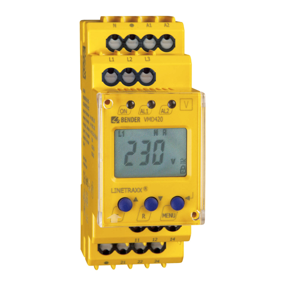
Bender VMD420 Manual
Voltage and frequency monitor
Hide thumbs
Also See for VMD420:
- Manual (60 pages) ,
- Installation bulletin and reference manual (2 pages) ,
- Quick start manual (8 pages)

Related Manuals for Bender VMD420


Summary of Contents for Bender VMD420
- Page 1 VMD420 Voltage and frequency monitor for monitoring of 3(N)AC systems up to 0…500 V for undervoltage, overvoltage, underfrequency, overfrequency VMD420_D00137_03_M_XXEN/03.2020 Manual EN...
- Page 2 Service and support for Bender products First-level support Technical support Carl-Benz-Strasse 8 • 35305 Grünberg • Germany Telephone: +49 6401 807-760 0700BenderHelp * Fax: +49 6401 807-629 E-mail: support@bender-service.de Available on 365 days from 7.00 a.m. to 8.00 p.m. (MEZ/UTC +1) * Landline German Telekom: Mon-Fri from 9.00 a.m.
-
Page 3: Table Of Contents
Indication of important instructions and information ........5 1.2.1 Signs and symbols ......................5 Training courses and seminars.................5 Delivery conditions .......................5 Inspection, transport and storage ................6 Warranty and liability....................6 Disposal of Bender devices ..................6 Safety ..........................6 Function ....................9 Device features ......................9 Function ..........................9 2.2.1 Preset function .......................9 2.2.2... - Page 4 Calling up or leaving the menu ................24 Carrying out settings in the menu ............... 24 4.8.1 Select menu items ..................... 24 4.8.2 Carrying out settings in the menu item AL ............25 4.8.3 Carrying out settings in the menu item out ............ 28 4.8.4 Carrying out settings in the menu item t ............
-
Page 5: General Instructions
Training courses and seminars www.bender.de > Know-how-> Seminars. Delivery conditions The conditions of sale and delivery set out by Bender apply. These can be obtained from Bender in printed or electronic format. The following applies to software products: “Software clause in respect of the licensing of standard software as part of de-... -
Page 6: Inspection, Transport And Storage
• Non-observance of technical data. • Repairs carried out incorrectly. • Use of accessories and spare parts not recommended by Bender. • Catastrophes caused by external influences and force majeure. • Mounting and installation with device combinations not recommended by the manufac- turer. - Page 7 VMD420 Before installing and connecting the device, make sure that the installation has been de-ener- gised. The rules for working on electrical systems must be observed. VMD420_D00137_03_M_XXEN/03.2020...
- Page 8 Function VMD420_D00137_03_M_XXEN/03.2020...
-
Page 9: Function
VMD420 Function Device features • VMD420 requires separate supply voltage Us • Undervoltage, overvoltage, underfrequency and overfrequency monitoring of 3(N)AC systems up to AC 0…500 V / 0…288 V • Asymmetry, phase failure and phase sequence monitoring • Start-up delay, response delay and delay on release adjustable •... -
Page 10: Automatic Self Test
2.2.4 Functional faults If an internal malfunction occurs, all three LEDs flash. An error code will appear on the display (E01…E32). In such a case please contact the Bender Service. 2.2.5 Fault memory VMD420_D00137_03_M_XXEN/03.2020... -
Page 11: Assigning Alarm Categories To Alarm Relays K1/K2
When password protection is enabled (on), settings can only be carried out after ntering the pass- word (0…999). If you cannot operate your device because you cannot remember your password, please contact info@bender-service.com. 2.2.9 Factory setting FAC After activating the factory setting, all settings previously changed are reset to delivery status. In... -
Page 12: Alarm Leds Show Which Relay Is In The Alarm State
Function 2.2.11 Alarm LEDs show which relay is in the alarm state When the menu item LEd is activated, the alarm LED AL1 indicates that K1 is in the alarm state. When AL2 lights up, K2 is in the alarm state. An alarm relay cannot switch to the alarm state unless an alarm category has been assigned to it. - Page 13 VMD420 2.2.13 Frequency alarm in case of measuring voltage failure (MenU -> AL -> <U Hz) If the voltage of the monitored system falls to the point where the frequency can no longer be determined, this parameter is used to set how the frequency alarm should behave.
- Page 14 Installation, connection and comissioning VMD420_D00137_03_M_XXEN/03.2020...
-
Page 15: Montage, Anschluss Und Inbetriebnahme
VMD420 Installation, connection and comissioning of electrocution due to electric shock! Touching live parts of the system carries the risk of an electric shock, damage to the electrical installation or destruction of the device Before in- stalling and connecting the device, make sure that the installation has been de-energised. -
Page 16: Installation
Installation, connection and comissioning Installation Dimensions 36 mm Mounting Click & Click! Abb. 3–1 Variant A: DIN rail mountig, Variant B: Screw mounting VMD420_D00137_03_M_XXEN/03.2020... -
Page 17: Wiring Diagram
Prior to commissioning make sure aterial that the device is properly connected!! After connecting a brand-new VMD420… to a standard system of U = 400 V 50 Hz, the res- ponse values are automatically set by the internal preset function:... - Page 18 Installation, connection and comissioning During the first start-up process the following response values are automatically set related to U Response value overvoltage (> U) 1.1 U Response value undervoltage (< U) 0.85 U Hysteresis U Underfrequency < Hz Overfrequency > Hz Hysteresis frequency (Hys Hz) 0.2 Hz Frequency alarm (<...
- Page 19 VMD420 User settings Menu Parameter FAC¹ User setting Setting range AL-LED < U PRESET > U PRESET 500 V U Hys 1 %. . . 40 % 5 %. . . 30 % 1+2* < Hz PRESET 10 Hz 1+2* >...
-
Page 20: Eigene Einstellungen
Installation, connection and comissioning Menu Parameter FAC* Eigene Einstellungen / Einstellbereich / AL-LED User setting Setting range 0 s. . . 300 s 0,5 s 0 s. . . 300 s L1, L2, L3 3Ph / 3 n 3Ph / 3 n ¹... -
Page 21: Operating And Setting
VMD420 Operating and setting Getting to know the user interface Device front Element Function Power On LED, green Menu item LEd deactivated: LED Alarm 1 lights (yellow): Response value > U exceeded, LED Alarm 2 lights (yellow): Response value < U reached... -
Page 22: Keys And Key Functions
Operating and setting Standard display indications DISPLAY PHASE-TO-PHASE DISPLAY TYPE OF VOLTAGE: CONDUCTORS L1-L3: Displays the type of voltage. Displays active phase- to-pha- se conductors. DISPLAY ASYMMETRY: PASSWORD PROTECTION Displays the asymmetry value ENABLED: in %. Indicates that password pro- tection is activated. -
Page 23: Query Values
VMD420 ENTER • Call up menu, submenu. • Save changed parameter value. • Keep key pressed for more than 1.5 seconds: Call up/leave the menu/ move to the next higher submenu item.. Query values By default, the display shows the phase-to-phase voltage between L1 and L2. By pressing the UP and DOWN key, the phase-to-phase voltage between L1 and L3, L2 and L3 as well as asymmetry, system frequency and phase sequence can be queried. -
Page 24: Deactivating Fault Memory
Operating and setting Deactivating fault memory The device utilises an erasable fault memory. In order to clear the fault memory: • Keep the key pressed for more than 1.5 seconds. Calling up or leaving the menu • To call up the menu: Keep the key pressed for more than 1.5 seconds. -
Page 25: Carrying Out Settings In The Menu Item Al
VMD420 Set delays: • Response delay t • Start-up delay t • Delay on release t (LED, relay Set the parameters for device control • Select method of measurement 3Ph or 3n • Enable or disable password protection, change pass word ... - Page 26 Operating and setting Menu item AL Select submenu Activate/ Change Change/save item deactivate para- display para- parameter meters meter value Set the the response value for undervoltage Set the response value for overvoltage Set the hysteresis for voltage response values Set the asymmetry response value Set the response value...
- Page 27 VMD420 Menu item AL Select submenu Activate/ Change Change/save item deactivate para- display para- parameter meters meter value Set the response value for overfrequency Set the hysteresis for frequency response value Set frequency alarm in case of measuring voltage <...
-
Page 28: Carrying Out Settings In The Menu Item Out
Operating and setting 4.8.3 Carrying out settings in the menu item out 1. Select menu item out. 2. Carry out parameter change as illustrated below. 3. Keep the key pressed for more than 1.5 seconds to return to the menu item level af- ter parameter change. - Page 29 VMD420 Menu item out Select submenu Activate/ Change Change/save item deactivate para- display para- parameter meters meter value Setting the alarm relay K1 to N/C operation (n.c.) Reset alarm relay K1 to N/O operation (n.o.) Select submenu item Reset alarm relay K2 to N/ O operation (n.o.)
- Page 30 Operating and setting Menu item out Select submenu Activate/ Change Change/save item deactivate para- display para- parameter meters meter value LEDs AL1/ AL2 indicate alarm state of K1/K2 Select submenu item Assign category device error to alarm relay K1 Change category Assign undervoltage fault to alarm relay K1...
- Page 31 VMD420 Menu item out Select submenu Activate/ Change Change/save item deactivate para- display para- parameter meters meter value Assign overfrequency fault to alarm relay K1 Change category Assign phase sequence fault to alarm relay K1 Change category Assign undervoltage fault to alarm relay K1...
-
Page 32: Carrying Out Settings In The Menu Item T
Operating and setting 4.8.4 Carrying out settings in the menu item t 1. Select menu item t. 2. Carry out parameter change as illustrated below. 3. Keep the key pressed for more than 1.5 seconds to return to the menu item level af- ter parameter change.. - Page 33 VMD420 Menu item SEt Select submenu Activate/ Change Change/save item deactivate para- display para- parameter meters meter value Set method of measure- ment for phase Select submenu item Enable password pro- tection and enter pass- word (3-digit numerical code) Change password...
- Page 34 Operating and setting Menu item SEt Select submenu Activate/ Change Change/save item deactivate para- display para- parameter meters meter value Disable password protection Select submenu item Re-establish factory settings Select submenu item Automatically reset to factory settings VMD420_D00137_03_M_XXEN/03.2020...
-
Page 35: Querying Information In Menu Item Inf
VMD420 Menu item SEt Select submenu Activate/ Change Change/save item deactivate para- display para- parameter meters meter value Activate preset function for 3Ph and 3n manually Select submenu item The texts „run“ and “PrE“ will alternately appear on the display. -
Page 36: Querying And Clearing Fault Memory In The Menu Item His
Operating and setting 4.8.7 Querying and clearing fault memory in the menu item HIS 1. Select menu item HIS. 2. Change parameters according to table. 3. Keep the key pressed for more than 1.5 seconds to return to the menu item level af- ter parameter change. -
Page 37: Technical Data
VMD420 Technical Data Data in tabular form Insulation coordination acc. to IEC 60664-1/IEC 60664-3 Rated insulation voltage .................................. 400 V Rated impulse voltage/pollution degree ............................4 kV/III Protective separation (reinforced insulation) between . (A1, A2) - (N, L1, L2, L3) - (11, 12, 14) - (21, 22, 24) Voltage test acc. - Page 38 Technical Data Preset function: Underfrequency for f = 16.7 Hz/50 Hz/60 Hz/400 Hz .................15.7 Hz/49 Hz/59 Hz/399 Hz Overfrequeny for f = 16.7 Hz/50 Hz/60 Hz/400 Hz ..................17.7 Hz/51 Hz/61 Hz/401 Hz Hysteresis frequency Hys Hz ............................ 0.1…2 Hz (0.2 Hz)* Relative percentage error in the frequency range of 15…460 Hz................
- Page 39 VMD420 Classification of mechanical conditions acc. to IEC 60721: Stationary use (IEC 60721-3-3) ................................ 3M11 Transport (IEC 60721-3-2) ................................. 2M4 Long-term storage (IEC 60721-3-1) ..............................1M12 Option „W“ data different from the standard version Classification of climatic conditions acc. to IEC 60721: Stationary use (IEC 60721-3-3) ..
-
Page 40: Ordering Information
Nachdruck und Vervielfältigung Reprinting and duplicating nur mit Genehmigung des Herausgebers. only with permission of the publisher. Bender GmbH & Co. KG Bender GmbH & Co. KG Postfach 1161 • 35301 Grünberg • Deutschland PO Box 1161 • 35301 Grünberg • Germany Londorfer Str.
Need help?
Do you have a question about the VMD420 and is the answer not in the manual?
Questions and answers