Table of Contents

Related Manuals for Bender VMD421H


Summary of Contents for Bender VMD421H
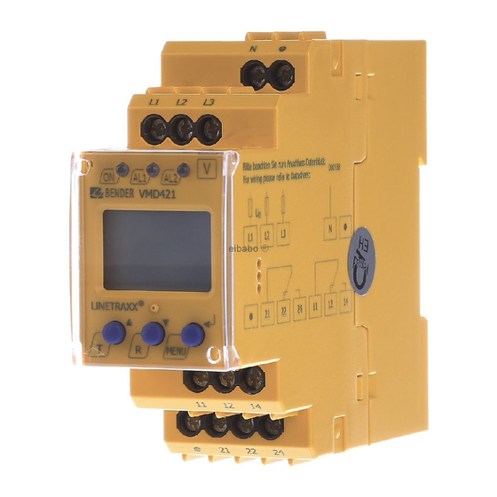
- Page 1 Operating manual VMD421H Voltage and frequency monitor for undervoltage, overvoltage, underfrequency and overfrequency monitoring in 3(N)AC systems of 70...500 V Software version D239 V1.21 Power in electrical safety TGH1405en/01.2007...
- Page 2 Dipl.-Ing. W. Bender GmbH & Co.KG Londorfer Str. 65 • 35305 Grünberg • Germany Postfach 1161 • 35301 Grünberg • Germany Tel.: +49 (0)6401-807-0 Fax: +49 (0)6401-807-259 E-Mail: info@bender-de.com Web-Server: http://www.bender-de.com © Dipl.-Ing. W. Bender GmbH & Co.KG All rights reserved.
-
Page 3: Table Of Contents
Table of Contents 1. How to use this documentation effectively ..........5 How to use this manual ................. 5 Intended use ...................... 5 Fast commissioning for Un = 400 V, 50 Hz ..........5 2. Safety information ................... 7 Safety instructions ................... 7 Work activities on electrical installations .......... - Page 4 5.5.11 Device information query ................37 5.5.12 History memory query ................. 37 Commissioning ....................37 Preset function/ factory setting ............... 38 6. Technical data VMD421H ................39 Data in tabular form ..................39 Ordering information ................... 42 Voltage timing diagram ................43 Timing diagram: asymmetry, phase failure, phase sequence ..
-
Page 5: How To Use This Documentation Effectively
Info symbol. 1.2 Intended use The voltage monitor VMD421H monitors 3(N)AC systems in the fre- quency range 15...460 Hz for undervoltage, overvoltage, underfrequen- cy and overfrequency. The devices are designed for the nominal voltage range U = 70...500 V. - Page 6 3. When the conditions 1 and 2 are satisfied, you can connect the voltage monitor to the three-phase system to be monitored according to the wiring diagram (page 16). The following predefined response values will be set automatically: VMD421H Preset Response Response...
-
Page 7: Safety Information
2. Safety information 2.1 Safety instructions In addition to this data sheet, the documentation of the device includes a sheet entitled "Important safety instructions for BENDER products". 2.2 Work activities on electrical installations All work activities necessary for installation, commissioning or work activities during operation of electrical devices or systems are to be car- ried out by adequately skilled personnel. - Page 8 Safety information TGH1405en/01.2007...
-
Page 9: Function
3. Function 3.1 Device features Under and overvoltage monitoring in 3(N) AC systems Preset function: Automatic response value setting for undervoltage and overvoltage, < U and > U as well as for underfrequency and over- frequency < f and > f. Voltage and frequency monitoring with window discriminator func- tion, <... -
Page 10: Preset Function
+ 1 Hz Response value underfrequ. ( < f) at 16.7 Hz, 50 Hz, 60 Hz: f - 0.5 Hz Response value underfrequency ( < f) at 400 Hz: f - 1 Hz Preset VMD421H Response Response Preset Measuring principle... -
Page 11: Automatic Self Test
(E01...E32). For example, E08 means: Incorrect internal calibration, that means the display accuracy has decreased from 3% to 5%. In such a case please contact the Bender Service. 3.2.5 Fault memory The fault memory can be activated, deactivated or can be set to contin- uous mode (con). -
Page 12: Assigning Alarm Categories To Alarm Relays K1/K2
Function alarm parameters remain stored also in the event of failure of the nom- inal voltage (U ) and also when the energy backup discharging time has elapsed. 3.2.6 Assigning alarm categories to alarm relays K1/K2 Different alarm categories can be assigned to the alarm relays K1/K2 via the menu "out". -
Page 13: Factory Setting Fac
Function info@bender-service.com. 3.2.12 Factory setting FAC After activating the factory setting, all settings previously changed are reset to delivery status. In addition, the preset function allows automatic adaptation of the response values in relation to the nominal voltage U 3.2.13 Erasable history memory The first alarm value that occurs will be entered in this memory. - Page 14 Function TGH1405en/01.2007...
-
Page 15: Installation And Connection
4. Installation and connection Ensure safe isolation from supply in the installation area. Ob- serve the installation rules for live working. General dimension diagram and drawing for screw fixing 36 mm Zubehör/ Accessory Mount the device vertically, to allow sufficient air flow through the ventilation slots at top and bottom! The front plate cover is easy to open at the lower part identified by an arrow. - Page 16 Installation and connection 1. DIN rail mounting: Snap the rear mounting clip of the device into place in such a way that a safe and tight fit is ensured. Screw fixing: Use a tool to move the rear mounting clips (a second mounting clip is required, see ordering information) to a position that it projects beyond the enclosure.
-
Page 17: Operation And Setting
5. Operation and setting 5.1 Display elements in use The meaning of the display elements in use is listed in detail in the table below. Display elements in use Element Function Conductor L1...L3 (phase), L1...L3N neutral conductor Asy, % Asymmetry as % <... -
Page 18: Function Of The Operating Elements
Operation and setting 5.2 Function of the operating elements Eleme Device front Function Power On LED, green LED Alarm 1 lights (yellow): AL1, Response value > U reached LED Alarm 2 lights (yellow): Response value < U reached Both LEDs light when the frequency response values >... -
Page 19: Menu Structure
Operation and setting 5.3 Menu structure All adjustable parameters are listed in the columns menu item and ad- justable parameters. A display-like representation is used to illustrate the parameters in the column menu item. Different alarm categories can be assigned to the alarm relays K1, K2 via the submenus r1, r2. This is done by activation or deactivation of the respective function. - Page 20 Operation and setting Menu Activati Menu Adjustable parameter menu item Fault memory (on, con, off ) (output con- Operating mode K1 (n.o.) trol) Operating mode K2 (n.c.) 1 Err Device error at K1 r1 < U Undervoltage K1 r1 > U Overvoltage K1 (K1: (assign- r1 Asy...
- Page 21 Operation and setting Menu Activati Menu Adjustable parameter menu item Query hardware / software version History memory for the first alarm value, erasable TGH1405en/01.2007...
-
Page 22: Display In Standard Mode
Operation and setting 5.4 Display in standard mode By default, the display shows the phase-to-phase voltage between L1 and L2. By pressing the Up or Down key, details about asymmetry, sys- tem frequency and phase sequence are displayed, for example. In order to change the default display, confirm your choice with Enter. -
Page 23: Display In Menu Mode
Operation and setting 5.5 Display in menu mode 5.5.1 Parameter query and setting: overview Menu Adjustable parameter item Response value query and setting: – Undervoltage: < U (AL2) – Overvoltage: > U (AL1) – Hysteresis of the voltage response values: Hys U –... - Page 24 Operation and setting Menu structure t >1,5 s t > 1,5 s t < 1,5 s t < 1,5 s t > 1,5 s TGH1405en/01.2007...
- Page 25 Operation and setting Parameter settings An example is given below on how to change the alarm response value for overvoltage > U. Proceed as follows: 1. Press the MENU/Enter key for more than 1.5 seconds. The flashing short symbol AL appears on the display. 2.
-
Page 26: Setting The Response Values For Under And Overvoltage
Operation and setting 5.5.2 Setting the response values for under and overvoltage: - Value of the undervoltage (< U) - Value of the overvoltage (> U) - Hysteresis (Hys) of the response values < U and > U - Asymmetry (Asy) of the phases - Phase sequence (PHS) anticlockwise (L) or clockwise (R) , in the example below from R to L Setting the undervoltage response value <... - Page 27 Operation and setting Setting the hysteresis of the voltage response values >1,5 s Setting the asymmetry response value >1,5 s Setting the phase sequence response value >1,5 s TGH1405en/01.2007...
-
Page 28: Setting The Response Values For Underfrequency, Overfrequency And Hysteresis
Operation and setting 5.5.3 Setting the response values for underfrequency, overfrequen- cy and hysteresis Setting the underfrequency response value < Hz >1,5 s Setting the overfrequency response value > Hz >1,5 s TGH1405en/01.2007... -
Page 29: Setting The Fault Memory And Operating Principle
Operation and setting Setting the hysteresis of the frequency response values >1,5 s 5.5.4 Setting the fault memory and operating principle of the alarm relays Deactivating the fault memory >1,5 s Setting the alarm relay K1 to N/C operation (n.c.) >1,5 s TGH1405en/01.2007... -
Page 30: Assigning Alarm Categories To The Alarm Relays
Operation and setting Setting the alarm relay K2 to N/O operation (n.o.) >1,5 s 5.5.5 Assigning alarm categories to the alarm relays Undervoltage, overvoltage, underfrequency, overfrequency, asymmetry, phase sequence and device-related error messages of the voltage mon- itor can be assigned to the alarm relays K1 (r1, 1) and K2 (r2, 2). K1 is set at the factory to signal an alarm in the event of overvoltage, and K2 is set to signal an alarm in the event of undervoltage. - Page 31 Operation and setting Alarm relay K1: Assigning the category undervoltage >1,5 s Alarm relay K1: Deactivating the category overvoltage >1,5 s TGH1405en/01.2007...
- Page 32 Operation and setting Alarm relay K1: Deactivating the category asymmetry alarm >1,5 s When an alarm relay (K1/K2) has been deactivated via the menu, an alarm will not be signalled by the respec- tive changeover contact! An alarm will only be indicated by the respective alarm LED (AL1/AL2)! Alarm relay K1: Deactivating the category phase sequence alarm >1,5 s...
-
Page 33: Setting The Time Delay
Operation and setting 5.5.6 Setting the time delay The following delays can be set: Response delay t (0...99 s) for K1, and t (0...99 s) for K2 Starting delay t (0...99 s) when the device is being started. Common delay on release t (0...99 s) for K1, K2. -
Page 34: Selecting The Measuring Method
Operation and setting 5.5.7 Selecting the measuring method Use this menu item to select between phase to N (3n) or phase-to-phase (3Ph) measuring. If the device has been connected to the neutral con- ductor and the phase conductors you can use either measuring method. >1,5 s 5.5.8 Factory setting and password protection... - Page 35 Operation and setting b) Changing the password >1,5 s c) Deactivating the password protection >1,5 s TGH1405en/01.2007...
-
Page 36: Re-Establishing The Factory Settings
Operation and setting 5.5.9 Re-establishing the factory settings ..5.5.10 Manual activation of the preset function During the operating process, the measuring principle is being queried. You have two measuring principles to choose from, the three-phase-N- measurement (3n) or the three-phase measurement (3Ph). In the exam- ple below, the three-phase measurement has been selected. -
Page 37: Device Information Query
Operation and setting 5.5.11 Device information query This function is used to query the hardware (d...) and software (1.xx) versions. After activating this function, data will be displayed as a scroll- ing text. Once one pass is completed you can select individual data sec- tions using the Up/Down keys. -
Page 38: Preset Function/ Factory Setting
Operation and setting tor. After connecting a brand-new VMD421H... to a standard system of U = 400 V 50 Hz, the response values are automatically set by the inter- nal preset function: Overvoltage = 440 V (400 V + 10 %) (50 Hz + 0.5 Hz) Undervoltage = 340 V (400 V - 15 %) (50 Hz - 0.5 Hz) -
Page 39: Technical Data Vmd421H
6. Technical data VMD421H 6.1 Data in tabular form ( )* = factory setting Insulation coordination acc. to IEC 60664-1/IEC 60664-3 Rated insulation voltage ............................400 V Rated impulse voltage/pollution degree ......................4 kV / III Protective separation (reinforced insulation) between......(N, L1, L2, L3) - (11, 12, 14) - (21, 22, 24) Voltage test acc. - Page 40 Technical data VMD421H Asymmetry ............................5...30 % (30 %)* Phase failure........................by setting of the asymmetry Phase sequence ....................clockwise/ anticlockwise rotation (off)* Relative percentage error, voltage at 50 Hz / 60 Hz ................ ±1.5 %, ±2 digits Relative percentage error in the voltage range of 15 Hz...460 Hz............±3 %, ±2 digits Hysteresis U ............................
- Page 41 Technical data VMD421H Switching elements Number of changeover contacts ....................... 2 x 1 (K1, K2) Operating principle ..................N/C operation n.c. / N/O operation n.o....... K2: Err, < U, > U, Asy, < Hz, > Hz, PHS (undervoltage < U, asymmetry Asy, N/C operation n.c.)* ......
-
Page 42: Ordering Information
Technical data VMD421H Mounting position ....................vertically, see dimension diagram Degree of protection DIN EN 60529, internal components ..................IP30 Degree of protection DIN EN 60529, terminals......................IP20 Enclosure material............................. polycarbonate Flammability class............................UL94 V-0 DIN rail mounting acc. to..........................IEC 60715 Screw fixing ......................... -
Page 43: Voltage Timing Diagram
Technical data VMD421H 6.3 Voltage timing diagram Unterspannung/ Überspannung/ Start Overvoltage Undervoltage t off t < t an t off t < t an t an t an t an t an überwachte > U Spannung/ Voltage being monitored < U... -
Page 44: Timing Diagram: Asymmetry, Phase Failure, Phase Sequence
Technical data VMD421H 6.4 Timing diagram: asymmetry, phase failure, phase se- quence t an t off t < t an Asymmetrie/ Asymmetry Asy % Phasenausfall/ Phase failure Phasenfolge/ Phase sequence PHS (L, R) Versorgungsspannung/ Supply voltage Alarm-LEDs "ON" "AL1" "AL2"... - Page 45 INDEX Adjustable parameters, list 19 factory setting 13 Automatic self test 11 Fast commissioning for Un = 400 V Fault memory in the operating currently measured values mode on, off or con 9 - asymmetry 22 Function 9 - phase sequence 22 - phase-to-phase voltage 22 - rated frequency 22 Installation and connection 15...
- Page 46 sion) 21 - out (output control) 20 Release delay toff 12 - Set (device control 20 Reset button 18 - t (timing check) 20 Response delay ton 12 Menu structure, overview 19 Response value setting Mounting clip for screw fixing 42 - asymmetry 27 - Hysteresis frequency 29 - Hysteresis U 27...
- Page 48 Dipl.-Ing. W. Bender GmbH & Co.KG Londorfer Str. 65 • 35305 Grünberg • Germany Postfach 1161 • 35301 Grünberg • Germany Tel.: +49 (0)6401-807-0 Fax: +49 (0)6401-807-259 E-Mail: info@bender-de.com Web-Server: http://www.bender-de.com...
Need help?
Do you have a question about the VMD421H and is the answer not in the manual?
Questions and answers