Advertisement
Quick Links
This document is intended as a reference guide for installing and using a BENDER VMD420 three-
phase voltage and frequency monitor. This document includes installation, setup, and usage instruc-
tions. For complete details, including installation, setup, settings, and troubleshooting, refer to the
VMD420 user manual, document number TGH1396en. This document is intended as a supplement
and not a replacement to the complete user manual.
Only qualified maintenance personnel shall operate or service this equipment. These instructions
should not be viewed as sufficient for those who are not otherwise qualified to operate or service this
equipment. This document is intended to provide accurate information only. No responsibility is as-
sumed by BENDER for any consequences arising from use of this document.
Installation
Mounting
VMD420 series devices may be DIN rail mounted, or screw mounted using the black clips lo-
cated on the top and bottom of the device. Screw mounting requires an extra black clip (article
number B98060008, sold separately).
Wiring - General
Refer to figure 1 for wiring the VMD420. Use minimum
AWG 24, maximum AWG 12 size wire. Refer to VMD420
series user manual for complete technical details.
2
3
4
Figure 1 - VMD420 wiring diagram
Wiring - Contacts
Using a normally closed or normally open contact utilizes two factors: wiring out of the proper
terminal, and setting the respective contact to normally energized or deenergized operation.
Refer to the chart below for relay conditions. For changing the energized state of the contact,
refer to "Figure 7 - Contact operation" on the reverse side of this document.
The factory default for the VMD420 is normally energized operation for relay K2, and normally
deenergized operation for relay K1.
Device Relay Conditions
Relay Operation Setting
Device Alarm State
Normally deenergized mode (N/D)
Power ON, normal state (no alarms)
Non-failsafe mode
"N/O" in device settings menu
Power OFF
Energized in the alarm state
Relay will switch when the alarm is
activated.
Power ON, alarm state
Normally energized mode (N/E)
Power ON, normal state (no alarms)
Failsafe mode
"N/C" in device settings menu
Energized in the normal state
Power OFF
Relay will switch when the alarm is
activated, or when supply voltage
Power ON, alarm state
to the device is lost.
Bender Inc. • USA: 800.356.4266 / 610.383.9200 / info@bender.org • Canada: 800.243.2438 / 905.602.9990 / info@bender-ca.com • www.bender.org
T M
! DANGER
HAZARD OF ELECTRIC SHOCK,
EXPLOSION, OR ARC FLASH
• Disconnect all power before servicing.
• Observe all local, state, and national
codes, standards, and regulations.
1
1.
External supply voltage; 5A fuse
required for internal device pro-
tection
2.
System connections (N connec-
tion is only necessary when N is
being used)
3.
Alarm relay K1: SPDT contact
4.
Alarm relay K2: SPDT contact
K1 STATE
11-12 CLOSED
11-14 OPEN
11-12 CLOSED
11-14 OPEN
11-12 OPEN
11-14 CLOSED
11-12 OPEN
11-14 CLOSED
11-12 CLOSED
11-14 OPEN
11-12 CLOSED
11-14 OPEN
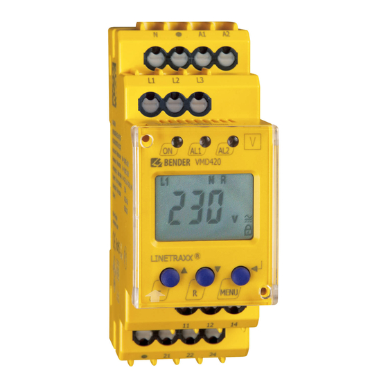
Front Panel Display
1.
LED "ON" (green): Illuminates when
power is applied to the device. Flashes
when the CT connection alarm is active.
2.
LED "AL1" (yellow): Illuminates when
the prealarm is activated. Flashes when
the CT connection alarm is active.
3.
LED "AL2" (yellow): Illuminates when
the main alarm is activated. Flashes
when the CT connection alarm is active.
4.
Backlit LCD display
Dimensions
Dimensions in inches (mm).
K2 STATE
Menu Flow Chart for Common Settings
21-22 CLOSED
Figure 4 through figure 8 on the reverse side of this document contain flow charts for modify-
21-24 OPEN
ing commonly used features and settings in the VMD420's main menu. Not all available fea-
tures are listed in this document. For more information, consult the VMD420 user manual.
21-22 CLOSED
21-24 OPEN
Menu Legend
21-22 OPEN
21-24 CLOSED
DOWN ARROW button
R
21-22 OPEN
21-24 CLOSED
UP ARROW button
T
21-22 CLOSED
21-24 OPEN
MENU / ENTER button
21-22 CLOSED
21-24 OPEN
Installation Bulletin / Reference Guide
1
2
3
4
5
6
7
Figure 2 - VMD420 front display
5.
TEST / UP button: Activates self-test /
scrolls up inside main menu.
6.
RESET / DOWN button: Resets device /
scrolls down inside main menu.
7.
MENU / ENTER button: Activates main
menu / Confirms (momuntary push) or
goes back a step (held > 1.5 s) inside
main menu.
2.78"
(70.5)
1.87"
1.42" (36)
(47.5)
1.22" (31.1)
< 1.5 s
> 1.5 s
Document NAE1038020 • 10.2012 • © Bender Inc. • Page 1/1 • Side 1/2
VMD420
Momuntary button push
Hold button for at least 1.5 s,
then release
Advertisement

Related Manuals for Bender VMD420


Summary of Contents for Bender VMD420
- Page 1 11-14 OPEN 21-24 OPEN Bender Inc. • USA: 800.356.4266 / 610.383.9200 / info@bender.org • Canada: 800.243.2438 / 905.602.9990 / info@bender-ca.com • www.bender.org Document NAE1038020 • 10.2012 • © Bender Inc. • Page 1/1 • Side 1/2...
- Page 2 < 1.5 sec Figure 6 - Latching behavior (fault memory) Changing this setting to “ON” will cause the VMD420 to latch in the event of an alarm, and < 1.5 sec require a manual reset if the alarm clears. Changing this setting to “OFF” will cause the VMD420 To quit to automatically reset if the alarm clears.
Need help?
Do you have a question about the VMD420 and is the answer not in the manual?
Questions and answers