Bender VMD421H Manual
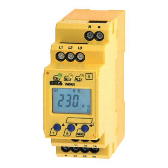
Voltage and frequency monitor for undervoltage, overvoltage, underfrequency and overfrequency monitoring in 3 n ac systems of 70...500 v, software version d239 v2.2x
Hide thumbs
Also See for VMD421H:
- Operating manual (48 pages) ,
- Manual (44 pages) ,
- Quick start manual (8 pages)

Related Manuals for Bender VMD421H


Summary of Contents for Bender VMD421H
- Page 1 Manual VMD421H Voltage and frequency monitor for undervoltage, overvoltage, underfrequency and overfrequency monitoring in 3(N)AC systems of 70...500 V Software version D239 V2.2x VMD421H_D00138_01_M_XXEN/05.2016...
- Page 2 Bender GmbH & Co. KG P.O. Box 1161 • 35301 Gruenberg • Germany Londorfer Strasse 65 • 35305 Gruenberg • Germany Tel.: +49 6401 807-0 • Fax: +49 6401 807-259 E-Mail: info@bender.de • www.bender.de © Bender GmbH & Co. KG All rights reserved.
-
Page 3: Table Of Contents
Table of Contents 1. Important information ..................5 How to use this manual ................. 5 Technical support: service and support ........... 6 1.2.1 First level support ..................... 6 1.2.2 Repair service ..................... 6 1.2.3 Field service ......................7 Training courses ....................8 Delivery conditions .................. - Page 4 5.5.11 Device information query ................45 5.5.12 History memory query ................. 46 Commissioning ....................47 Preset function/ factory setting ............... 48 6. Technical data VMD421H ................51 Data in tabular form ..................51 Standards, approvals and certifications ..........54 Ordering information ................... 55...
-
Page 5: Important Information
1. Important information 1.1 How to use this manual This manual is intended for qualified personnel working in electrical engineering and electronics! Always keep this manual within easy reach for future reference. To make it easier for you to understand and revisit certain sections in this man- ual, we have used symbols to identify important instructions and information. -
Page 6: Technical Support: Service And Support
Important information This manual has been compiled with great care. It might nevertheless contain errors and mistakes. Bender cannot accept any liability for injury to persons or damage to property resulting from errors or mistakes in this manual. 1.2 Technical support: service and support For commissioning and troubleshooting Bender offers you: 1.2.1... -
Page 7: Field Service
Please send the devices for repair to the following address: Bender GmbH, Repair-Service, Londorfer Str. 65, 35305 Gruenberg 1.2.3 Field service On-site service for all Bender products Commissioning, configuring, maintenance, troubleshooting of Bender products Analysis of the electrical installation in the building (power quality test, ... -
Page 8: Training Courses
ZVEI (Zentralverband Elektrotechnik- und Elektronikindustrie e. V.) (German Electrical and Electron- ic Manufacturer's Association) also applies. Sale and delivery conditions can be obtained from Bender in printed or elec- tronic format. 1.5 Inspection, transport and storage Inspect the dispatch and equipment packaging for damage, and compare the contents of the package with the delivery documents. -
Page 9: Warranty And Liability
Important information 1.6 Warranty and liability Warranty and liability claims in the event of injury to persons or damage to property are excluded if they can be attributed to one or more of the follow- ing causes: Improper use of the device. ... -
Page 10: Disposal
13 August 2005 must be taken back by the manufacturer and disposed of properly. For more information on the disposal of Bender devices, refer to our homepage at www.bender-de.com -> Service & support. -
Page 11: Safety Instructions
2. Safety instructions 2.1 General safety instructions Part of the device documentation in addition to this manual is the enclosed "Safety instructions for Bender products". 2.2 Work activities on electrical installations Only qualified personnel are permitted to carry out the work necessary to install, commission and run a device or system. -
Page 12: Intended Use
Safety instructions 2.3 Intended use The voltage monitor VMD421H monitors 3(N)AC systems in the frequency range 15…460 Hz for undervoltage, overvoltage, underfrequency and over- frequency. The devices are designed for the nominal voltage range U 70…500 V. The device is internally supplied by the nominal voltage U to be monitored. -
Page 13: Function
3. Function 3.1 Device features Under and overvoltage monitoring in 3(N) AC systems Preset function: Automatic response value setting for undervoltage and overvoltage, < U and > U as well as for underfrequency and over- frequency < f and > f. Voltage and frequency monitoring with window discriminator func- ... -
Page 14: Fast Commissioning For Un = 400 V, 50 Hz
3. When the conditions 1 and 2 are satisfied, you can connect the voltage monitor to the three-phase system to be monitored according to the wiring diagram (page 23). The following predefined response values will be set automatically: VMD421H Preset Response value Response value operating range <... -
Page 15: Preset Function
+ 1 Hz Response value underfrequ. ( < f) at 16.7 Hz, 50 Hz, 60 Hz: f - 1 Hz Response value underfrequency ( < f) at 400 Hz: f - 1 Hz Preset VMD421H Preset Response Response Measuring principle... -
Page 16: Automatic Self Test
While the test button T is pressed and held down, all device-related display elements appear on the display. 3.7 Functional fault If an internal functional fault occurs, all three LEDs flash. An error code will ap- pear on the display (E01…E32). In such a case please contact the Bender Ser- vice. VMD421H_D00138_01_M_XXEN/05.2016... -
Page 17: Fault Memory
Function 3.8 Fault memory The fault memory can be activated, deactivated or can be set to continuous mode (con). If the fault memory is set to "con" mode, the stored alarm para- meters remain stored also in the event of failure of the nominal voltage (U ) and also when the energy backup discharging time has elapsed. -
Page 18: Password Protection (On, Off)
With the password protection activated (on), settings are only possible after entering the correct password (0…999). If you cannot operate your device be- cause you cannot remember your password, please contact info@bender-service.com. 3.12 Factory setting FAC After activating the factory setting, all settings previously changed are reset to delivery status. -
Page 19: Starting A Device Using A Simulated Alarm S.al
Function 3.15 Starting a device using a simulated alarm S.AL If the menu item S.AL has been activated in the out menu, K1 resp. K2 switches back to the alarm state once the nominal voltage is applied. This alarm state is maintained for the set duration t + t . - Page 20 Function VMD421H_D00138_01_M_XXEN/05.2016...
-
Page 21: Installation And Connection
4. Installation and connection Only qualified personnel are permitted to carry out the work necessary to install, commission and run a device or system. Risk of electrocution due to electric shock! Touching live parts of the system carries the risk of: An electric shock ... - Page 22 Installation and connection General dimension diagram and drawing for screw fixing Mount the device vertically, to allow sufficient air flow through the ventilation slots at top and bottom! The front plate cover is easy to open at the lower part identified by an arrow. 1.
- Page 23 Installation and connection 2. Wiring Connect the device according the wiring diagram. Terminal Connections L1, L2, L3, Connection to the system being monitored 11, 12, 14 Alarm relay K1 21, 22, 24 alarm relay K2 VMD421H_D00138_01_M_XXEN/05.2016...
- Page 24 Installation and connection VMD421H_D00138_01_M_XXEN/05.2016...
-
Page 25: Operation And Setting
5. Operation and setting 5.1 Display elements in use The meaning of the display elements in use is listed in detail in the table below. Display elements in use Element Function L1…L3N Conductor L1…L3 (phase), neutral conductor Asy, % Asymmetry as % <... -
Page 26: Function Of The Operating Elements
Operation and setting 5.2 Function of the operating elements Elemen Device front Function Power On LED, green Menu item LEd deactivated: AL1, LED Alarm 1 lights (yellow): Response value > U exceeded, LED Alarm 2 lights (yellow): Response value < U reached AL1 AL2 Menu item LEd deactivated:... -
Page 27: Menu Structure
Operation and setting MENU key (> 1.5 s): Starting the menu mode; MENU, Enter key (< 1.5 s): Confirm menu item, submenu item and value. Enter key (> 1.5 s): Back to the next higher menu level. For further information about the menu item LEd refer to page 18. - Page 28 Operation and setting Menu Activati Menu Adjustable parameter menu item Fault memory (on, con, off ) (output con- Operating mode K1 (n.o.) trol) Operating mode K2 (n.c.) LEDs signal relay in alarm state 1 Err Device error at K1 r1 < U OFF Undervoltage K1 r1 >...
- Page 29 Operation and setting Menu Activati Menu Adjustable parameter menu item L1L2L3 - Measuring principle: phase -to-phase voltage (device con- 3 Ph, trol) phase-to-neutral voltage 3n Parameter setting via pass- word Re-establish factory set- tings Manual preset Function blocked Query hardware / software version History memory for the first alarm value, erasable...
-
Page 30: Display In Standard Mode
Operation and setting 5.4 Display in standard mode By default, the display shows the phase-to-phase voltage between L1 and L2. By pressing the Up or Down key, details about asymmetry, system frequency and phase sequence are displayed, for example. In order to change the de- fault display, confirm your choice with Enter. -
Page 31: Display In Menu Mode
Operation and setting 5.5 Display in menu mode 5.5.1 Parameter query and setting: overview Adjustable parameter Menu item Response value query and setting: – Undervoltage: < U (AL2) – Overvoltage: > U (AL1) – Hysteresis of the voltage response values: Hys U –... - Page 32 Operation and setting Menu structure VMD421H_D00138_01_M_XXEN/05.2016...
- Page 33 Operation and setting Parameter settings An example is given below on how to change the alarm response value for overvoltage > U. Proceed as follows: 1. Press the MENU/Enter key for more than 1.5 seconds. The flashing short symbol AL appears on the display. 2.
-
Page 34: Setting The Response Values For Under And Overvoltage
Operation and setting 5.5.2 Setting the response values for under and overvoltage: - Value of the undervoltage (< U) - Value of the overvoltage (> U) - Hysteresis (Hys) of the response values < U and > U - Asymmetry (Asy) of the phases - Phase sequence (PHS) anticlockwise (L) or clockwise (R) , in the example below from R to L Setting the undervoltage response value <... - Page 35 Operation and setting Setting the hysteresis of the voltage response values Setting the asymmetry response value Setting the phase sequence response value VMD421H_D00138_01_M_XXEN/05.2016...
-
Page 36: Setting The Response Values For Underfrequency, Overfrequency
Operation and setting 5.5.3 Setting the response values for underfrequency, overfrequency and hysteresis Setting the underfrequency response value < Hz Setting the overfrequency response value > Hz VMD421H_D00138_01_M_XXEN/05.2016... -
Page 37: Setting Fault Memory/Operating Principle Of The Alarm Relays
Operation and setting Setting the hysteresis of the frequency response values 5.5.4 Setting fault memory/operating principle of the alarm relays Deactivating the fault memory Setting the alarm relay K1 to N/C operation (n.c.) VMD421H_D00138_01_M_XXEN/05.2016... - Page 38 Operation and setting Setting the alarm relay K2 to N/O operation (n.o.) LEDs AL1/AL2 are intended to indicate the alarm state of K1/K2 VMD421H_D00138_01_M_XXEN/05.2016...
-
Page 39: Assigning Alarm Categories To The Alarm Relays
Operation and setting 5.5.5 Assigning alarm categories to the alarm relays Undervoltage, overvoltage, underfrequency, overfrequency, asymmetry, pha- se sequence and device-related error messages of the voltage monitor can be assigned to the alarm relays K1 (r1, 1) and K2 (r2, 2). K1 is set at the factory to signal an alarm in the event of overvoltage, and K2 is set to signal an alarm in the event of undervoltage. - Page 40 Operation and setting Alarm relay K1: Deactivating the category overvoltage Alarm relay K1: Deactivating the category asymmetry alarm When an alarm relay (K1/K2) has been deactivated via the menu, an alarm will not be signalled by the respective changeover contact! An alarm will only be indicated by the respective alarm LED (AL1/AL2)! CAUTION This only applies to the out menu setting LEd = off!
-
Page 41: Setting The Time Delay
Operation and setting Alarm relay K1: Deactivating the category phase sequence alarm 5.5.6 Setting the time delay The following delays can be set: Response delay t (0…300 s) for K1, and t (0…300 s) for K2 Starting delay t (0…300 s) when the device is being started. ... -
Page 42: Selecting The Measuring Method
Operation and setting Setting the starting delay t 5.5.7 Selecting the measuring method Use this menu item to select between phase to N (3n) or phase-to-phase (3Ph) measuring. If the device has been connected to the neutral conductor and the phase conductors you can use either measuring method. -
Page 43: Factory Setting And Password Protection
Operation and setting 5.5.8 Factory setting and password protection Use this menu to activate the password protection, to change the password or to deactivate the password protection. In addition, you can reset the device to its factory settings. a) Activating the password protection b) Changing the password VMD421H_D00138_01_M_XXEN/05.2016... -
Page 44: Re-Establishing The Factory Settings
Operation and setting c) Deactivating the password protection 5.5.9 Re-establishing the factory settings VMD421H_D00138_01_M_XXEN/05.2016... -
Page 45: Manual Activation Of The Preset Function
Operation and setting 5.5.10 Manual activation of the preset function During the operating process, the measuring principle is being queried. You have two measuring principles to choose from, the three-phase-N-measure- ment (3n) or the three-phase measurement (3Ph). In the example below, the three-phase measurement has been selected. -
Page 46: History Memory Query
Operation and setting 5.5.12 History memory query The history memory can be selected via the menu HiS. Use the Up and Down keys to view the next display. If Clr is flashing, the history memory can be cle- ared by pressing the Enter key. VMD421H_D00138_01_M_XXEN/05.2016... -
Page 47: Commissioning
Operation and setting 5.6 Commissioning Prior to commissioning, check proper connection of the voltage monitor. After connecting a brand-new VMD421H… to a standard system of Un = 400 V 50 Hz, the response values are automatically set by the internal preset function:... -
Page 48: Preset Function/ Factory Setting
Operation and setting 5.7 Preset function/ factory setting Hysteresis U: Underfrequency < Hz Overfrequency > Hz Hysteresis frequency (Hys Hz): 0.2 Hz Fault memory M: Operating principle K1 (> U, Asy): N/O operation (n.o.) Operating principle K2 (< U, Asy): N/C operation (n.c.) AL1/AL2 indicate the alarm state of K1/K2 (LEd):... - Page 49 Operation and setting Hysteresis U: Underfrequency < Hz Overfrequency > Hz Hysteresis frequency (Hys Hz): 0.2 Hz Fault memory M: Operating principle K1 (> U, Asy): N/O operation (n.o.) Operating principle K2 (< U, Asy): N/C operation (n.c.) AL1/AL2 indicate the alarm state of K1/K2 (LEd): Alarm to K1/K2 (S.AL) when the device is started:...
- Page 50 Operation and setting VMD421H_D00138_01_M_XXEN/05.2016...
-
Page 51: Technical Data Vmd421H
6. Technical data VMD421H 6.1 Data in tabular form ( )* = factory setting Insulation coordination acc. to IEC 60664-1/IEC 60664-3 Rated insulation voltage ............................400 V Rated impulse voltage/pollution degree......................4 kV / III Protective separation (reinforced insulation) between......(N, L1, L2, L3) - (11, 12, 14) - (21, 22, 24) Voltage test acc. - Page 52 Technical data VMD421H Hysteresis U ............................1…40 % (5 %)* Asymmetry ............................5…30 % (30 %)* Phase failure........................by setting of the asymmetry Phase sequence ....................clockwise/ anticlockwise rotation (off)* Relative percentage error, voltage at 50 Hz / 60 Hz ................ ±1.5 %, ±2 digits Relative percentage error in the voltage range of 15 Hz…460 Hz...........
- Page 53 Technical data VMD421H History memory (HiS) for the first alarm value..............data record measured values Password ............................Off / 0…999 (OFF)* Fault memory (M) alarm relay ...................... on / off / con (on)* Switching elements Number of changeover contacts ....................... 2 x 1 (K1, K2) Operating principle..................
-
Page 54: Standards, Approvals And Certifications
Technical data VMD421H Connection ........................push-wire terminals Connection properties: Rigid .......................... 0.2…2.5 mm ( AWG 24…14) Flexible without ferrules ..................0.75…2.5 mm ( AWG 19…14) Flexible with ferrules....................0.2…1.5 mm ( AWG 24…16) Stripping length ..............................10 mm Opening force................................50 N Test opening, diameter............................ -
Page 55: Ordering Information
Technical data VMD421H 6.3 Ordering information Nominal system voltage U Device type Art. No. B 7301 0007 3(N)AC 70…500 V/ 288 V (Push-wire ter- VMD421H-D-3 15…460 Hz minals) 3(N)AC 70…500 V/ 288 V B 9301 0007 VMD421H-D-3 15…460 Hz *Absolute values of the voltage range... - Page 56 Technical data VMD421H VMD421H_D00138_01_M_XXEN/05.2016...
- Page 57 INDEX Adjustable parameters, list 27 How to use this manual 5 Automatic self test 16 Indication of the alarm state of K1/K2 18 currently measured values Installation and connection 21 - asymmetry 30 Intended use 12 - phase sequence 30 - phase-to-phase voltage 30 K1: assignment alarm category 28 - rated frequency 30...
- Page 58 Ordering information 55 Service 6 Simulated alarm 19 Parameter query and setting, overview 31 Starting a device using a simulated alarm Parameter setting S.AL 19 - Activating or deactivating the pass- Starting delay t 17 word protection 43 Starting the menu mode 27 - Assigning alarm categories to the Support 6 alarm relays 39...
- Page 60 Bender GmbH & Co. KG P.O. Box 1161 • 35301 Gruenberg • Germany Londorfer Strasse 65 • 35305 Gruenberg • Germany Tel.: +49 6401 807-0 • Fax: +49 6401 807-259 E-Mail: info@bender.de • www.bender.de Group Photos: Bender archives...
Need help?
Do you have a question about the VMD421H and is the answer not in the manual?
Questions and answers