
Related Manuals for Bender rcm420


Summary of Contents for Bender rcm420
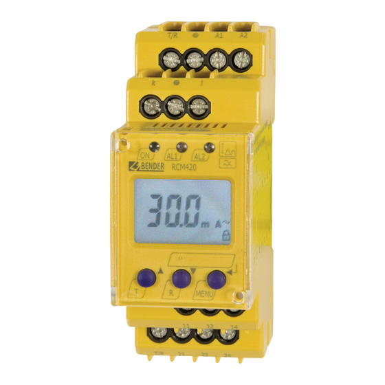
- Page 1 Operating Manual RCM420 Residual current monitor for AC current monitoring in TN and TT systems Software version: D240 V1.2x TGH1410en/03.2012...
- Page 2 Bender GmbH & Co. KG Londorfer Str. 65 • 35305 Grünberg • Germany Postfach 1161 • 35301 Grünberg • Germany Tel.: +49 6401 807-0 Fax: +49 6401 807-259 E-Mail: info@bender-de.com Web: http://www.bender-de.com © Bender GmbH & Co. KG All rights reserved.
-
Page 3: Table Of Contents
Table of Contents 1. Effective use of this manual ................5 Notes for the user ..................... 5 Intended use ...................... 5 Information about factory setting ............. 6 2. Safety information ................... 7 Safety instructions ................... 7 Work activities on electrical installations ..........7 3. - Page 4 Table of Contents 3.2.18 Fault memory ....................12 4. Installation and connection ................. 13 5. Operation and setting .................. 17 Display elements ................... 17 Function of the operating elements ............18 Menu structure ....................19 Display in standard mode ................21 Display in menu mode ................
-
Page 5: Effective Use Of This Manual
Info symbol. 1.2 Intended use The AC and pulsed DC sensitive residual current monitor RCM420 (Type A) from Bender is designed for fault and residual current monitoring in earthed power supply systems (TN/TT systems) where an alarm is to be activated in the event of a fault, but disconnection must be prevented. -
Page 6: Information About Factory Setting
Effective use of this manual 1.3 Information about factory setting Page 34 provides a summary of all factory settings. If you want to reset the residual current monitor to factory settings, refer to page 32. TGH1410en/03.2012... -
Page 7: Safety Information
2. Safety information 2.1 Safety instructions In addition to this data sheet, the documentation of the device includes a sheet entitled "Important safety instructions for BENDER products“. 2.2 Work activities on electrical installations All work activities necessary for installation, commissioning or work ... - Page 8 Safety information TGH1410en/03.2012...
-
Page 9: Function
3. Function 3.1 Device features AC and pulsed DC sensitive residual current monitor Type A according to IEC 62020 Adjustable switching hysteresis r.m.s. value measurement Starting delay, response delay and delay on release Measured value display via multi-functional LC display ... -
Page 10: Connection Monitoring
Function tion can be tested using the test button T. The parameterization of the device can be carried out via the LC display and the function keys integrated in the front plate and can be password-protected. 3.2.1 Connection monitoring The CT connections are continuously monitored. In the event of a fault, the alarm relays K1 / K2 switch without delay, the alarm LEDs AL1 / AL2 / ON flash (Error Code E.01). -
Page 11: Functional Faults
3.2.6 Functional faults If an internal functional fault occurs, all three LEDs flash. An error code will appear on the display (E01...E32). In such a case please contact the Bender Service. 3.2.7 Set the number of reload cycles... -
Page 12: Delay On Release Toff
Function 3.2.12 Delay on release t When no alarm exists after deactivating the fault memory, the alarm LEDs go out and the alarm relays switch back to their initial position. After activating the delay on release (0...300 s), the alarm state is continuously maintained for the selected period. -
Page 13: Installation And Connection
4. Installation and connection Ensure safe isolation from supply in the installation area. Ob- serve the installation rules for live working. Dimension diagram, drawing for screw mounting, push-wire ter- minal connection Zubehör/ Accessory 36 mm The front plate cover is easy to open at the lower part marked by an arrow. TGH1410en/03.2012... - Page 14 Installation and connection 1. DIN rail mounting: Snap the rear mounting clip of the device into place in such a way that a safe and tight fit is ensured. Screw fixing: Use a tool to move the rear mounting clips (a second mounting clip required, see ordering information) to a position that it projects beyond the enclosure.
- Page 15 = 100 (500 A / 5 A). That means, when the lowest value of 10 mA is set at the RCM420, a current of 1 A can only just be detected on the primary side of the transformer on the load side. In order to reduce the value that can be de- tected to 100 mA, 10 turns of the supply cable has to be routed through the transformer on the RCM side.
- Page 16 Installation and connection TGH1410en/03.2012...
-
Page 17: Operation And Setting
5. Operation and setting 5.1 Display elements A detailed description of the meaning of the display elements is given in the table below. Ele- Display elements Function ment Reload function with memory = off (L = I.) Transformation ratio factor for a second external measuring current transformer. -
Page 18: Function Of The Operating Elements
Operation and setting 5.2 Function of the operating elements Ele- Device front Function ment lights continuously: Power On LED green flashes: System fault or connection moni- toring fault AL1, LED Alarm 1 lights (yellow): Response value 1 reached Δn1 LED Alarm 2 lights (yellow): Response value 2 reached Δn2 13 mA... -
Page 19: Menu Structure
Operation and setting 5.3 Menu structure All adjustable parameters are listed in the columns "menu item" and "adjusta- ble parameters". A display-like representation is used to illustrate the param- eters in the column menu item. Different alarm categories can be assigned to the alarm relays K1, K2 via the submenus r1, r2. - Page 20 Operation and setting Menu Activati Menu Adjustable parameter Menu item t on 1 Response delay K1 t on 2 Response delay K2 (timing check) Starting delay t off Delay on release K1/K2 Selectable parameters: I 12 High, window function, low Transformation ratio factor for a second external meas- uring current transformer.
-
Page 21: Display In Standard Mode
Operation and setting 5.4 Display in standard mode By default, the currently measured residual current is displayed. The current response values I1 (prewarning) and I2 (alarm) can be displayed using the Up and Down key. Press the Enter key to return to the measured value. In the standard mode, the currently set response values I 1 and I 2 can be displayed using the Up and Down keys. -
Page 22: Display In Menu Mode
Operation and setting 5.5 Display in menu mode 5.5.1 Parameter query and setting: Overview Menu Adjustable parameter item Response values query and setting: – Residual current I2 (I ) (AL2) Δn2 – Residual current I1 (I ) (AL1) Δn1 – Hysteresis of the response values: % Hys Configuration of the fault memory and the alarm relays: –... - Page 23 Operation and setting Menu structure t >1,5 s t > 1,5 s t < 1,5 s t < 1,5 s t > 1,5 s Parameter settings The following description is based on the fact that the device is in the stand- TGH1410en/03.2012...
-
Page 24: Changeover From Overcurrent To Undercurrent Mode Or To Window Mode
Operation and setting ard mode and that the measured value of the residual current is being indicat- ed, refer to page 21. An example is given here on how to change the alarm response value I1 (I Δn1 It is presumed that the option overcurrent (HI) has been selected in the SEt/I 12 menu (factory setting). -
Page 25: Response Value Setting For Overcurrent
Operation and setting 5.5.3 Response value setting for overcurrent: - Response value I2 (overcurrent I Δn2 - Response value I1 (overcurrent I Δn1 - Hysteresis (Hys) of the response values I Δn1 Δn2 Increasing the response value I2 (alarm overcurrent) Increasing the response value I1 (prewarning overcurrent). -
Page 26: Setting The Fault Memory And Alarm Relay Operating Mode
Operation and setting 5.5.4 Setting the fault memory and alarm relay operating mode Setting the fault memory to con mode Setting the alarm relay K1 to N/O operation (n.o.) Setting the number of reload cycles >1,5 s TGH1410en/03.2012... -
Page 27: Assigning Alarm Categories To The Alarm Relays
Operation and setting 5.5.5 Assigning alarm categories to the alarm relays Overcurrent, undercurrent and device-related errors of the residual current monitor can be assigned to the alarm relays K1 (r1, 1) and K2 (r2, 2). By default, the alarm relays K1 and K2 signal prewarning and alarm in case of overcurrent and device-related errors. - Page 28 Operation and setting Alarm relay K1: Activating the category response value I2 >1,5 s Alarm relay K1: Deactivating the category "Alarm by device test" >1,5 s When an alarm relay (K1/K2) has been deactivated in the menu, an alarm will not be signalled by the respective changeover contact! An alarm will only be indicated by the respective alarm LED (AL1/AL2)! TGH1410en/03.2012...
-
Page 29: Set The Time Delays
Operation and setting 5.5.6 Set the time delays The following delays can be set: Response delay t (0...10 s) for K1, and t (0...10 s) for K2 Starting delay t (0...10 s) when the device is being started Common delay on release t (0...99 s) for K1, K2. -
Page 30: Changing From Overcurrent Operation To Window Operation
Operation and setting 5.5.7 Changing from overcurrent operation to window operation Use this menu item to set whether the response values of the device apply to overcurrent (HI) or undercurrent operation (Lo). In addition, window opera- tion (In) can be selected. >1,5 s 5.5.8 Setting the correction factor for an additional cascaded cur-... -
Page 31: Factory Setting And Password Protection
Operation and setting 5.5.9 Factory setting and password protection Use this menu to activate the password protection, to change the password or to deactivate the password protection. In addition, you can reset the device to its factory settings. a) Activating the password protection >1,5 s b) Changing the password >1,5 s... -
Page 32: Re-Establishing The Factory Settings
Operation and setting c) Deactivating the password protection >1,5 s 5.5.10 Re-establishing the factory settings ..TGH1410en/03.2012... -
Page 33: Device Information Query
Operation and setting 5.5.11 Device information query This function is used to query the software (1.xx) versions. After activating this function, data will be displayed as a scrolling text. Once one pass is completed you can select individual data sections using the Up/Down keys.. -
Page 34: Commissioning
Operation and setting 5.6 Commissioning Prior to commissioning, check proper connection of the residual current mon- itor. Factory setting Response value overcurrent I1 (prewarning) 15 mA (50 % of I2) Response value overcurrent I2 (alarm) 30 mA Hysteresis: 15 % Fault memory M: activated (on) Operating mode K1/K2... -
Page 35: Technical Data
......................(A1, A2) - (k/l, T/R) - (11, 12, 14) - (21, 22, 24) Voltage test according to IEC 61010-1 ....................... 2.21 kV Supply voltage RCM420-D-1: Supply voltage U ....................... AC 16...72 V / DC 9.6...94 V Frequency range U ............................ - Page 36 ........................0...10 m Shielded cable ≥ 0.75 mm ..........................0...40 m Recommended cable (shielded, shield on one side connected to terminal l of the RCM420, not connected to earth) ......................................J-Y(St)Y min. 2 x 0.8 Connection ..............................screw terminals Displays, memory Display range, measured value ........................
- Page 37 Technical data Utilization category...............AC-13..AC-14..DC-12..DC-12..DC-12 Rated operational voltage .............230 V ...230 V .....24 V ..110 V ..220 V Rated operational current............5 A....3 A....1 A... 0.2 A..0.1 A Minimum contact load......................1 mA at AC / DC ≥ 10 V Environment/EMC EMC ..................................
-
Page 38: Ordering Information
DIN rail mounting acc. to..........................IEC 60715 Screw mounting........................2 x M4 with mounting clip Weight ................................≤ 150 g ( )* = factory setting 6.2 Ordering information RCM420-D...-1 RCM420-D...-2 Response range I Δ 10 mA...10 A 10 mA...10 A 42...2000 Hz... - Page 39 B 9808 0603 WS80x120 80 x 120 B 9808 0606 RCM420 accessories Mounting clip for screw fixing (1 piece per device) ................. B 9806 0008 Measuring current transformers accessories Snap-on mounting for DIN rail: W20... /W35..................B 9808 0501 Snap-on mounting for DIN rail: W60 ......................B 9808 0502...
-
Page 40: Error Codes
Appropriate action when error codes > 02 occur: Carry out a reset. Reset the device to factory E..setting. After eliminating the fault, the error code will be automatically deleted. If the fault continues to exist, please contact the Bender Service. TGH1410en/03.2012... -
Page 41: Index
INDEX Adjustable parameters, list 19 K1/K2: assignment alarm category 19 Automatic self test 10 LED Alarm 1 lights 18 Connection of an additional cascaded meas- LED Alarm 2 lights 18 uring current transformer 15 Continuous mode (con), fault memory 12 Manual self test 10 Manual, target group 5 Delay on release toff 12... - Page 42 Starting the menu mode 18 Parameter query and setting, overview 22 Parameter setting Technical data 35 - Activating or deactivating the pass- Test button 18 word protection 31 - Assigning alarm categories to the alarm relays 27 Wiring diagram 14 - Changing from overcurrent opera- Wondow mode 30 tion to window operation 30...
- Page 44 Bender GmbH & Co. KG Londorfer Str. 65 • 35305 Grünberg • Germany Postfach 1161 • 35301 Grünberg • Germany Tel.: +49 6401 807-0 Fax: +49 6401 807-259 E-Mail: info@bender-de.com Web: http://www.bender-de.com...
Need help?
Do you have a question about the rcm420 and is the answer not in the manual?
Questions and answers