
Related Manuals for Bender COMTRAXX CP700


Summary of Contents for Bender COMTRAXX CP700
- Page 1 Manual COMTRAXX® CP700 Condition Monitor for the connection of Bender BMS devices and universal measuring devices to TCP/IP networks Software version: V1.8 CP700_D00005_02_M_XXEN/06.2014...
- Page 2 Bender GmbH & Co. KG © Bender GmbH & Co. KG P.O.Box 1161 • 35301 Grünberg • Germany All rights reserved. Londorfer Straße 65 • 35305 Grünberg • Germany Reprinting only with permission Tel.: +49 6401 807-0 • Fax: +49 6401 807-259 of the publisher.
-
Page 3: Table Of Contents
Table of Contents 1. Making effective use of this document ............... 9 How to use this manual ......................9 Quick start ........................... 9 2. Safety instructions ....................11 Work activities on electrical installations ..............11 Intended use ........................... 11 Address setting and termination ..................12 Delivery conditions, guarantee, warranty and liability ........... - Page 4 5.3.4 "Bus overview" menu ......................32 5.3.5 Displaying the device info for CP700 ................33 5.3.6 Using the functions for Bender PEM… universal measuring devices ....33 6. Web user interface of the CP700 ............... 35 Menu structure of the web user interface ..............35 Browser configuration ......................
- Page 5 Table of Contents 6.6.9.3 Exporting the history memory .................. 52 6.6.9.4 Delete the history memory ..................52 6.6.9.5 Displaying the history memory of BMS devices ..........52 6.6.10 Data logger ..........................53 6.6.10.1 Data logger setting ......................53 6.6.10.2 Displaying the data logger ..................53 6.6.10.3 Evaluating the data logger ..................
- Page 6 Table of Contents 6.12.7.2 Acquiring licences for additional software options and loading the licence file ............................91 6.12.7.3 Activate acquired software options ................. 92 6.12.8 Modbus register ........................93 6.12.8.1 Modbus representation of device information ............ 93 6.12.8.2 Modbus representation of a BMS channel ............94 6.12.9 Modbus control commands for BMS devices ..............
- Page 7 Table of Contents 6.15.3 Changing a virtual device ....................118 6.15.4 Setting the channels of a virtual device ..............119 7. Data access using the Modbus/TCP protocol ..........121 Exception code ........................121 Modbus requests ........................ 121 Modbus responses ......................122 Structure of an exception code ..................
- Page 8 Table of Contents 9.2.2 Acknowledging alarm messages for events ............. 143 9.2.3 Acknowledging alarm messages for events ............. 143 Displaying a PEM…'s voltages/currents ..............144 Displaying the phasor diagram of a PEM… .............. 145 Displaying harmonics by means of PEM… ............... 146 Waveform recorder of a PEM575 universal measuring device ......
-
Page 9: Making Effective Use Of This Document
1. Making effective use of this document 1.1 How to use this manual This operating manual will concern qualified experts in electrical engineering and communica- tion technology! To make it easier for you to understand and revisit certain sections of text and instructions in the manual, we have used symbols to identify important instructions and information. - Page 10 Making effective use of this document CP700_D00005_02_M_XXEN/06.2014...
-
Page 11: Safety Instructions
The Condition Monitor CP700 connects the following devices to Ethernet TCP/IP networks: Devices on the Bender internal serial BMS bus Bender universal measuring devices PEM… to Modbus/RTU or Modbus/TCP. The CP700 converts alarms, measured values and statuses into Modbus/TCP protocols and HTTP. -
Page 12: Address Setting And Termination
The conditions of sale and delivery set out by Bender apply. Conditions of sale and delivery can be obtained from Bender in printed or electronic format. The five year guarantee "5forU" does not include parts subject to wear, such as the touch screen and the battery. -
Page 13: Product Description
Selective e-mail notification to various user groups in the event of alarms Support of professional visualisation programs Observing and analysing of compatible Bender products (universal measuring devices, RCMS, Isometer, EDS systems) Parameter setting for devices, storing, documentation and restoring of parameters in a clear ... -
Page 14: Description Of Function
The CP700 can usually be integrated into existing LAN structures, but can also be operated on a sin- gle PC via Ethernet/TCP/IP. The CP700 can also be used as master for Bender BMS devices and/or uni- versal measuring devices without being connected to a PC. -
Page 15: Functions Available Via Touch Screen
These commands can be copied to the clipboard of the PC and then included in the programming for external application. A graphical representation for the CP700 data logger and compatible Bender devices is avail- able. The time axis can be varied to view different periods. -
Page 16: Software Products Used
Product description System visualisation: Displaying several gateways (COM460IP, CP700) on one website. Display- ing common alarms of the devices. Clicking on a device being displayed will open its web user interface. Displaying the CP700 operating manual 3.5 Software products used MIT license (http://opensource.org/licenses/mit-license.php) ... -
Page 17: Installation, Connection And Commissioning
You will find more detailed information on the BMS topic, in particular about the wiring of bus devices, in the separate document "BMS bus". You can download the document from the download area of the website www.bender.de. 3. Does the computer network comprise a DHCP server? Otherwise, the network data such as the IP address and netmask allocated by the person responsible for the electrical installation have to be set manually. -
Page 18: Type Of Installation
Installation, connection and commissioning The device must be installed on a flat surface. While tightening the screws, irregularities may damage the display. The ventilation holes must not be covered. When installing the device, the permissible mounting positions are to be observed. ... - Page 19 Installation, connection and commissioning 3. Fix the mounting brackets to the wall resp. to the sheet metal of the switchboard cabinet by tightening the screws using a large flat-tip screwdriver. A tightening torque of approx. 0.5 Nm is recommended. CP700_D00005_02_M_XXEN/06.2014...
-
Page 20: Connection Of The Device
Modbus/RTU interface. (cable included in the scope of delivery) Switch for terminating resistor/bus bias voltage for Modbus/RTU interface. BMS bus (Bender measuring device interface, cable included in the scope of delivery) Switch for BMS bus termination/bus bias voltage. USB interface, is not used Connection to the supply voltage, "see chapter "DC 24 V power supply"... -
Page 21: Dc 24 V Power Supply
(10 A, fast-acting), so that in case of overload (replacement of the fuse required) or wrong connection of the supply voltage the device will not be damaged. If the fuse is damaged due to a fault, the device has to be returned to Bender for repair. Description... -
Page 22: Bms Bus, Modbus/Rtu
Installation, connection and commissioning An earthing connection (1) is located at the rear of the CP700 for connection to a central earthing point in the switchboard cabinet or the system where the device is to be installed. The largest possi- ble wire cross section (minimum 2.5 mm²) should be used. -
Page 23: Commissioning
Installation, connection and commissioning 4.4 Commissioning 1. Switch the supply voltage on. - The "Settings" > "Interface" menu appears on the touch screen (for details and factory settings refer to page 29). Click on "Login" enter the settings. 2. Set the IP address. If the connected computer network contains a DHCP server, activate the "DHCP"... - Page 24 Installation, connection and commissioning CP700_D00005_02_M_XXEN/06.2014...
-
Page 25: Display And Operating Elements
5. Display and operating elements 5.1 Operating elements at the rear of the device LED "Run" LED "Link" LED "CF" LED "Power". "Reset" button, operation is not required. CP700 starts as soon as supply voltage is applied. When the "Reset" button is pressed, a hardware reset will be initiated. The device restarts (cold start). -
Page 26: Status Leds
Display and operating elements 5.1.1 Status LEDs For the status LEDs (Power, CF, Link, Run), the following time frame is being used: Box width: 250 ms Interval: 500 ms; Hence, 2 boxes correspond to one interval Color Status Meaning LED indicator Power Green Supply voltage OK... -
Page 27: Touchscreen
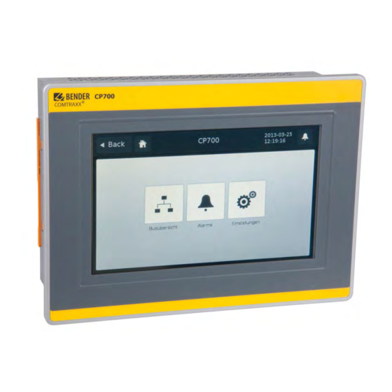
Display and operating elements 5.2 Touchscreen Do not apply excessive force to the screen. Do not use a ballpoint pen, a pencil or other sharp objects to operate the touch screen. This may damage or destroy the touch screen. CAUTION The integrated 7 inch touch screen is used at the same time for indication and operation. -
Page 28: Operation Via Touch Screen
Display and operating elements 5.3 Operation via touch screen After the initial power-up, the CP700 enters the "Settings" > "Interface" menu. By tapping the " " button you will access the main menu. If no entry has been made via the touch screen for several minutes and the touch screen has switched to standby mode, the CP700 will automatically switch to the main menu. -
Page 29: Settings" Menu
Display and operating elements 5.3.2 "Settings" menu Select: Interface Interface parameter setting Language Selection of the operation language for the CP700 5.3.2.1 "Interface" menu Display settings The existing settings will be displayed. If you have not logged in, you cannot change the settings. Therefore the buttons for the setting val- ues are not active (greyed out). - Page 30 Display and operating elements Changing settings The settings can only be changed in the "Logged in" mode. Tap on the "Login" button. A password can be set in the "Bus overview > "Settings" > "Password" menu via the web user inter- face.
-
Page 31: Language" Menu
Display and operating elements Parameter settings and factory settings Factory setting Description 192.168.0.254 Set the IP address of CP700 255.255.0.0 Set the subnet mask of CP700 Standard 192.168.0.1 Set the IP address of the gateway gateway Set the BMS address of CP700: 1…99 (internal BMS bus) Modbus/RTU 9600 Bd, even Modbus/RTU: Select baudrate and parity... -
Page 32: Alarms" Menu
Display and operating elements 5.3.3 "Alarms" menu Indication of alarm messages. Tap on "i" for a help text about this alarm. 5.3.4 "Bus overview" menu The bus overview lists all devices connected to the CP700 as well as all virtual devices. Here, it does not make a difference whether these devices are connected via BMS bus, Modbus/TCP or Modbus/RTU. -
Page 33: Displaying The Device Info For Cp700
Move the presently displayed content upwards to display the rest of the information. 5.3.6 Using the functions for Bender PEM… universal measuring devices Select "Bus overview" > "PEM575 " > "Device info". For a description of these functions refer to chapter "Monitor for Power quality"... - Page 34 Display and operating elements CP700_D00005_02_M_XXEN/06.2014...
-
Page 35: Web User Interface Of The Cp700
6. Web user interface of the CP700 6.1 Menu structure of the web user interface The table below provides an overview of the menus. The menus are easy to use by means of a brows- er. The listing is arranged according to the menu-bar shown below. Menu bar Submenu: Description... - Page 36 Modbus register presentation of the connected BMS devices and PEM... Bender universal measuring devices Modbus control commands Commands can be sent to BMS devices and Bender PEM... universal measuring devices from an external application (e.g. visualisation software). The "Mod- bus control commands" menu provides Modbus control commands for selected BMS commands.
-
Page 37: Browser Configuration
Web user interface of the CP700 6.2 Browser configuration © The latest version of the Windows Internet Explorer is recommended. In order to fully benefit from all functions of the web user interface Silverlight has to be installed on the computer being used and Java Script has to be activated too. In addition, the pop-up blocker has to be deactivated so that all functions are available to you. -
Page 38: Start Page And Operating Language
Web user interface of the CP700 6.4 Start page and operating language 6.4.1 Opening the start page 1. Open an Internet browser. 2. Enter the IP address of the CP700 into the address line (Example: http://162.18.22.18/). The start screen will appear: 6.4.2 Changing the language If a German Windows operating system is installed on the PC, the web user interface will start up in... -
Page 39: Menu Bar
Web user interface of the CP700 6.5 Menu bar The user interface can largely be controlled per mouse click. Menus and functions. Example: Start = select the menu language. Input field for entering the password to log in. The edit filed won't appear unless a "Login"... -
Page 40: Bus Overview And Device Information
Web user interface of the CP700 6.6 Bus overview and device information 6.6.1 Creating a password protection for CP700 Risk of damage to equipment due to unauthorized access The password protection for the CP700 protects against unauthorised access to a limited extent only. Attackers from the Internet may still be able to read data DANGER and to change settings. - Page 41 Web user interface of the CP700 Example: The parameterisation function of the CP700 is to be protected by a new password. According to the table above, a login password has to be assigned. The password protection must also be activated! 1.
-
Page 42: Buttons For The List Of Bus Devices
Web user interface of the CP700 6.6.2 Buttons for the list of bus devices CP700 on the internal BMS bus Button to open or close the list of bus devices and the device menu. Instead of using the triangular buttons it is also possible to double-click or click the button of the bus device resp. -
Page 43: Cp700 On The Internal Bms Bus
Web user interface of the CP700 6.6.3 CP700 on the internal BMS bus The device is operated on the internal bus. Only the internal addresses and bus devices are dis- played. 6.6.4 Querying device information 1. Click on "Bus overview" in the menu bar to open the menu of the same name. 2. -
Page 44: Displaying The Help Text
Web user interface of the CP700 6.6.5 Displaying the help text If help texts exist, they will be marked by a blue "i" icon 1. Move the mouse pointer to the blue "i" icon in the "Measured value" column. 2. Keep the mouse pointer there (without clicking). - The help text will be displayed. CP700_D00005_02_M_XXEN/06.2014... -
Page 45: Loading The Menu Of A Bus Device
Web user interface of the CP700 6.6.6 Loading the menu of a bus device A PEM575 is used in the example below to illustrate the selection of a device menu 1. Start the browser and wait until the web 2. Select the appropriate device: Click on "" user interface appears. -
Page 46: Creation And Further Processing Of A Bus Device Back-Up/Report
Web user interface of the CP700 6.6.8 Creation and further processing of a bus device Back-up/Report To store settings and measured values of a bus device, select the "Back-up/Report" menu item. In ad- dition, the contents of the "Info" menu are recorded. The HTML file can be displayed and evaluated using a standard browser. -
Page 47: Show The Backup
Web user interface of the CP700 6.6.8.2 Show the backup 1. Double-click the backup file in the storage location to open the file. As a result, the browser will show a list field that corresponds to the device menu. 2. You can enlarge or reduce the individual menu items using the "+" and "-" buttons. Use "+All" resp. -
Page 48: Using A Backup For Parameter Setting
Web user interface of the CP700 6.6.8.4 Using a backup for parameter setting The parameter settings stored in a backup can be transferred to a bus device of the same type using the function "Compare/Import". On the one hand the backup file can be used to set the parameters of a bus device, on the other hand, the parameters of a device used to replace an existing device can be set in a convenient man- ner. - Page 49 Web user interface of the CP700 – In case of longer lists, select via the "Select all" button or cancel the selection with the "Dese- lect all" button or use the filter. – Click on "Transfer selected values to device" to start the parameter transfer to the bus devices.
-
Page 50: History Memory
Web user interface of the CP700 6.6.9 History memory The history memory stores up to 1000 entries (prewarnings, alarms, tests) occurred on the BMS bus. A maximum of 50 open alarm messages can be pending at the same time. The history memory can be stored failsafe in the EEPROM. -
Page 51: Evaluating The History Memory
Web user interface of the CP700 6.6.9.2 Evaluating the history memory Sorting or filtering criteria saved in the history memory will be deleted after leav- ing the "History" menu. Sorting entries Click the column heading. Each time you click the column heading, you can choose whether you want to sort in ascending or descending order. -
Page 52: Exporting The History Memory
Web user interface of the CP700 6.6.9.3 Exporting the history memory The current representation of the history memory (if required, sorted and/or filtered) will be export- Excel Exports to an Excel file. That allows further processing of data. Exports to a pdf file (e.g. forwarding by e-mail etc.). 6.6.9.4 Delete the history memory 1. -
Page 53: Data Logger
Web user interface of the CP700 6.6.10 Data logger Up to 1000 entries can be recorded for each of the 12 data loggers. 6.6.10.1 Data logger setting A new measured value will be saved when the conditions set in the "Bus overview" > "CP700" > "Load menu"... -
Page 54: Evaluating The Data Logger
Web user interface of the CP700 The selected data logger will be displayed: Overview of the graphical representation (Option D only). Details of the graphical representation (Option D only). Table view. Entries can be sorted and/or filtered as well as exported Each of the three representations can be reduced by clicking the associated orange bar. - Page 55 Web user interface of the CP700 Using the overview Determine the section to be zoomed in by moving the grey slider on the time axis to get a close-up view of your document. View details In the "Details" mode you can zoom in the section to be viewed until the required zoom setting is reached: 1.
- Page 56 Web user interface of the CP700 Activate "Display limit lines" to display the limit lines (red) of the graphics. Enter the appropriate limit values. Sorting entries of the table view Click the column heading. Each time you click the column heading, you can choose whether you want to sort in ascending or descending order.
- Page 57 Web user interface of the CP700 Information on the use of the filter Different filters are available for the entries of the data logger (numerical values, text, date/time). Example: Text Example: Numerical values Filtering numerical values reliably Numerical values are treated as floating point values by the CP700 and are re- duced to a meaningful representation.
-
Page 58: Apply The Filter To The Graphical Representation
Web user interface of the CP700 6.6.10.4 Apply the filter to the graphical representation Click on "Update graph" to apply the filter to the graphical representation. 6.6.10.5 Exporting the data logger The current representation of the data logger (where applicable sorted and/or filtered) will be ex- ported. -
Page 59: Deleting The Data Logger
Web user interface of the CP700 6.6.10.6 Deleting the data logger 1. Login to the menu bar. 2. Select "Bus overview" > "CP700" > "Load menu" resp. "Reload menu" > "Settings" > "History/log- ger" > "Data logger". 3. Select one data logger or all data loggers (1…12). 4. -
Page 60: Parameter Setting For Bus Devices
Web user interface of the CP700 6.7 Parameter setting for bus devices The CP700 is compatible with Bender BMS devices and universal measuring devices PEM… (also see "CP700-compatible devices" on page 14). Incorrect parameter setting on bus devices may result in malfunctions! There-... -
Page 61: Setting The Parameters For Rcms460-L
Web user interface of the CP700 6.7.2 Setting the parameters for RCMS460-L Click "Login" prior to parameterisation even if password protection is deactivat- ed! Logging in ensures that only one user can change parameters at a given point of time. If a user has already logged on via the CP700, the next user will be informed about it. -
Page 62: Parameter Setting Of The Cp700 Using The "Settings" Menu
Web user interface of the CP700 6.7.3 Parameter setting of the CP700 using the "Settings" menu If the device is incorrectly connected, parameter setting is not possible! If the plug of the BMS connecting cable is not plugged in, the CP700 will not be presented on the web user interface. - Page 63 Web user interface of the CP700 Menu level 2 Menu level 3 Menu level 4 Factory Description setting History 1. Delete Delete the history memory. The entry must History/ be confirmed once again. Logger Data logger Data logger 1 Click the "" symbol and select the data log- ger to be set.
- Page 64 Web user interface of the CP700 Menu level 2 Menu level 3 Menu level 4 Factory Description setting Device 1. Password Enter/change password: 0…999 Password 2. Status Enable/disable password protection for Parameter setting via the buttons of the CP700 Server 1.
-
Page 65: Entering Individual Texts
Web user interface of the CP700 6.8 Entering individual texts Individual texts allow unique identification of devices and measuring points (channels). The texts ap- pear on the webuser interface, in exported files (backups) or in the visualisation. Economising on texts in larger BMS systems! If an individual text is assigned to each channel of a device, the limit of 1200 texts can be reached in larger BMS systems. - Page 66 Web user interface of the CP700 3. Complete all fields which are to be applied for the whole "RCMS460-L" device. It is possible to leave fields unused. 4. Proceed as follows to enter texts which are to be used for several channels: –...
-
Page 67: Displaying, Filtering, Exporting And Importing Individual Texts
Web user interface of the CP700 6.8.2 Displaying, filtering, exporting and importing individual texts 6.8.2.1 Displaying individual texts 1. Select "Tools" > "Configuration" > "Individual texts". The window "Individual texts" appears. 2. Click or double-click the column heading. The data will be sorted according to the column heading in ascending or descending order. -
Page 68: Exporting Individual Texts
Web user interface of the CP700 4. Click the "Filter" button. The " " symbol will appear next to the column heading. The filter is set. 5. It allows the setting of several filter criteria which are to be fulfilled at the same time. In addi- tion, the entries can be sorted. -
Page 69: Editing And Importing Individual Texts
Web user interface of the CP700 6.8.3 Editing and importing individual texts Individual texts can be externally created in CSV format (character encoding: UTF-8), edited and im- ported to the CP700. Evaluation is carried out line by line. The identification in the first line informs about the type of indi- vidual text. - Page 70 Web user interface of the CP700 If individual texts are to be assigned to many BMS devices, we recommend to proceed as follows: 1. Login to the menu bar. 2. Create individual texts for a BMS device on the web user interface (see chapter "7.7 Entering individual texts") 3.
-
Page 71: E-Mail Notification In The Event Of An Alarm
Web user interface of the CP700 6.9 E-mail notification in the event of an alarm CP700 allows e-mail notifications to be sent in the event of an alarm or system fault to different groups of users. Up to five different templates can be set up. For using e-mail notifications, the CP700 must include Option A. - Page 72 Web user interface of the CP700 5. E-mail settings – Enter the sender address to be displayed. – Enter the address the e-mail is to be sent to. Click "+" to add address fields. – Enter subject, header and footer. There must not be umlauts in the subject line. 6.
- Page 73 Web user interface of the CP700 8. The list of configured templates will appear. Click "Send test e-mail" to check the correct function of this e-mail notification. Other operat- ing options: - Click " " to delete this template - Click " "...
-
Page 74: Select Devices And Channels That Are To Trigger An E-Mail Notification
Web user interface of the CP700 6.9.2 Select devices and channels that are to trigger an e-mail notification 1. Login to the menu bar. 2. Click the "Configure e-mail" field of the "RCMS460-L" bus device. This is optionally available in the bus overview or in the device information. -
Page 75: Displaying An E-Mail Overview
Web user interface of the CP700 4. Repeat steps 2 and 3 for all devices assigned to the CP700. You can also set up e-mail notifications for devices currently not available on the bus if a device failure monitoring function has been configured for these devices. 5. -
Page 76: Using The Device Failure Monitoring Function
Web user interface of the CP700 6.10 Using the device failure monitoring function Devices assigned to the CP700 can be monitored for failure. Behaviour when device failure monitoring is activated If the device fails the "Alarm status" field in the bus overview is grey-shaded out. Although the device is currently not available, it is treated as if it were available: –... -
Page 77: Activating/Deactivating Device Failure Monitoring Function
Web user interface of the CP700 6.10.1 Activating/deactivating device failure monitoring function in the bus overview Activating device failure monitoring function Example: The RCMS460-D is to be monitored for failure. 1. Login to the menu bar. 2. Click "Device failure monitoring on/off" of the bus device "RCMS460-D". This is optionally avail- able in the bus overview or in the device information. -
Page 78: Displaying Overview Device Failure Monitoring And Adding Devices
Web user interface of the CP700 6.10.2 Displaying overview device failure monitoring and adding devices An overview of the devices monitored for failure will be displayed. Devices not yet connected to the BMS bus can be added by entering the planned BMS address. For these devices individual texts can be entered and e-mails can be configured. - Page 79 Web user interface of the CP700 Assigning a device to the CP700 that has not yet been connected 1. Select "Tools" > "Configuration" > "Device failure monitoring". Click "Add entry" to add a device not yet connected. 2. Select the BMS address of the device and then click "OK". Repeat step 2 for all devices to be added.
-
Page 80: Alarms
Web user interface of the CP700 6.11 Alarms 1. Click the common alarm button marked with an "!" or on the "Alarms" menu to open the win- dow with the same name. Opening the window "Alarms" will deactivate the background. Alarms can be sorted and filtered. -
Page 81: Tools
Web user interface of the CP700 6.12 Tools Select "Bus overview" > "Tools". Display Menu Menu item Page Recording Analyser Log files Network Parameters Socket state Software Update Options Modbus Register Control commands Manage devices Configuration Individual texts Device failure monitoring E-mail overview E-mail configuration Visualisation... -
Page 82: Bms Recording
Web user interface of the CP700 6.12.1 BMS recording You can record the current BMS bus traffic for control and analysing purposes and save it in a sepa- rate file on an external medium. For accessing and analysing recordings, use the BMS analyser. 1. -
Page 83: Bms Analyser
Web user interface of the CP700 6.12.2 BMS analyser With this tool, you can select the log file you need, open this file and analyse the recorded data of the BMS bus using the different submenus. The log files either are derived from the BMS logger previously activated in CP700 (CP700 >Settings >... - Page 84 Web user interface of the CP700 BMS analysis, error In the "Errors" list field, bus faults and special bus activities are listed. Faults appearing in the right protocol field are marked in red, bus activities by contrast are marked in grey. 1.
- Page 85 Web user interface of the CP700 BMS analysis, timestamp Every minute, timestamps are added to the BMS data flow. In the "Timestamps" list field, the timestamps added and the associated line numbers are put into context. In addition, you can see how many lines have been recorded between two timestamps. This information may be useful for the analysis of bus faults.
-
Page 86: Bms Log Files
Web user interface of the CP700 6.12.3 BMS Log files Use this menu item to view the complete text of the log file in a browser window. Start recording Select "Bus overview" > "CP700" > "Load menu" resp. "Reload menu" > "Settings" > "History/logger" and specify the number of days you want to record. -
Page 87: Socket State
Web user interface of the CP700 Proceed as follows: 1. Select "Tools" > „"Network" > "Parameter". The window "Network parameters" will appear. 2. Carry out your modifications and enter them into the input fields intended for this purpose and confirm with "Change". If you do not want the entries to be saved, select "Undo"... -
Page 88: Software Update
Web user interface of the CP700 6.12.6 Software update You can update the operating software for CP700 as soon as Bender makes a new software version available. The "Software Update" menu allows you to comfortably: load the update file from your computer to the CompactFlash card of the CP700 ... - Page 89 Web user interface of the CP700 Select language: Testing the status of the updated software 1. Select "Info" from the menu bar to open the window of the same title. 2. If the software has been updated correctly, the numbers of the software versions will be identical.
-
Page 90: Software Options And Licensing
Web user interface of the CP700 6.12.7 Software options and licensing 6.12.7.1 Identifying activated software options Click the menu item "Software options" to make the currently enabled options visible. In line "Acti- vated" in the "Software options" window, currently activated options are indicated with a green check mark, options that are not activated are marked with a red X. -
Page 91: Acquiring Licences For Additional Software Options And Loading The Licence File
Once a licence is acquired from our sales department for one or several software options, the corre- sponding licence *.BLF will be available under the address http://www.bender-de.com/en/licences.html As soon as the login procedure has been passed successfully, the website "licences" appears. Follow the user guidance there. -
Page 92: Activate Acquired Software Options
Web user interface of the CP700 6.12.7.3 Activate acquired software options The license file *.BLF loaded from the Bender server has to be imported to the CP700 in order to activate additional software options. 1. Select "Tools" > "Software" > "Options". -
Page 93: Modbus Register
Web user interface of the CP700 6.12.8 Modbus register Also refer to the chapters "Manage Modbus devices" on page 114, "Data access using the Modbus/ TCP protocol" on page 121 and "Process image in the memory of the CP700" on page 123. Display Modbus functions and their register addresses Sections of the memory image of a BMS device can be represented graphically using the "Modbus register"... -
Page 94: Modbus Representation Of A Bms Channel
Web user interface of the CP700 6.12.8.2 Modbus representation of a BMS channel In the following example, the BMS channel 1 of an RCMS460 with BMS address is shown. 1. Select "Tools" > "Modbus" > "Modbus register". 2. First click on RCMS460-D in the device list and then select "Channel 1" from the drop down list next to it. -
Page 95: Modbus Control Commands For Bms Devices
Web user interface of the CP700 6.12.9 Modbus control commands for BMS devices From an external application (e.g. visualisation software) commands can be sent to BMS devices. This menu item provides the Modbus control commands for selected BMS commands. The control function via Modbus can be activated in the "Settings" > 3. Modbus > 1. Control" menu. (see chapter "6.7.3 "). -
Page 96: 10Individual Texts, Device Failure Monitoring, E-Mail Configuration
Web user interface of the CP700 3. Select the command you intend to send to the device from the list "BMS command". Com- mands marked with "Broadcast" apply to all BMS devices. The Modbus commands and the associated explanations will be displayed. 4. -
Page 97: Visualisation
Web user interface of the CP700 6.13 Visualisation Fast and simple visualisation without any programming. For example, measured values and alarm statuses of devices and channels can be arranged on a floor plan and can be displayed. Displaying an overview the contents of which takes up more than one page. Jump to another view page and back to the overview page. - Page 98 Web user interface of the CP700 Options: - Save configuration Saves the current configuration to the CP700's micro-SD card. - Export Exports the current configuration to a file on the PC (e.g. as backup copy) - Import Imports the configuration file saved on the PC to the CP700. Visualisation view Up to 20 view pages can be displayed.
-
Page 99: Creating A New View Page
Web user interface of the CP700 6.13.1.1 Creating a new view page Add view 3. Select "Add view". Enter a name for this view page (e.g. "Start") and click "OK". A new view page with the name "Start" will appear. The "Properties" button provides the fol- lowing functions: –... - Page 100 Web user interface of the CP700 Adding additional view pages 5. Repeat the steps 4 and 5 to add additional view pages. Example: "Circuit diagram" and "Plan view". CP700_D00005_02_M_XXEN/06.2014...
-
Page 101: Adding A Link To View
Web user interface of the CP700 6.13.1.2 Adding a link to view pages Links allow jump to other view pages. Adding a link On the view page "Start" two links are to be added which provide access to the view pages "Circuit diagram"... -
Page 102: Adding New Elements
Web user interface of the CP700 6.13.1.3 Adding new elements The list shows all devices available and devices currently not available on the BMS bus for which a device failure monitoring function has been set up. The BMS-bus address, the name, the individual text and the alarm status of the element can be displayed. - Page 103 Web user interface of the CP700 12. Insert the second element in the same way. The current values and the alarm status of the elements (here: red = alarm) are displayed. CP700_D00005_02_M_XXEN/06.2014...
-
Page 104: Adding A New Text Line
Web user interface of the CP700 6.13.1.4 Adding a new text line Explanatory text lines with a maximum of 100 characters can be added. Adding text A heading is to be inserted on the view page "Circuit diagram". 13. Click the view page "Circuit diagram" and then click "Enter text". Enter the text. Delete/modify/edit a text 14. -
Page 105: Adding A New Data Logger
Web user interface of the CP700 6.13.1.5 Adding a new data logger Places an icon for a data logger into the respective view page. If "Visualisation" is started in the menu bar, the data logger can be selected and then used by clicking on the associated icon (see chapter "Data logger"... -
Page 106: Save, Export, Import And Exit Configuration
Web user interface of the CP700 6.13.2 Save, export, import and exit configuration Click on "Options". 6.13.2.1 Save and exit configuration 1. Select "Save configuration". Now the configuration is saved to the CP700 on the Micro-SD card. The configuration menu will be closed. Visualisation can be tested. The visualisation menu can now directly be selected from the menu bar by clicking "Visualisa- tion". -
Page 107: Using The Visualisation Function
Web user interface of the CP700 6.13.3 Using the visualisation function Select "Visualisation" from the menu bar. Open the view page by clicking the name on the respective page. The names will be shown in red lettering when an element with an alarm exists on the page. Links to other view pages. - Page 108 Web user interface of the CP700 Entered text Element for displaying a device. Depending on the configuration, the following details will be displayed: the BMS-bus address, the name, the individual text and the alarm sta- tus of the element Data logger can be selected by clicking on the associated icon. For more information about the use refer to "Data logger"...
-
Page 109: Open The Operating Manual As Pdf File
6.13.4 Open the operating manual as PDF file Open the operating manual stored in the device memory via the web user interface. Select "Tools" > "General data" > "Manual". COMTRAXX® CP700 Condition-Monitor für die Verbindung der Bender-BMS-Geräte und der Universalmessgeräte mit TCP/IP-Netzwerken Software-Version: V1. CP700_D00005_02_M_XXEN/06.2014... -
Page 110: System Visualisation
Web user interface of the CP700 6.13.5 System visualisation System visualisation is used when several COM460IP or CP700 exist in a network. The devices are represented as tiles on a view page. The current alarm state of the devices is shown (red frame = alarm). -
Page 111: Add New Device To System Visualisation
Web user interface of the CP700 6.13.5.3 Add new device to system visualisation 1. Click on "add". 2. Enter the IP address and the respective text. Select whether the complete unit (monitor com- plete unit) or individual addresses (address to monitor, addresses separated by a comma, no blank) are to be monitored. -
Page 112: Export System Visualisation
Web user interface of the CP700 6.13.5.5 Export system visualisation You can save the visualisation to a file on the PC by clicking "Export". In this way, you can avoid data loss (such as accidentally deleting a system visualisation). In addition, the system visualisation can be imported to another CP700. This can be necessary when a CP700 is to be replaced or when several CP700 devices are to be configured for similar tasks. -
Page 113: Use System Visualisation
Web user interface of the CP700 Select your own order 1. Click the element to be moved. 2. Use the "Up" resp. "Down" button to move it to the appropriate position. 3. Click on "OK" to save the new order. Or click on "Cancel" to keep the original order. 6.13.5.8 Use system visualisation Click on one of the tiles. -
Page 114: Manage Modbus Devices
Web user interface of the CP700 6.14 Manage Modbus devices This function is used to make settings for Bender universal measuring devices of the LINETRAXX® PEM… series connected via Modbus/RTU or Modbus/TCP. These settings are used to identify the connected device by its address, interface type, device type and device IP, if required. By selecting a template you can specify which of the various measurements of a Modbus device are to be displayed on the CP700 touch screen or via the web user interface. -
Page 115: Delete Modbus Device
Web user interface of the CP700 6.14.2 Delete Modbus device 1. Click the " " button of the device to be deleted. 2. Click the "Save" button to save the changes. 6.14.3 Editing a Modbus device 1. Change the address, Modbus type, device type, template or device IP, if necessary. 2. -
Page 116: Add New Template
Web user interface of the CP700 6.14.4.1 Add new template 1. Click on "New template" to add a new template 2. Enter a "Template name". 3. Specify which of the various measurements of a Modbus device are to be displayed on the CP700 touch screen or via the web user interface. -
Page 117: Manage Virtual Devices
Web user interface of the CP700 6.15 Manage virtual devices A virtual "measuring point" is obtained from linking logical or numerical "real" measured values of devices. 16 channels (measuring points) can be set for each virtual device. Virtual devices are treated in the same way as real existing devices: They will be displayed in the bus overview ... -
Page 118: Deleting A Virtual Device
Web user interface of the CP700 6.15.2 Deleting a virtual device 1. Click the " " button of the device to be deleted. 2. Click the "Accept" button to store the changes. 6.15.3 Changing a virtual device 1. Click the " "... -
Page 119: Setting The Channels Of A Virtual Device
Web user interface of the CP700 6.15.4 Setting the channels of a virtual device Consecutively make the following settings: Formula - Select calculation type: Numerical or logical. - Enter formula (see "Legend and examples"). - Select unit. Alarm state Specify one or several conditions for alarm status: operating message, prewarning, warning Variables Define the variables for the formulas:... - Page 120 Web user interface of the CP700 CP700_D00005_02_M_XXEN/06.2014...
-
Page 121: Data Access Using The Modbus/Tcp Protocol
7. Data access using the Modbus/TCP protocol Requests to the Modbus/TCP server of the CP700 can be made using the function code FC4 (read out input register). The server will generate a function-related answer and send it to the Modbus client. 7.1 Exception code If a request cannot be answered for whatever reasons, the server will send the so-called exception code with which possible faults can be narrowed down. -
Page 122: Modbus Responses
Data access using the Modbus/TCP protocol 7.3 Modbus responses The responses consist of 2 bytes per register. The succession of bytes is MSB first. Byte Name Example: … … … Byte 7 Modbus function code 0x04 Byte 8 Byte count 0x04 Byte 9, 10 Value Register 0... -
Page 123: Process Image In The Memory Of The Cp700
8. Process image in the memory of the CP700 The device holds a process image in the memory. It represents the current statuses and values of all BMS devices, Modbus/RTU devices and Modbus/TCP devices assigned. 8.1 Data request 8.1.1 Modbus function code The memory of the CP700 can be read out using the Modbus function 4 "Read input registers“. -
Page 124: Memory Scheme Of The Process Image
Process image in the memory of the CP700 8.2 Memory scheme of the process image 8.2.1 BMS device address assignment within the Modbus As illustrated in the table, the Modbus start address for the respective process image is derived from the BMS device address. - Page 125 Process image in the memory of the CP700 Example: In our example, channel 2 of the device with BMS address 3 is queried. How is the start address de- termined for querying the channel? In our example, the relevant cells in the table are marked bold. 1.
-
Page 126: Device Type
Process image in the memory of the CP700 A detailed description of the data formats for the device type, timestamp etc. is given below. 8.2.3 Device type Word 0x01 0x02 0x03 0x04 0x05 0x06 0x07 0x08 0x09 0x00 ASCII text, 10 Words/20 bytes The device type is set by a BMS bus scan. -
Page 127: Float = Floating Point Value Of The Bms Channels
Process image in the memory of the CP700 8.2.6.1 Float = Floating point value of the BMS channels Word 0x00 0x01 Byte HiByte LoByte HiByte LoByte 31 30 24 23 22 16 15 S E E E E E E E E M M M M M M M M M M M M M M M M M M M M M M M Presentation of the bit order for processing analogue measured values according to IEEE 754 S = Sign E = Exponent... -
Page 128: R&U = Range And Unit
Process image in the memory of the CP700 8.2.6.3 R&U = Range and unit Meaning Invalid (init) No unit Ω Baud °C °F Second Minute Hour Month x … … … … … Reserved CODE Reserved x … … … … … Reserved Reserved True value... -
Page 129: Channel Description
Process image in the memory of the CP700 8.2.6.4 Channel description Word 0x03 deci Byte Meaning HiByte LoByte 15 14 13 12 11 10 9 Reserved Insulation fault Overload Overtemperature Failure line 1 Failure line 2 Insulation OP light Reserved Failure distribution board Oxygen Vacuum... -
Page 130: Channel 33 To 64
Process image in the memory of the CP700 8.2.6.5 Channel 33 to 64 Meaning No alarm Prewarning Device error Reserved Alarm (yellow LED), e.g. insulation fault Alarm (red LED) Reserved x … … … Reserved Reserved No test Internal test External test The BMS channels 33 to 64 only provide digital information. -
Page 131: Reference Data Records Of The Process Image
Process image in the memory of the CP700 8.3 Reference data records of the process image In order to make it easier to check the configuration and the Modbus/TCP data access to BMS devic- es, CP700 provides a reference data record under the virtual BMS address 0. A real BMS device cannot have address 0! Address 0 only serves to simulate the data access. -
Page 132: Reference Value On Channel 2
Process image in the memory of the CP700 8.3.3 Reference value on channel 2 The following reference value is stored in this channel: 12.34 A Word 0x14 0x15 0x16 0x17 HiByte LoByte HiByte LoByte HiByte LoByte HiByte LoByte 0x41 0x45 0x70 0xA4 0x00... -
Page 133: Channel Descriptions For The Process Image
Process image in the memory of the CP700 8.4 Channel descriptions for the process image Description of measured Value values, Alarm message, Note Operating message 1 (0x01) Insulation fault 2 (0x02) Overload 3 (0x03) Overtemperature 4 (0x04) Failure line 1 5 (0x05) Failure line 2 Insulation fault operating theatre... - Page 134 Process image in the memory of the CP700 Description of measured Value values, Alarm message, Note Operating message 37 (0x25) Battery operation, special safety 38 (0x26) Batt.op. UPS power supply source 39 (0x27) Phase sequ. left Failure battery-supported safety 40 (0x28) Failure UPS power supply 41 (0x29)
- Page 135 Process image in the memory of the CP700 Description of measured Value values, Alarm message, Note Operating message 104 (0x68) No CT connected Short-circuit temperature sensor 105 (0x69) Short temp.sensor 106 (0x6A) Tempsensor open Connection temperature sensor 107 (0x6B) Fault contactor K1 108 (0x6C) Fault contactor K2 109 (0x6D)
- Page 136 Process image in the memory of the CP700 Description of measured Value values, Alarm message, Note Operating message 145 (0x91) Own address 201 (0xC9) Line 1 normal op 202 (0xCA) Line 2 normal op 203 (0xCB) Switch. el. 1 on 204 (0xCC) Switch.
- Page 137 Process image in the memory of the CP700 To convert the data of parameters, you will need data type descriptions. Text representation is not necessary in this case. Value Description of parameters: Parameter/measured value invalid. 1023 (0x3FF) The menu item of this parameter is not displayed 1022 (0x3FE) No measured value/no message 1021 (0x3FD)
-
Page 138: Modbus Control Commands For Bms Devices
Process image in the memory of the CP700 8.5 Modbus control commands for BMS devices From an external application (e.g. visualisation software) commands can be sent to BMS devices. The control function via Modbus can be activated in the "Settings" > 3. Modbus > 1. Control" menu (see chapter "6.7.3 "). - Page 139 Process image in the memory of the CP700 Control commands for the internal BMS bus int/ext Register Register Register Register Comman Function Channel 1-150 Test Isometer 1-150 Test changeover device PRC Start automatic test changeover 1- 1-150 >2 End after time T(test) Start Test generator without 1-150 changing over...
- Page 140 Process image in the memory of the CP700 CP700_D00005_02_M_XXEN/06.2014...
-
Page 141: Monitor For Power Quality
9. Monitor for Power quality The CP700 can also be used for displaying measured values for Bender universal measuring devices PEM..3 and PEM..5. The measuring values can also be displayed in tabular form or in diagrams. This chapter describes the operation via the web user interface considering the universal measuring device PEM575 as example. -
Page 142: Triggering Alarm Messages In The Case Of Events
Monitor for Power quality 9.2 Triggering alarm messages in the case of events Can only be operated via the web user interface. The PEM575's event log can store up to 512 events. Possible events: Failure supply voltage Setpoint status change ... -
Page 143: Activate Template For Events
Monitor for Power quality 9.2.1.2 Activate template for events 1. Select "Tools" > "Modbus" > "Manage devices". 2. Select the template that contains the entry "Events" as an active template. 3. Click "Save" to save the entries. 9.2.2 Acknowledging alarm messages for events An alarm is being displayed on the touch screen of the CP700 and an alarm is being displayed on the web user interface. -
Page 144: Displaying A Pem
Monitor for Power quality 9.3 Displaying a PEM…'s voltages/currents Operation via touchscreen Select "Bus overview" > "PEM575 " > "Voltages/currents". Description ø Average values U(L-N) Phase voltages U(L-L) Line conductor voltages Currents Additional currents: I(4) I(0) Neutral conductor current (calculated) I(4) Neutral conductor current (measured) RESET... -
Page 145: Displaying The Phasor Diagram Of A Pem
Monitor for Power quality 9.4 Displaying the phasor diagram of a PEM… The phasor diagram shows: the phase voltages UL1, UL2, UL3, the currents I1, I2, I3 the angle between the phases, the angle between the currents, the phase displacement between voltages and currents ... -
Page 146: Displaying Harmonics By Means Of Pem
Monitor for Power quality 9.5 Displaying harmonics by means of PEM… Harmonics are caused, among others, by fluorescent lamps, power supply units in PCs and consumer electronics. Harmonics can cause many problems in electrical systems. The analysis of the harmonics of the measured currents is displayed as a bar and a current value. Har- monics are whole-number multiples of the rated frequency. - Page 147 Monitor for Power quality Operation via the web user interface Select "Bus overview" > "PEM575" > "Load menu" resp. "Reload menu" > "Harmonics" Select the voltages and currents to be displayed First, all harmonics are shown. In order to achieve a more transparent and clear representation, the harmonics should not be displayed on the screen simultaneously.
-
Page 148: Waveform Recorder Of A Pem575 Universal Measuring Device
Monitor for Power quality 9.6 Waveform recorder of a PEM575 universal measuring device The PEM575 provides two waveform recorders (WFR) capable of saving a total of 32 recordings. Each waveform recorder can simultaneously record 3-phase voltage and current signals at a maximum resolution of 256 samples per cycle. - Page 149 Monitor for Power quality Increasing a specific part of the curve 1. Click on the beginning of the section to be viewed and hold the mouse button. 2. Drag the mouse pointer to the end of the section to be viewed (grey shaded) and release. A close-up view of the selected section will appear immediately.
- Page 150 Monitor for Power quality Operation via the web user interface Select "Bus overview" > "PEM575" > "Load menu" resp. ""Reload menu" > "History/logger" > Recorder 1 resp. 2: Start recording manually. Represent the measured values as curves. The list of all existing recordings is updated approximately every 3...5 seconds. A rotating arrow is shown on the display during the update.
- Page 151 Monitor for Power quality Increasing a specific part of the curve 1. Select zoom in mode: X = the section can be zoomed in in horizontal direction Y = the section can be zoomed in in vertical direction XY = the section can be zoomed in in horizontal as well as in vertical direction 2.
-
Page 152: Setting The Waveform Recorder
Monitor for Power quality 9.6.2 Setting the waveform recorder 1. Login to the menu bar. 2. Select "Bus overview > "PEM575" > "Load menu" resp. "Reload menu" > "Settings" > "Waveform recorder" on the user interface. 3. There are two possibilities either to set each waveform recorder individually or (to use the same settings) for both of them. -
Page 153: Setting The Trigger Event For The Waveform Recorder
Monitor for Power quality 9.6.3 Setting the trigger event for the waveform recorder Undervoltage/overvoltage (SAG/SWELL) and transients can be set. 9.6.3.1 Setting the trigger event undervoltage/overvoltage (SAG/SWELL) CAUTION: Malfunction due to incorrect setting of the nominal voltage! The setting of the undervoltage and overvoltage will only lead to correct results when the nominal voltage (line conductor voltage) is correctly set. -
Page 154: Setting The Trigger Event Transients
Monitor for Power quality 9.6.3.2 Setting the trigger event transients 1. Login to the menu bar. 2. Select "Bus overview > "PEM575" > "Load menu" resp. "Reload menu" > "Settings" > "Tran- sients" on the user interface. Description Transients Activate or deactivate the response to transients. Resp. -
Page 155: Displaying The Power Diagram Of A Pem
Monitor for Power quality 9.7 Displaying the power diagram of a PEM… Settings for the power triangle can be carried out in the "Bus overview" > "PEM575" > "Settings" > "Options" menu via the web user interface. Operation via touchscreen Select "Bus overview"... -
Page 156: Set The Options
Monitor for Power quality 9.7.1 Set the options The power factor rule and the method for the calculation of the apparent power can be set. 1. Login to the menu bar. 2. Select "Bus overview > "PEM575" > "Load menu" resp. "Reload menu" > "Settings" > "Options" on the user interface. -
Page 157: Data Recorders And High-Speed Data Recorders
Monitor for Power quality 9.8 Data recorders and high-speed data recorders Various Bender universal PEM series devices are equipped with data recorders and high-speed data recorders. These recorders can be used as described in chapter "Waveform recorder of a PEM575 uni- versal measuring device"... - Page 158 Monitor for Power quality CP700_D00005_02_M_XXEN/06.2014...
-
Page 159: Technical Data
10. Technical data ( )* = factory setting 10.1 Data in tabular form Insulation coordination acc. to IEC 60664-1 Rated insulation voltage............................AC 250 V Rated impulse withstand voltage/pollution degree ....................4 kV/3 Supply voltage Supply voltage .........................see ordering information Frequency range ........................see ordering information Power consumption ........................ - Page 160 Technical data Environment/EMC EMC ..........................EN61000-6-2 and EN61000-6-4 Classification of climatic conditions acc. to IEC 60721: Stationary use................................. 3K5 Transport ..................................2K3 Long-term storage................................. 1K4 Operating temperature ............................ 0…+55 °C Ventilation ................................fanless Classification of mechanical conditions acc. to IEC 60721: Stationary use ................................
-
Page 161: Dimension Diagram
Technical data 10.2 Dimension diagram All dimensions in mm. * Strength of the material to be clamped: minimum 2 mm, maximum 6 mm 10.3 Control panel cut-out CP700_D00005_02_M_XXEN/06.2014... -
Page 162: Standards, Approvals, Certifications
Old electrical and electronic equipment from users other than private households which was introduced to the market after 13th August 2005. must be taken back by the manufacturer and disposed of properly. For more information on the disposal of Bender devices, see our homepage. CP700_D00005_02_M_XXEN/06.2014... -
Page 163: Troubleshooting
11. Troubleshooting 11.1 Damage in transit Damage in transit must be confirmed directly by the carrier. In case of doubt, please contact: Bender GmbH & Co.KG Londorfer Straße 65 35305 Grünberg Tel.: +49 6401 807-0 Fax: +49 6401 807-259 11.2 Malfunctions If disturbances occur in the connected networks which might result from the use of CP700, please refer to this operating manual. -
Page 164: Fault Messages With Error Code
If, after thorough reading of the technical manual and intensive fault location in your installation, you cannot clear the fault related to the Condition Monitor CP700, please contact our Technical Serv- ice department: Tel.: +49 6401 807-760 or 0700BENDERHELP Fax: +49 6401 807-259 E-mail: info@bender-service.com CP700_D00005_02_M_XXEN/06.2014... -
Page 165: Battery Change
Troubleshooting 11.2.5 Battery change Fire or explosion risk The battery must only be replaced by a Renata battery, type CR2477N. Use of an- other battery may present a risk of fire and explosion. Battery may explode if mis- Warning treated. Do not recharge, disassemble or dispose of in fire. The lithium battery is required for buffering the BIOS CMOS data and for the real-time clock (RTC). - Page 166 Troubleshooting Insert new battery 1. Remove the battery from the packaging. Only touch the battery with your hands at the end faces. The battery can also be inserted with an insulated forceps. 2. Ensure correct polarity when inserting the new battery. When inserting the battery ensure proper seating of the pulling band to facilitate the next battery replacement! 3.
-
Page 167: Index
- Create template 71 Modbus - report for parameter setting 48 - Select devices 74 - Address structure for BMS devices Bender universal measuring devices Evaluating events 143 PEM… 141 Event log PEM575 142 - Control commands 95 BMS analyser 83... - Page 168 INDEX Parameter setting for bus devices 60 - BMS recording 82 PEM… - Device failure monitoring 76 - Display harmonics 146 - E-mail configuration 71 - Display phasor diagram 145 - E-mail overview 75 - Displaying alarms/measured values - Individual texts 65 - Log files 86 - Displaying voltages/currents 144 - Manage Modbus devices 114...
- Page 172 Bender GmbH & Co. KG P.O.Box 1161 • 35301 Grünberg • Germany Londorfer Straße 65 • 35305 Grünberg • Germany Tel.: +49 6401 807-0 • Fax: +49 6401 807-259 E-mail: info@bender.de • www.bender.de Fotos: Bender Archiv und bendersystembau Archiv.
Need help?
Do you have a question about the COMTRAXX CP700 and is the answer not in the manual?
Questions and answers