Table of Contents
Advertisement
Quick Links
Advertisement
Table of Contents

Related Manuals for Bender VME421H-DM


Summary of Contents for Bender VME421H-DM
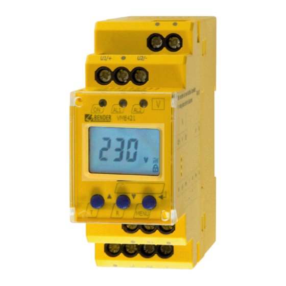
- Page 1 Manual VME421H-DM Voltage and frequency monitor for monitoring AC/DC systems for undervoltage, overvoltage, underfrequency and overfrequency Software version VME421H-DM-1: D236 V2.2x Software version VME421H-DM-2: D237 V2.2x VME421H-DM_D00150_01_M_XXEN/02.2015...
- Page 2 Postfach 1161 • 35301 Gruenberg • Germany Tel.: +49 6401 807-0 Fax: +49 6401 807-259 Email: info@bender.de www.bender.de © Bender GmbH & Co. KG All rights reserved. Reprinting only with permission of the publisher. Subject to change! Photos: Bender archives and bendersystembau archives.
-
Page 3: Table Of Contents
Table of Contents 1. How to use this operating manual effectively ........... 5 How to use this manual ................. 5 Intended use ...................... 6 Fast commissioning for Un = 230 V, 50 Hz ..........6 2. Safety information ................... 9 General safety information ................ - Page 4 5.5.13 History memory query ................. 33 Preset function/ factory setting ............... 34 Commissioning ....................34 6. Technical data VME421H-DM… ..............35 Current and voltage curves of the analogue interface ....39 Standards, approvals and certifications ..........40 Ordering information ................... 40...
-
Page 5: How To Use This Operating Manual Effectively
1. How to use this operating manual effectively 1.1 How to use this manual This manual is intended for experts in electrical engineering and electronics! In order to make it easier for you to find specific text passages or references in this manual and for reasons of comprehensibility, important information is emphasized by symbols. -
Page 6: Intended Use
How to use this operating manual effectively 1.2 Intended use The voltage monitor VME421H-DM monitors AC/DC systems in the frequency range of DC/15…460 Hz for undervoltage, overvoltage, underfrequency or overfrequency. Device variant -1 is suitable for the nominal voltage range = 9.6…150 V, device variant -2 for U... - Page 7 4. When the conditions 1, 2 and 3 are satisfied, you can connect the vol- tage monitor to the system to be monitored according to the wiring diagram (page 16). The following predefined response values will be set automatically: VME421H-DM-2 Preset Response Response...
- Page 8 How to use this operating manual effectively VME421H-DM_D00150_01_M_XXEN/02.2015...
-
Page 9: Safety Information
2.1 General safety information In addition to this data sheet, the documentation of the device includes a sheet entitled "Important safety instructions for Bender products". 2.2 Work activities on electrical installations All work activities necessary for installation, commissioning or work ... - Page 10 Safety information VME421H-DM_D00150_01_M_XXEN/02.2015...
-
Page 11: Function
3. Function 3.1 Device features Undervoltage and overvoltage monitoring of AC/DC systems in the frequency range DC/15…460 Hz device variant -1: 9.6…150 V device variant -2: 70…300 V Preset function: Automatic response value setting for undervoltage and overvoltage, <... -
Page 12: Function
+ 1 Hz Response value underfrequency ( < f) at 16.7 Hz, 50 Hz, 60 Hz: f - 1 Hz Response value underfrequency ( < f) at 400 Hz: f - 1 Hz Preset VME421H-DM-2 Preset Response value Response value Device operating range <... -
Page 13: Automatic Self Test
3.2.4 Functional faults If an internal malfunction occurs, all three LEDs flash. An error code will appear on the display (E01…E32). In such a case please contact the Bender Service. 3.2.5 Fault memory The fault memory can be activated, deactivated or can be set to continuous mode (con). -
Page 14: Password Protection (On, Off)
One of three output signals can be selected from the associated menu. Only use the output you have selected via the software: – DC 0…400 μA Current output for Bender measuring instruments of the 96… series – DC 0/4…20 mA Standardised current output with selectable current ranges –... -
Page 15: Installation And Connection
4. Installation and connection Ensure safe isolation from supply in the installation area. Observe the installation rules for live working. DANGER General dimension diagram and drawing for screw fixing The front plate cover is easy to open at the lower part identified by an arrow. VME421H-DM_D00150_01_M_XXEN/02.2015... - Page 16 Installation and connection 1. DIN rail mounting: Snap the rear mounting clip of the device into place in such a way that a safe and tight fit is ensured. Screw fixing: Use a tool to move the rear mounting clips (a second mounting clip is required, see ordering information) to a position that it projects bey- ond the enclosure.
- Page 17 Installation and connection Terminal Connections Connection to the system being U1/+, U2/- monitored (common) positive pole of the analogue interface Current output 0…400 μA μA Current output 0/4…20 mA Voltage output 0…10 V 10 V VME421H-DM_D00150_01_M_XXEN/02.2015...
- Page 18 Installation and connection VME421H-DM_D00150_01_M_XXEN/02.2015...
-
Page 19: Operation And Setting
5. Operation and setting 5.1 Display elements in use A detailed description of the meaning of the display elements is given in the table below. Display elements in use Element Function Undervoltage (Alarm 2), < U, Overvoltage (Alarm 1) > U Response value hysteresis U U Hys, as %... -
Page 20: Function Of The Operating Elements
Operation and setting 5.2 Function of the operating elements Device front Element Function Power On LED, green LED Alarm 1 lights (yellow): AL1 AL2 Response value > U reached LED Alarm 2 lights (yellow): Res- ponse value < U reached Both LEDs light when the frequency AL1 and response values >... -
Page 21: Menu Structure
Operation and setting 5.3 Menu structure All adjustable parameters are listed in the columns "menu item" and "adjusta- ble parameters". A display-like representation is used to illustrate the param- eters in the column menu item. Menu Acti- Menu Adjustable parameter menu item vation... -
Page 22: Display In Standard Mode
Operation and setting Start-up delay (timing check) Parameter setting via pass- word Restore factory settings (device con- trol) Manual preset Function blocked Display hard / software version History memory for the first alarm value, erasable 5.4 Display in standard mode By default, the voltage applied across the terminals U1/+ and U2/- is indicated on the display. -
Page 23: Display In Menu Mode
Operation and setting 5.5 Display in menu mode 5.5.1 Parameter query and setting: overview Menu item Adjustable parameter Querying and setting response values: – Undervoltage: < U (AL2) – Overvoltage: > U (AL1) – Hysteresis of the voltage response values: Hys U –... - Page 24 Operation and setting Menu structure VME421H-DM_D00150_01_M_XXEN/02.2015...
-
Page 25: Response Value Setting For Undervoltage, Overvoltage And Hysteresis
Operation and setting Parameter setting An example on how to change the alarm response value for overvoltage > U is given below. Proceed as follows: 1. Press the MENU/Enter key for more than 1.5 s. The flashing short sym- bol AL appears on the display. 2. - Page 26 Operation and setting Response value setting for undervoltage < U Response value setting for overvoltage > U Set the hysteresis for the voltage response values VME421H-DM_D00150_01_M_XXEN/02.2015...
-
Page 27: Response Value Setting For Underfrequency, Overfrequency And Hysteresis
Operation and setting 5.5.3 Response value setting for underfrequency, overfrequency and hysteresis Set the response value for underfrequency < Hz Set the response value for overfrequency > Hz VME421H-DM_D00150_01_M_XXEN/02.2015... -
Page 28: Deactivating The Fault Memory
Operation and setting Set the hysteresis for the frequency response values 5.5.4 Deactivating the fault memory 5.5.5 Selecting the output current range of the analogue interface 0.20 mA stands for 0…20 mA 4.20 mA stands for 4…20 mA VME421H-DM_D00150_01_M_XXEN/02.2015... -
Page 29: Selecting The Voltage Output Of The Analogue Interface
Operation and setting 5.5.6 Selecting the voltage output of the analogue interface 0.04 mA stands for 0…400 μA 5.5.7 Setting the 100% reference of the analogue interface Set here to which reference value the 100% value of the output signal is to be connected. -
Page 30: Setting The Start-Up Delay T
Operation and setting 5.5.8 Setting the start-up delay Use this menu to set the start-up delay t (0…300 s) for device start. 5.5.9 Factory setting and password protection Use this menu to activate the password protection, to change the password or to deactivate the password protection. - Page 31 Operation and setting b) Changing the password c) Disabling the password protection VME421H-DM_D00150_01_M_XXEN/02.2015...
-
Page 32: Restoring Factory Settings
Operation and setting 5.5.10 Restoring factory settings 5.5.11 Activating the preset function manually 5.5.12 Device information query This function is used to query the hardware (d…) and software (1.xx) versions. After activating this function, data will be displayed as a scrolling text. VME421H-DM_D00150_01_M_XXEN/02.2015... -
Page 33: History Memory Query
Operation and setting Once one pass is completed, you can select individual data sections using the Up/Down keys. 5.5.13 History memory query The history memory can be selected via the menu HiS. Use the Up and Down keys to view the next display. If Clr is flashing, the history memory can be cleared with the Enter key. -
Page 34: Preset Function/ Factory Setting
0, Off 5.7 Commissioning Prior to commissioning, check proper connection of the voltage monitor. After connecting a brand-new VME421H-DM-2 to a standard system of U = 230 V / 50 Hz, the response values are automatically set by the internal preset function:... -
Page 35: Technical Data Vme421H-Dm
..................no (internal supply from U : 70…300 V)) Power consumption ............................≤ 6 VA Measuring circuit Measuring range (r.m.s.) (VME421H-DM-1) ................AC / DC 0…150 V Measuring range (r.m.s.) (VME421H-DM-2)................AC / DC 0…300 V Rated frequency f ..........................DC, 15…460 Hz Frequency range ............................ - Page 36 ............................. t Discharging time energy backup on power failure (VME421H-DM-1) ............. on request Discharging time energy backup on power failure (VME421H-DM-2) ..........≥ 2s at DC 70 V .............................. ≥ 4 s at DC 80 V / AC 70 V Charging time energy backup (VME421H-DM-1) ..................
- Page 37 Technical data VME421H-DM… Displays, memory Display..................... LC display, multi-functional, not illuminated Display range, measuring value (VME421H-DM-1) ............... AC/DC 0…150 V Display range, measuring value (VME421H-DM-2) ............... AC/DC 0…300 V Operating uncertainty voltage, at 50/60 Hz ..................±1.5 %, ±2 digit Operating uncertainty voltage, at 15…460 Hz .................
- Page 38 Flammability class ............................UL94 V-0 DIN rail mounting acc. to..........................IEC 60715 Screw fixing ......................... 2 x M4 with mounting clip Software version VME421H-DM-1 ......................on request Software version VME421H-DM-2 ......................D237 V2.2x Weight ................................≤ 240 g ( )* = factory setting ** = The technical data applies to the operating range of the rated frequency (15…460 Hz) only.
-
Page 39: Current And Voltage Curves Of The Analogue Interface
Technical data VME421H-DM… 6.1 Current and voltage curves of the analogue interface Current output 0/4…20 mA Current output 0…400 μA Current output 0…10 V VME421H-DM_D00150_01_M_XXEN/02.2015... -
Page 40: Standards, Approvals And Certifications
Technical data VME421H-DM… 6.2 Standards, approvals and certifications 6.3 Ordering information Nominal voltage n Device type Art. No. AC/DC 9.6…150 V VME421H-DM-1 on request 15…460 Hz AC/DC 70…300 V B 9301 0010 VME421H-DM-2 15…460 Hz VME421H-DM-2 AC/DC 70…300 V B 7301 0010 (push-wire 15…460 Hz... - Page 41 INDEX Adjustable parameters, list 21 How to use this manual 5 Automatic self test 13 Installation and connection 15 currently measured values - Nominal voltage 22 LED Alarm 1 lights 20 - rated frequency 22 LED Alarm 2 lights 20 Deleting the fault alarms 20 Manual self test 13 Device features 11...
- Page 42 Parameter query and setting - 23 Parameter setting - Activating or deactivating the pass- word protection 30 - Deactivate fault memory 28 - Response value setting 25 Password protection 14 Preset function 12 Reset button 20 Response value setting - Hysteresis frequency 28 - Hysteresis U 26 - Overfrequency (>...
- Page 44 Bender GmbH & Co. KG Londorfer Str. 65 • 35305 Gruenberg • Germany Postfach 1161 • 35301 Gruenberg • Germany Tel.: +49 6401 807-0 Fax: +49 6401 807-259 Email: info@bender.de www.bender.de Photos: Bender archives and bendersystembau archives.
Need help?
Do you have a question about the VME421H-DM and is the answer not in the manual?
Questions and answers