Table of Contents
Advertisement
Quick Links
Assembly & User Manual
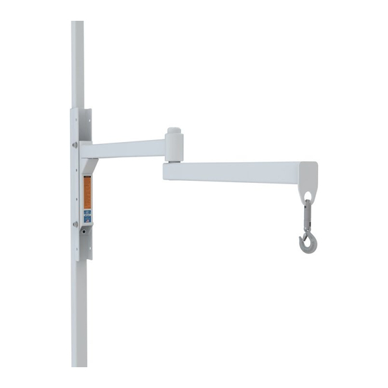
ORBIT
Patient Transfer Lift
®
SHOWN WITH OPTIONAL SWIVEL HOOK
Anchoring hardware is not included.
Patented.
5-YEAR WARRANTY. Please register at www.ezaccess.com/warranty-satisfaction.
© EZ-ACCESS
®
, a division of Homecare Products, Inc. All rights reserved.
All text and images contained in this document are proprietary and may not be shared, modified,
17534 REV 11-30-2020
distributed, reproduced, or reused without the express written permission of EZ-ACCESS.
Advertisement
Table of Contents

Related Manuals for EZ-ACCESS ORBIT


Summary of Contents for EZ-ACCESS ORBIT
- Page 1 , a division of Homecare Products, Inc. All rights reserved. All text and images contained in this document are proprietary and may not be shared, modified, 17534 REV 11-30-2020 distributed, reproduced, or reused without the express written permission of EZ-ACCESS.
-
Page 2: Table Of Contents
Models have a horizontal reach of up to 5’ in all directions, as well as to accommodate ceiling heights of 7’–9’ and 8’–12’. The ORBIT rotates a full 360-degrees at the stanchion as well as 360-degrees at the articulating arm. -
Page 3: Tools Typically Required
The articulating arm swings freely; a qualified helper must always maintain control of patient. Before each use, check the ORBIT for worn, loose, missing, unstable, or damaged parts. If you find any of these conditions, do not use. Consult with a professional contractor if you need assistance or additional information. -
Page 4: Section 1: Getting Started
ORBIT. 1.3. Before each use, check the ORBIT for worn, loose, missing, unstable, or damaged parts. If you find any of these conditions, do not use. Consult with a professional contractor if you need assistance or additional information. -
Page 5: Section 3: Labels
LABELS The ORBIT has warning and brand labels (FIG. 3.1). Labels may vary in placement, color, size, and written content. Maintaining all labels in legible condition is required and is essential for safe operation. For replacement copies, call 1-800-451-1903. WARNING LABEL FIG. - Page 6 FIG. 4.1 FIG. 4.2 Page | 6 EZ-ACCESS® ORBIT™ Patient Transfer Lift...
- Page 7 4.1.8. Refer to TABLE 4.1 for anchor and structural information. 4.1.9. Once anchoring is complete, torque all 4 stanchion set screws (FIG 4.2) to 25 ft./lbs. FIG. 4.3 FIG. 4.4 Page | 7 EZ-ACCESS® ORBIT™ Patient Transfer Lift...
-
Page 8: Anchor & Structural Information
Anchoring construction must be structurally sound and hold ORBIT without failure. Professional installation by a contractor is recommended. An improperly anchored ORBIT can be an extreme hazard. The installer must decide which anchoring hardware and method is best for your circumstances. -
Page 9: Articulating Arm
FIG. 4.5 recommendations. Do not exceed the ORBIT Rated Load of 440 lbs. 4.2.3. The arm fits inside of the hanger (FIG. 4.6) and is bolted in place. After determining the working height of the arm, secure it into 2 of the pre-drilled anchor holes using 2-each 1/2”-13 X 3.5” cap screws, 2-each 1/2”-13 locknuts, and 4-each 1/2”... -
Page 10: Set & Adjust Pitch
4.4.1. The 1/2" brake set screw (FIG 4.1 and FIG. 4.9) increases/decreases the stanchion’s rotational drag (the resistance of the stanchion to the pushing and pulling of the ORBIT operator). Drag is used to provide the operator more control over stanchion rotation; the stanchion rotation will follow the articulating arm’s lead. -
Page 11: Section 5: Swivel Hook (Optional)
FIG. 5.1 FINAL CHECKS & MAINTENANCE 6.1. Test the full range of ORBIT motion and ensure that no potentially dangerous conditions exist. 6.2. Ensure that all fasteners are in place and secure. 6.3. Before performing any transfer, ensure that clear space is maintained around the ORBIT (remove all furniture and other obstructions).
Need help?
Do you have a question about the ORBIT and is the answer not in the manual?
Questions and answers