Advertisement
Quick Links
INSTRUCTIONS FOR RUBBER THRESHOLD RAMP
BEFORE YOU BEGIN
Maximum weight limit is 850 pounds.
1.
Read and follow all instructions before use. Do not use if ramp is
2.
damaged or unstable.
For use with wheelchairs and scooters only. Ramp is intended for
3.
residential use.
IMPORTANT: Use ramp only with a qualified helper and always use
4.
your lap belt.
WARNING: It is important that you refer to your equipment's
5.
(wheelchair or scooter) Owner Guide for the proper degree of
incline/decline and chair direction before using ramp. Never exceed its
recommendations.
FITTING A RUBBER THRESHOLD RAMP: Ramp can be easily trimmed to
accommodate lower heights and narrower widths and, if necessary, notched
to suit the doorjamb configuration. Alternately, ramp can be combined with
an additional Rubber Threshold Ramp and one set of Rubber Risers to
create a maximum height of 4¾".
If door threshold is equal to the height of the Rubber Threshold Ramp
1.
(2½" high), use Threshold Ramp as is (see
If door threshold is less than the height of the Rubber Threshold Ramp
2.
(2½" high), trim ramp to the desired height, depth and/or width using a
reciprocating saw, razor knife, or hand saw (see
WARNING: Use caution when operating any non-manual saw as
serious injury may result due to unexpected binding or pinching of rubber
ramp material. Always follow tool manufacturer's safety guidelines.
If door threshold is greater than the height of the Rubber Threshold
3.
Ramp (2½" high), two Rubber Threshold Ramps (as shown in
sections A & B) along with one pair of Threshold Risers
DIAGRAM 2,
(
DIAGRAM 2
, section C) can be combined to accommodate a rise up to
4¾" high.
a. When creating greater heights, an additional Rubber Threshold
Ramp (Section B of
configuration, Section A must remain at its original height (ok to
trim width only).
b. Section B, as shown in
height, depth and/or width. If Section B is trimmed, the Rubber
Riser (Section C), used to increase overall height, needs to be
trimmed to match the depth of Section B.
c. Secure Section B to Section C using supplied Phillips Head
Screws.
DIAGRAM 2
6450 REV 07-24-08
DIAGRAM
DIAGRAM
) will be used. NOTE: With this
DIAGRAM 2
DIAGRAM 2
, can be trimmed to the desired
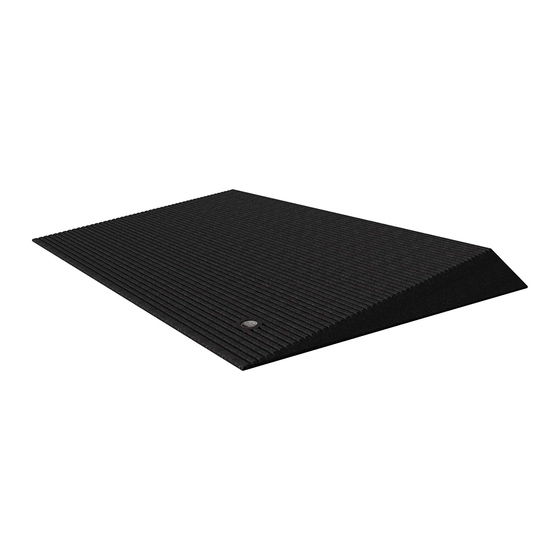
RUBBER THRESHOLD RAMP
Available in 2½" height (optional Risers also offered)
SECURING THE RAMP: It is recommended that the Rubber
Threshold ramp be secured to the surface it is laying upon.
ATTACHING TO WOOD
1.
a.
b.
ATTACHING TO CONCRETE
2.
a.
b.
c.
2, section A).
d.
1).
e.
DIAGRAM 1
and CARGO WEDGE
Place ramp in desired location and ensure that surface is
free of dirt and debris.
Secure ramp using supplied Phillips head screws (2
each). Space screws evenly (see DIAGRAM 2 for
placement) and drive until head is ¼" below the ramp
surface.
Place ramp in desired location and ensure that surface is
free of dirt and debris.
Secure ramp using supplied Phillips head screws and
concrete anchors (2 each).
Place a cardboard template under the ramp, then install
screws in locations shown in DIAGRAM 2. Drive screws
until they penetrate the cardboard template (top of screw
will be roughly ¼" below the ramp surface).
Remove ramp, but DO NOT REMOVE SCREWS. Using
the holes made in the cardboard as a guide, drill anchor
holes into concrete using a 5/16" masonry bit.
Remove template, then insert anchors into concrete.
Drive each screw into anchor until the screw head is ¼"
below the ramp surface.
One-year limited warranty. Call 253-249-1101 for details.
© 2007-2008 Homecare Products, Inc. All rights reserved.
Advertisement

Related Manuals for EZ-ACCESS RUBBER THRESHOLD RAMP


Summary of Contents for EZ-ACCESS RUBBER THRESHOLD RAMP
- Page 1 4¾”. until they penetrate the cardboard template (top of screw If door threshold is equal to the height of the Rubber Threshold Ramp will be roughly ¼” below the ramp surface). (2½” high), use Threshold Ramp as is (see 2, section A).
- Page 2 Not intended for commercial use. FITTING THE RUBBER CARGO WEDGE The EZ-ACCESS Rubber Cargo Wedge can be easily trimmed to accommodate lower heights and narrower widths and notched to suit the desired configuration using a reciprocating saw, razor knife, or hand saw.
Need help?
Do you have a question about the RUBBER THRESHOLD RAMP and is the answer not in the manual?
Questions and answers