Table of Contents
Advertisement
Quick Links
Instructions
GATEWAY
3G
®
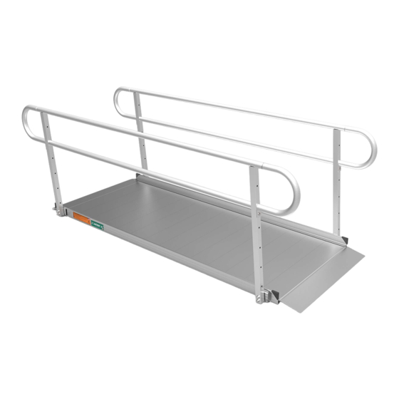
Solid Surface Portable Ramp
Portable ramp for temporary or semi-permanent use. Available
with or without handrails.
Ramp Only (w/o Handrails)
Ramp w/ Two-line Handrails
Ramp w/ Vertical Picket Handrails
LIFETIME WARRANTY. Please register at www.ezaccess.com/warranty-satisfaction.
© EZ-ACCESS
®
, a division of Homecare Products, Inc. All rights reserved.
All text and images contained in this document are proprietary and may not be shared, modified,
17838 REV 04-28-2022
distributed, reproduced, or reused without the express written permission of EZ-ACCESS.
Advertisement
Table of Contents

Related Manuals for EZ-ACCESS GATEWAY 3G


Summary of Contents for EZ-ACCESS GATEWAY 3G
- Page 1 , a division of Homecare Products, Inc. All rights reserved. All text and images contained in this document are proprietary and may not be shared, modified, 17838 REV 04-28-2022 distributed, reproduced, or reused without the express written permission of EZ-ACCESS.
- Page 2 Throughout these instructions, the GATEWAY 3G Solid Surface Portable Ramp is also referred to as ‘ramp’ and includes the ramp, handrails (if purchased), and any/all components and hardware that are intended to be assembled on the ramp.
-
Page 3: Getting Started
If damaged or missing parts are noted, do not use the ramp. PACKAGE CONTENTS Contents may vary depending on options purchased. DESCRIPTION IMAGE (NOT SHOWN TO ACTUAL SIZE) EZ-ACCESS® GATEWAY® 3G SOLID SURFACE PORTABLE RAMP CLEVIS PIN CORNER PROTECTIVE CAP HANDRAIL: TWO-LINE... -
Page 4: Care And Maintenance
PACKAGE CONTENTS, CONT’D. LOWER END LOOP Shown with O-ring and Attachment Screw (If handrails were purchased) SCREW 1/4” Self-drilling, Self-tapping Hex Washer Head (If handrails were purchased) O-ring (If handrails were purchased) INSTRUCTIONS AVAILABLE RAMP LENGTHS AND STYLES 4.1 The ramp is available in 3-, 4-, 5-, 6-, 7-, 8-, 9-, and 10-ft. lengths and comes with a self-adjusting lower transition plate and a fixed top lip transition plate. - Page 5 INSTALLING HANDRAILS 6.1 If you did not purchase the ramp with handrails, skip ahead to the ‘SETUP AND USE’ section. If walking on the ramp, handrails are required and must be installed. Regardless of the handrail style, attaching handrails to the ramp follows the same process. 6.2 Place the walking surface side of the ramp face down, onto cardboard or lawn so that the ramp is not damaged (scratched or dented).
- Page 6 6.5 Ramp handrail posts each have two holes that correspond with the studs on the brackets. Place the side with the holes onto the bracket studs (FIG. 5). Handrails are interchangeable from side to side. 6.5.1 Attach using (2 ea.) 5/16” washers and 5/16”-18 nuts per handrail post. Tighten securely with 1/2”...
- Page 7 INSTALLING HANDRAIL END LOOPS Ramps ordered with optional handrails – two-line or vertical pickets – feature end loops which are added at both the upper and lower ends of each handrail (FIG. 6). 7.1.1 FIG. 6 shows loops installed on a two-line handrail. However, the installation process is the same for both handrail styles.
- Page 8 7.1.4 Place one O-ring over the swaged portion of the end loop, then push until it rests against the loop shoulder (FIG. 9). 7.1.5 Repeat for all end loops. FIG. 9 7.1.6 Using a 1/4" driver of choice, install one 1/4” self-drilling, self-tapping hex washer head screw through the hole in the end loop attachment plate and into the handrail post (FIG.
-
Page 9: Setup And Use
SET UP AND USE Place the ramp’s top lip transition plate (identifiable by its two pre-drilled holes) onto the upper landing. Ensure that the surface area of the top lip transition plate fully overlaps a secure, unobstructed, level landing enough to safely install provided clevis pins or other non-provided anchoring hardware, and rests firmly against the upper landing (FIG. -
Page 10: Final Steps
For the safety of all users, it is important to keep your system clear of snow, ice, and other debris. Always follow the deicing agent manufacturer’s directions. EZ-ACCESS will not be held responsible for any injuries or damages that arise from the information provided. ALWAYS check with the deicing product’s manufacturer or your local supplier to determine which method is best for your situation. - Page 11 INCLINE CHART An incline chart is provided below, however, it is intended only as a guideline. Before use with mobility equipment, refer to your mobility equipment's owner guide for acceptable ramp usage, including proper slope/incline, chair direction, etc.; never exceed its recommendations. TO ESTABLISH THE PROPER RAMP LENGTH Determine the incline that your chair is designed to climb.
Need help?
Do you have a question about the GATEWAY 3G and is the answer not in the manual?
Questions and answers