Sign In
Upload
Download
Add to my manuals
Delete from my manuals
Share
URL of this page:
HTML Link:
Bookmark this page
Add
Manual will be automatically added to "My Manuals"
Print this page
×
Bookmark added
×
Added to my manuals
Manuals
Brands
Ingersoll-Rand Manuals
Power Screwdriver
1R Series
Maintenance information
Ingersoll-Rand 1R Series Maintenance Information
Air screwdrivers
Hide thumbs
Also See for 1R Series
:
Product information
(56 pages)
1
2
3
4
5
6
7
8
9
10
11
12
page
of
12
Go
/
12
Bookmarks
Advertisement
Quick Links
Download this manual
16575243
Edition 2
October 2013
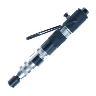
Air Screwdrivers
1R Series
Maintenance Information
Save These Instructions
Previous
Page
Next
Page
1
2
3
4
5
Advertisement
Need help?
Do you have a question about the 1R Series and is the answer not in the manual?
Ask a question
Questions and answers
Related Manuals for Ingersoll-Rand 1R Series
Power Screwdriver Ingersoll Rand 1R Series Product Information
Air screwdriver and angle wrench (56 pages)
Power Screwdriver Ingersoll-Rand 1RL Series Maintenance Information
Reversible angle screwdrivers and angle wrenches (12 pages)
Power Screwdriver Ingersoll-Rand 1RLN Maintenance Information
Air screwdrivers (12 pages)
Power Screwdriver Ingersoll-Rand QX Series Product Information
Cordless screwdriver and nutrunner (116 pages)
Power Screwdriver Ingersoll-Rand QS Series Instructions Manual
Inline push–to–start screwdrivers (61 pages)
Power Screwdriver Ingersoll-Rand QS1L Series Operation And Maintenance Manual
Lever inline screwdrivers (35 pages)
Power Screwdriver Ingersoll-Rand QX Series Product Information
Cordless screwdriver and nutrunner (96 pages)
Power Screwdriver Ingersoll-Rand 5 Series Operation And Maintenance Manual
Air screwdrivers (21 pages)
Power Screwdriver Ingersoll Rand 5RALC1-EU Product Information
Air screwdriver (64 pages)
Power Screwdriver Ingersoll-Rand 3R Series Operation And Maintenance Manual
Air screwdrivers (45 pages)
Power Screwdriver Ingersoll-Rand QE4 Pistol Product Information
Hand-held electric screwdriver or nut runner used with a controller (52 pages)
Power Screwdriver Ingersoll-Rand QX Connect Series Programming Manual
(12 pages)
Power Screwdriver Ingersoll-Rand QX Series Maintenance Information
Cordless drill/driver (24 pages)
Power Screwdriver Ingersoll-Rand QP1P Series Maintenance Information
Air screwdrivers (9 pages)
Power Screwdriver Ingersoll-Rand 371 Instructions Manual
Positive jaw clutch reversible screwdrivers (21 pages)
Power Screwdriver Ingersoll-Rand QC Series Product Information
Cordless screwdriver and nutrunner (92 pages)
This manual is also suitable for:
1rl
1rp
1rt
1rlm
1rln
1ra
...
Show all
1rpns1-ir
1rlnc1-ir
1rlmc1-ir
Print
Rename the bookmark
Delete bookmark?
Delete from my manuals?
Login
Sign In
OR
Sign in with Facebook
Sign in with Google
Upload manual
Upload from disk
Upload from URL


Need help?
Do you have a question about the 1R Series and is the answer not in the manual?
Questions and answers