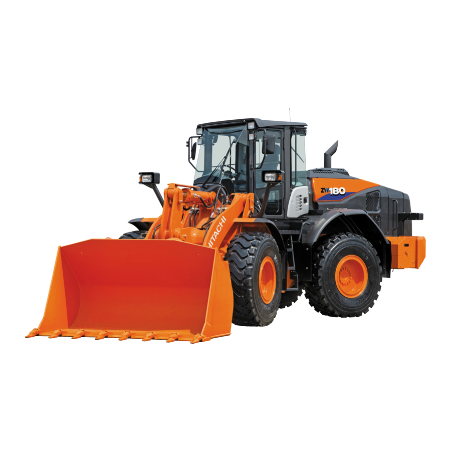
Hitachi ZW180 Operator's Manual

Hitachi ZW180 Operator's Manual

Wheel loader
Hide thumbs Also See for ZW180:
Table of Contents

Advertisement

Quick Links

EM4GF-EN2-1
PART NO.
180
220
250
310
Wheel Loader
URL:http://www.hitachi-c-m.com
PRINTED IN EUROPE (ACI) 2007, 06
Serial No 005101 and up

Advertisement

Table of Contents
loading

Summary of Contents for Hitachi ZW180

  • Page 1 EM4GF-EN2-1 PART NO. Wheel Loader URL:http://www.hitachi-c-m.com PRINTED IN EUROPE (ACI) 2007, 06 Serial No 005101 and up...
  • Page 2 INTRODUCTION Read this manual carefully to learn how to operate and Warranty is provided as a part of Hitachi’s support service your machine correctly. Failure to do so could program for customers who operate and maintain their result in personal injury or machine damage.
  • Page 3 ENGIN EMISSION CONTROL LABEL INDEX MACHINE NUMBERS SAFETY SAFETY SIGNS COMPONENTS NAME OPERATOR'S STATION BREAK-IN OPERATING THE ENGINE DRIVING THE MACHINE OPERATING THE MACHINE TRANSPORTING MAINTENANCE MAI N TENANCEUNDERSPECI A LENVI R ONMENTALCONDI T I O NS STORAGE TROUBLESHOOTING SPECIFICATIONS OPTIONAL ATTACHMENTS INDEX EM4GF-EN2-1...
  • Page 5 ENGINE EMISSION CONTROL LABEL ZW180 EMISSION CONTROL LABEL: ENGINE LABEL (FOR EPA) Emission control label is attached on the cylinder head cover. EC EMISSION CONTROL LABEL: ENGINE LABEL...
  • Page 6 ENGINE EMISSION CONTROL LABEL ZW220, ZW250 EMISSION CONTROL LABEL: ENGINE LABEL (FOR EPA) Emission control label is attached on the cylinder head cover. The following is the sample of a label required for engin emission control information, along with location. EC EMISSION CONTROL LABEL: ENGINE LABEL Emission control label is attached on the cylinder head cover.
  • Page 7 ENGINE EMISSION CONTROL LABEL ZW310 EMISSION CONTROL LABEL: ENGINE LABEL (FOR EPA) Emission control label is attached on the cylinder head cover. EC EMISSION CONTROL LABEL: ENGINE LABEL...
  • Page 8 MACHINE SAMPLE M4GB-00-001 1. MODEL/TYPE 2. Product Identification Number ZW180 3. Year of Manufacturing M4GF-00-003 4. Operating mass (standard version) 5. Engine power in kW according to ISO9249 PRODUCT INDENTIFICATION NUMBER PRODUCT...
  • Page 9: Table Of Contents

    CONTENTS ENGIN EMISSION CONTROL LABEL Replace Rubber Hoses Periodically ........S-24 Avoid High-pressure Fluids ............S-25 Prevent Fires ................... S-26 MACHINE NUMBERS Evacuating In Case Of Fire ............S-27 Beware Of Exhaust Fumes ............S-27 SAFETY Precautions For Welding And Grinding ........ S-27 Recognize Safety Information ...........
  • Page 10 Rotary Light Switch (Optional) .........1-78 Hazard Switch .................1-32 Rear View Mirror ................1-79 Work Light Switch ..............1-33 Room Mirror ...................1-79 Driving Mode Switch (ZW180) ..........1-34 Cab Door ..................1-79 Driving Mode Switch (ZW220, ZW250, ZW310) ..1-35 Door Lock Knob ................1-80 Clutch Cut Position Switch ..........1-36 Door Open/Close Lever ..............1-80...
  • Page 11 CONTENTS Finger Type ..................4-7 B. Engine ..................7-28 Multi-Function Type ..............4-7 Check Engine Oil Level ............7-28 Steering ....................4-8 Change Engine Oil ..............7-28 Provisional Stop and Restart of Driving ......4-9 Replace Engine Oil Filter .............7-30 Precautions for Driving on Slopes ..........4-11 C.
  • Page 12 CONTENTS Check Wheel Bolt Torque ............7-86 K. Air Conditioner .................7-90 Clean/Replace Air Conditioner Circulation/ Fresh Air Filters ...............7-90 Check Air Conditioner ............7-92 Check Air Conditioner Piping ..........7-92 Check Air Conditioner Condenser ........7-93 Check Air Conditioner Fan Belt .........7-93 Check Refrigerant ..............7-94 Check Compressor and Pulley ..........7-94 Check Switch Operation .............7-94 L.
  • Page 13: Safety

    SAFETY RECOGNIZE SAFETY INFORMATION • These are the SAFETY ALERT SYMBOLS. • When you see these symbols on your machine or in this manual, be alert to the potential for personal injury. • Follow recommended precautions and safe operating practices. 001-E01A-0001 SA-688 UNDERSTAND SIGNAL WORDS...
  • Page 14: Follow Safety Instructions

    Hitachi Warranty Policy. • Do not use attachments and/or optional parts or equip- ment not authorized by Hitachi. Failure to do so may deteriorate the safety, function, and/or service life of the machine. In addition, personal accident, machine trouble,...
  • Page 15: Wear Protective Clothing

    SAFETY WEAR PROTECTIVE CLOTHING • Wear close fitting clothing and safety equipment appropri- ate to the job. You may need: A hard hat Safety shoes Safety glasses, goggles, or face shield Heavy gloves Hearing protection Reflective clothing SA-438 Wet weather gear Respirator or filter mask.
  • Page 16: General Precautions For Cab

    SAFETY GENERAL PRECAUTIONS FOR CAB • Before entering the cab, thoroughly remove all dirt and/ or oil from the soles of your work boots. If any controls such as a pedal is operated while with dirt and/or oil on the soles of the operator’s work boots the operator’s foot may slip off the pedal, possibly resulting in a personal ac- cident.
  • Page 17: Use Handholds And Steps

    SAFETY USE HANDHOLDS AND STEPS • Falling is one of the major causes of personal injury. • When you get on and off the machine, always face the machine and maintain a three-point contact with the steps and handrails. • Do not use any controls as hand-holds. •...
  • Page 18: Fasten Your Seat Belt

    SAFETY FASTEN YOUR SEAT BELT • If the machine should overturn, the operator may become injured and/or thrown from the cab. Additionally the opera- tor may be crushed by the overturning machine, resulting in serious injury or death. • Prior to operating the machine, thoroughly examine web- bing, buckle and attaching hardware.
  • Page 19: Operate Only From Operator's Seat

    SAFETY OPERATE ONLY FROM OPERATOR'S SEAT • Inappropriate engine starting procedures may cause the machine to runaway, possibly resulting in serious injury or death. • Start the engine only when seated in the operator's seat. • NEVER start the engine while standing on the track or on ground.
  • Page 20: Investigate Job Site Beforehand

    SAFETY INVESTIGATE JOB SITE BEFOREHAND • When working at the edge of an excavation or on a road shoulder, the machine could tip over, possibly resulting in serious injury or death. • Investigate the configuration and ground conditions of the job site beforehand to prevent the machine from fall- ing and to prevent the ground, stockpiles, or banks from collapsing.
  • Page 21: Equipment Of Head Guard, Rops, Fops

    SAFETY EQUIPMENT OF HEAD GUARD, ROPS, FOPS In case the machine is operated in areas where the possibility of falling stones or debris exist, equip a head guard, ROPS, or FOPS according to the potential hazardous conditions. (The standard cab for this machine corresponds to ROPS and FOPS.) ROPS: Roll-Over Protective Structure FOPS: Falling Object Protective Structure SA-521...
  • Page 22: Keep Riders Off Machine

    SAFETY KEEP RIDERS OFF MACHINE • Riders on machine are subject to injury such as being struck by foreign objects and being thrown off the machine. • Only the operator should be on the machine. Keep riders off. • Riders also obstruct the operator’s view, resulting in the machine being operated in an unsafe manner.
  • Page 23: Drive Machine Safely (Work Site

    SAFETY DRIVE MACHINE SAFELY (WORK SITE) • Before driving the machine, always confirm that the steer- ing wheel/F-N-R lever direction corresponds to the direction you wish to drive. • Be sure to detour around any obstructions. • Driving on a slope may cause the machine to slip or over- turn, possibly resulting in serious injury or death.
  • Page 24: Drive On Snow Safely

    SAFETY DRIVE ON SNOW SAFELY • Beware of the possibility of slipping or turning over the machine when driving on frozen snow surfaces. • The machine may slip more easily than expected on fro- zen snow surfaces even if the inclination is small. Reduce speed when driving.
  • Page 25: Avoid Injury From Rollaway Accidents

    SAFETY AVOID INJURY FROM ROLLAWAY ACCIDENTS • Death or serious injury may result if you attempt to mount or stop a moving machine. To avoid rollaways: • Select level ground when possible to park machine. • Do not park the machine on a grade. •...
  • Page 26: Avoid Accidents From Backing Up And Turning

    SAFETY AVOID ACCIDENTS FROM BACKING UP AND TURNING • Make sure no one is working under or close to the machine before backing up or turning the machine to avoid personal injury and/or death by being run over or entangled in the machine.
  • Page 27: Avoid Positioning Bucket Over Anyone

    SAFETY AVOID POSITIONING BUCKET OVER ANYONE • Never allow the bucket to pass over co-workers and/or the dump truck operator’s cab. Falling soil from the bucket or contact with bucket may cause serious personal accidents and/or damage to the machine. •...
  • Page 28: Never Undercut A High Bank

    SAFETY NEVER UNDERCUT A HIGH BANK • The edges could collapse or a land slide could occur causing serious injury or death. 026-E01A-0519 SA-519 DIG WITH CAUTION Before digging, check the location of cables, gas lines, and wa- ter lines. 027-E01A-0396 SA-396 PERFORM TRUCK LOADING SAFELY...
  • Page 29: Avoid Power Lines

    SAFETY AVOID POWER LINES Serious injury or death can result from contact with electric lines. Never move any part of the machine or load closer to any electric line than 3 m (10 ft) plus twice the line insulator length. 029-E01A-0455 SA-455 PRECAUTIONS FOR OPERATION...
  • Page 30: Protect Against Flying Debris

    SAFETY PROTECT AGAINST FLYING DEBRIS • If flying debris hit eyes or any other part of the body, serious injury may result. • Guard against injury from flying pieces of metal or debris; wear goggles or safety glasses. • Keep bystanders away from the working area before strik- ing any object.
  • Page 31: Store Attachments Safely

    SAFETY STORE ATTACHMENTS SAFELY • Stored attachments such as buckets, hydraulic hammers, and blades can fall and cause serious injury or death. • Securely store attachments and implements to prevent falling. Keep children and bystanders away from storage areas. 504-E01A-0034 SA-034 TRANSPORT SAFELY •...
  • Page 32: Handle Fluids Safely−Avoid Fires

    SAFETY HANDLE FLUIDS SAFELY−AVOID FIRES • Handle fuel with care; it is highly flammable. If fuel ignites, an explosion and/or a fire may occur, possibly resulting in serious injury or death. • Do not refuel the machine while smoking or when near open flame or sparks.
  • Page 33: Practice Safe Maintenance

    SAFETY PRACTICE SAFE MAINTENANCE To avoid accidents: • Understand service procedures before starting work. • Keep the work area clean and dry. • Do not spray water or steam inside cab. • Never lubricate or service the machine while it is moving. •...
  • Page 34: Warn Others Of Service Work

    SAFETY • Sufficiently illuminate the work site. Use a maintenance work light when working under or inside the machine. • Always use a work light protected with a guard. In case the light bulb is broken, spilled fuel, oil, antifreeze fluid, or window washer fluid may catch fire.
  • Page 35: Support Maintenance Properly

    SAFETY SUPPORT MAINTENANCE PROPERLY • Explosive separation of a tire and rim parts can cause seri- ous injury or death. • Do not attempt to mount a tire unless you have the prop- er equipment and experience to perform the job. Have it done by your authorized dealer or a qualified repair ser- vice.
  • Page 36: Prevent Burns

    SAFETY PREVENT BURNS Hot spraying fluids: • After operation, engine coolant is hot and under pressure. Hot water or steam is contained in the engine, radiator and heater lines. Skin contact with escaping hot water or steam can cause severe burns. •...
  • Page 37: Avoid High-Pressure Fluids

    SAFETY AVOID HIGH-PRESSURE FLUIDS • Fluids such as diesel fuel or hydraulic oil under pressure can penetrate the skin or eyes causing serious injury, blindness or death. • Avoid this hazard by relieving pressure before disconnect- ing hydraulic or other lines. •...
  • Page 38: Prevent Fires

    SAFETY PREVENT FIRES Check for Oil Leaks: • Fuel, hydraulic oil and lubricant leaks can lead to fires. • Check for oil leaks due to missing or loose clamps, kinked hoses, lines or hoses that rub against each other, damage to the oil-cooler, and loose oil-cooler flange bolts.
  • Page 39: Evacuating In Case Of Fire

    SAFETY EVACUATING IN CASE OF FIRE • If a fire breaks out, evacuate the machine in the following way: • Stop the engine by turning the key switch to the OFF po- sition if there is time. • Use a fire extinguisher if there is time. •...
  • Page 40: Avoid Heating Near Pressurized Fluid Lines

    SAFETY AVOID HEATING NEAR PRESSURIZED FLUID LINES • Flammable spray can be generated by heating near pres- surized fluid lines, resulting in severe burns to yourself and bystanders. • Do no heat by welding, soldering, or using a torch near pressurized fluid lines or other flammable materials.
  • Page 41: Beware Of Asbestos Dust

    • Keep bystanders out of the work site during operation. SA-029 • Asbestos might be present in imitation parts. Use only genuine Hitachi Parts. PREVENT BATTERY EXPLOSIONS • Battery gas can explode. • Keep sparks, lighted matches, and flame away from the top of battery.
  • Page 42: Handle Chemical Products Safely

    • Improperly disposing of waste can threaten the environ- ment and ecology. Potentially harmful waste used with HITACHI equipment includes such items as oil, fuel, coolant, brake fluid, filters, and batteries. • Use leakproof containers when draining fluids. Do not use food or beverage containers that may mislead someone into drinking from them.
  • Page 43: Safety Signs

    Use the part No. indicated under the right corner of each safety sign illustration when placing an order of it to the Hitachi dealer. ✽ 2 ZW220, ZW250 ZW310 ✽ 2 ✽ 1 ZW-0001 *1: Affixed on the ZW310 only. *2: Affixed on the ZW180, ZW220 and ZW250 only. S-31...
  • Page 44 ZW-0002 Do not stand on this place. ZW-0003 ZW-0005 ZW310 ZW180, ZW220, ZW250 ZW-0004 2. Front Maintenance Access Cover for Front Frame SS263G9-12111 • The front attachment may automatically be lowered, pos- sibly resulting in personal injury. Lower the front attachment ZW-0006 to the ground before inspecting/maintaining the machine.
  • Page 45 SAFETY SIGNS 3. Cab Inside Right Front Column (First safety sign from the top) WARNING • Prior to operation, maintenance, disassembling, and transportation of the machine, be sure to read and understand the Operator’s Manual. SS263G9-12151 ZW-0007 4. Cab Inside Right Front Column (2nd safety sign from the top) •...
  • Page 46 SAFETY SIGNS 7. Cab Inside Left Front Column ZW-0009 SS263G9-12231 S-34...
  • Page 47 • Avoid skin contact with highly heated parts such as the engine, muffler, etc. immediately after operation of the machine. Severe burns may result. ZW-0020 ZW180 SSH4407874 ZW220, ZW250 ZW-0013 9. Bottoms at Both Right and Left Side Covers of Rear Frame SS263G9-12121 •...
  • Page 48 ZW-0013 SS263G9-12571 12. Flank of Engine Starter SS263G9-12221 • If the engine is started following an incorrect method, the machine suddenly may start to move. Start the engine from ZW180 ZW-0022 the operator’s seat only. ZW310 ZW-0015 ZW220, ZW250 ZW-0014 13.
  • Page 49 Allow radiator or hydraulic tank to cool before removing cap. ZW-0017 15. Inside Battery Box (Outward) • Skin contact with electrolyte will cause burns. Splashed electrolyte into eyes will cause blindness. Take care not to touch electrolyte. ZW-0021 ZW180 SS263G9-12191 ZW-0008 ZW220, 250, 310 S-37...
  • Page 50 16. Inside Battery Box (Center) • Sign indicates an explosion hazard. Keep fire and open flames away from this area. SS263G9-12181 ZW-0021 ZW180 ZW-0008 ZW220, 250, 310 17. Inside Battery Box (Inward) • Sign indicates an electrical hazard from handling the cable. Read man- ual for safe and proper handling.
  • Page 51 SAFETY SIGNS 18. Both Sides of Front Frame SS263G9-12061 • The articulation area becomes a pinch point when steering the machine. Keep all personnel away from the articulation area during operation of the machine. ZW-0011 19. Both Sides of Lift Arm SS263G9-12071 •...
  • Page 52 SAFETY SIGNS MEMO ..............................................................................................................................................................................................................................................................................................................................................................................................................................................................................................................................................................................................................................................................................................................................................................................................................................................................................................................................................................................................................................................................................................................................................................................................................................................................................................................................................................................................................................................................................................................................................................................................................................................................................................................................................................................................................................................................................S-40...
  • Page 53: Components Name

    COMPONENTS NAME COMPONENTS NAME 1- Cutting Edge 2- Bucket 3- Bell Crank 4- Bucket Cylinder 5- Head Light/Turn Signal / Hazard Light / Clearance Light 6- Outside Rear View Mirror 7- Front Work Light 8- ROPS Cab 9- Rear Fender 10- Articulation Lock Bar (Right Side only) 11- Front Fender 12- Lift Arm Cylinder...
  • Page 54: Operator's Station

    OPERATOR’S STATION CAB FEATURES M4GB-01-003 1- Front Console 2- Operator’s Seat 3- Right Console 4- Fuse Box 5- 12 V electric Power Output Terminal (Optional) 6- Hot & Cool Box 7- Rear Defroster 8- Tray 9- Cup Holder 10- Floor Mat 11- Air Conditioner Foot Vent 12- Front Defroster...
  • Page 55: Front Console

    OPERATOR’S STATION FRONT CONSOLE 1- Hazard Switch 2- Work Light Switch 3- Neutral Lever Lock (Forward/Reverse Selector Lever) 4- Monitor Panel 5- Steering Wheel 6- Air Conditioner Front Vent 7- Accelerator Pedal 8- Brake/Clutch Cut-off Pedal (Both right and left sides are interlocked.) 9- Brake/Clutch Cut-off Pedal (Both right and left sides are interlocked.) M4GB-01-004...
  • Page 56: Right Console

    OPERATOR’S STATION RIGHT CONSOLE Finger Type 1- Bucket Control Lever 2- Lift Arm Control Lever 3- Forward/Reverse Switch 4- Horn Switch 5- Auxiliary Control Lever (Optional) 6- Ashtray 7- Quick Coupler Switch (Optional) 8- Lift Arm Auto Leveler Downward Set Switch (Optional) 9- Lift Arm Auto Leveler Upward Set Switch (Optional) 10- Front Control Lever lock 11- Emergency Steering Check Switch (Optional)
  • Page 57: Monitor Panel

    OPERATOR’S STATION MONITOR PANEL M4GF-01-001 1- Transmission Oil Temperature Gauge 19- Discharge Warning Indicator 2- Right Turn Signal Indicator 20- Lever Steering Indicator (Optional) 3- High Beam Indicator 21- Monitor Mode Selector 4- Monitor Display 22- Preheat Indicator 5- Work Light Indicator 23- Monitor Display Selector (Up) 6- Left Turn Signal Indicator 24- Maintenance Indicator...
  • Page 58: Stop Indicator

    The stop indicator flashes and the alarm buzzer sounds if one of the following cases below occurs. Immediately, stop oper- ating the machine. Move the machine to a safe area. Park the machine and stop the engine. Contact your nearest HITACHI dealer for machine inspection: M4GB-01-010 •...
  • Page 59: Parking Brake Indicator

    OPERATOR’S STATION PARKING BRAKE INDICATOR The parking brake indicator will light when the parking brake is applied. If the FNR lever is moved to either the forward (F) or the reverse (R) position when the parking brake is applied, the alarm buzzer will sound. Return the FNR lever to neutral (N) and release the parking brake.
  • Page 60: Low Steering Oil Pressure Indicator (Optional)

    Immediately move the machine to a safe area and stop the engine. Contact your nearest HITACHI dealer for machine inspection. NOTE: When the key switch is turned ON, this indicator nor- mally lights and stays ON until the engine is started.
  • Page 61: Overheat Indicator

    OPERATOR’S STATION OVERHEAT INDICATOR If the engine coolant temperature increases to the abnormally high range, the red indicator will light, the stop indicator will flash, and the alarm buzzer will sound. Stop machine operation and reduce the engine speed to the slow idle range to cool the coolant temperature.
  • Page 62: Transmission Warning Indicator

    OPERATOR’S STATION TRANSMISSION WARNING INDICATOR If the clutch in the transmission slips, the indicator lights and the transmission is returned to neutral. Once the key switch is turned OFF, the check transmission indicator will go OFF. How- ever, if the clutch slips again, the indicator will light again. M4GB-01-024 TRANSMISSION OIL FILTER RESTRICTION INDICA- If the transmission oil filter becomes clogged, the transmission...
  • Page 63: Engine Coolant Temperature Gauge

    After the coolant temperature lowers, stop the engine for inspection. In case the needle doesn’t swing at all, Error in the electrical system is suspected. Contact your nearest HITACHI dealer for machine inspection. M4GB-01-028 TRANSMISSION OIL TEMPERATURE GAUGE The transmission oil temperature is indicated with a needle.
  • Page 64: Preheat Lamp

    OPERATOR’S STATION PREHEAT LAMP The engine is being preheated as long as the preheat lamp stays ON. When the preheat lamp goes OFF, engine preheating is completed. M4GB-01-031 TURN SIGNAL INDICATOR When the turn signal lever is operated, the turn signal and the indicator start flashing.
  • Page 65: Lever Steering Indicator (Optional)

    OPERATOR’S STATION LEVER STEERING INDICATOR (Optional) The lever steering is not used on this machine. The lever steer- ing is optional. The lever steering indicator comes ON when the lever steering system is operable on the machine equipped with the lever steering equipped. M4GB-01-036 MAINTENANCE INDICATOR Indicates that the maintenance times for the following items...
  • Page 66: Monitor Display

    OPERATOR’S STATION MONITOR DISPLAY 1- Monitor Display 2- Monitor Display Mode Selector 3- Monitor Display Selector (Up) 4- Monitor Display Selector (Down) 5- Speedometer 6- Automatic Mode Indicator 7- Ride Control Indicator 8- Clutch Cut Position Indicator 9- Information Display M4GF-01-001 10- Forward / Reverse and Shift Position Indicator M4GB-01-040...
  • Page 67: Fnr (Forward/Reverse) Position Indicator

    OPERATOR’S STATION FORWARD/REVERSE AND SHIFT POSITION INDI- CATOR Forward/Reverse and Shift Position Indicator (1) displays the machine driving status (selected FNR lever and shift positions). M4GB-01-040 FNR (Forward/Reverse) POSITION INDICATOR FNR position indicator (2) displays the selected position of for- ward/reverse selector lever (3).
  • Page 68: Hold Indicator

    When forward/reverse selector lever (4) is in either the forward or reverse position, shift position indicator (3) displays the ac- tually selected shift stage. • Forward : 4 stages • Reverse : 3 stages ZW220/ZW250 (ZW180/ZW310: 4 stages) M4GB-01-041 M4GB-01-042...
  • Page 69: Speedometer

    OPERATOR’S STATION SPEEDOMETER Speedometer (1) indicates the present machine driving speed. While information display (2) is indicating the drive distance, each time monitor mode selector (3) is pressed, the indicated speed unit alternates between “km/h” and “MPH. ” M4GF-01-001 M4GB-01-040 1-17...
  • Page 70: Automatic Mode Indicator

    OPERATOR’S STATION AUTOMATIC MODE INDICATOR Automatic mode indicator (2) comes ON when the driving mode switch (1) is turned to the L, N, or H position. M4GB-01-040 M4GB-01-046 ZW180 M4GF-01-003 ZW220, 250, 310 M4GB-01-047 1-18...
  • Page 71: Ride Control Indicator

    OPERATOR’S STATION RIDE CONTROL INDICATOR Ride control indicator (1) lights when ride control switch (2) is turned ON. M4GB-01-040 M4GB-01-050 CLUTCH CUT POSITION INDICATOR Clutch cut position indicator (3) lights when clutch cut position switch (4) is turned to the S, N, or D position. M4GB-01-046 M4GB-01-051 1-19...
  • Page 72: Machine Information Display

    OPERATOR’S STATION MACHINE INFORMATION DISPLAY When the key switch is turned ON, the machine information area (4) displays the machine information. When the key switch is turned ON, the machine information display indicates engine start-ready screen (5). The “zero” start up figures displayed on screen (6) are erased one by one from the left end side each time when 5 seconds pass.
  • Page 73 OPERATOR’S STATION Shifting Item to be Indicated on Machine Information Dis- play Press monitor display selector (2) to shift the display item one a time in order from the clock display on the machine informa- tion display. M4GF-01-001 Clock (24H):  ...
  • Page 74 OPERATOR’S STATION IMPORTANT: After replacing any kind of the oil filter, press monitor mode selector (1) to reset the time of the clock. Beware not to press display shift selector (1) when the display is indicating the time to change or replace. The display will not be able to indicate the correct time.
  • Page 75 OPERATOR’S STATION M4GF-01-001 Transmission Oil Hour Meter:   :  When monitor display selector ( )(2)is pressed once:   :  When monitor display selector ( )(3) is pressed once: When this display is indicated, press monitor display selector   :  When monitor mode selector ( )(1) is pressed once: (3) to display the hours remaining before the transmission oil needs to be changed.
  • Page 76 OPERATOR’S STATION M4GF-01-001 Engine Oil Filter Hour Meter:   :  When monitor display selector ( )(2)is pressed once:   :  When monitor display selector ( )(3) is pressed once: When this display is indicated, press monitor display selector   :  When monitor mode selector ( )(1) is pressed once: (3) to display the hours remaining before the engine oil filter needs to be changed.
  • Page 77: Clock Setting Mode

    After displaying the desired minute, determine the displayed year by pressing monitor mode selector (1). Then, clock setting is M4GB-01-057 complete. Error Code If the letters of “ERROR” are displayed, contact your nearest HITACHI dealer for machine inspection. M4GB-01-058 1-25...
  • Page 78: Switches, Steering Wheel And Pedals

    OPERATOR’S STATION SWITCHES, STEERING WHEEL AND PEDALS 1- Forward/Reverse Lever/ Sift Switch 2- Neutral Lever Lock (Forward/Reverse Lever) 3- Horn Switch 4- Steering Wheel 5- Turn Signal Lever/ Light Switch/ High-Low Beam Switch 6- Key Switch 7- Accelerator Pedal 8- Brake/Clutch Cut-off Pedal (Both right and left sides are interlocked.) M4GB-01-004 9- Brake/Clutch Cut-off Pedal...
  • Page 79: Forward/Reverse Lever/Shift Switch

    Shift Switch A desired transmission gear stage can be selected by turn- ing shift switch (2). Forward: 4 Stages Reverse: 3 Stages ZW220/ZW250 (ZW180/ZW310: 4 stages) Finger Type M4GB-01-050 While driving the ZW220 or the ZW250 in reverse, even though shift switch (2) on the ZW220 or the ZW250 is turned to the forth gear position, the travel speed remains unchanged from that in the third gear stage.
  • Page 80: Neutral Lever Lock (Forward/Reverse Lever)

    OPERATOR’S STATION NEUTRAL LEVER LOCK (FORWARD/REVERSE LE- VER) WARNING: When the machine is parked or serviced, be sure to place the neutral lever lock in the LOCK po- sition. The neutral lever lock makes the forward/reverse lever im- movable so that the machine does not starts moving even if a body part comes in contact with the forward/reverse lever by mistake.
  • Page 81: Light Switch

    OPERATOR’S STATION LIGHT SWITCH Light switch (1) has three positions, OFF, Small, and Main. As shown below, each light comes ON ( ) or OFF ( ) according to the selected position of the light switch. 2- Headlight / Clearance Light 3- Parking Light /Turn Signal 4- Clearance Light / Brakelight 5- Number Plate Light...
  • Page 82: High-Low Beam Switch

    OPERATOR’S STATION HIGH-LOW BEAM SWITCH Shifts the direction of the headlight beam high and low. CAUTION: Travel the machine with the headlight in the low beam position when other vehicles are pres- ent in the vicinity. After turning the headlight ON, when turn signal lever (7) is lightly raised until a click sound is head, the headlight beam is set in the high position and high beam indicator (8) comes M4GB-01-059...
  • Page 83: Windshield Wiper Switch

    OPERATOR’S STATION WINDSHIELD WIPER SWITCH Operate wiper switch (1) to move the windshield wiper. INT: The wiper intermittently operates. OFF: The wiper stops moving and the wiper blade is re- turned to the pre-start position. The wiper operates at slow speed The wiper operates at fast speed.
  • Page 84: Hazard Switch

    OPERATOR’S STATION HAZARD SWITCH IMPORTANT: Do not hold hazard switch (1) in the “ “ posi- tion for a long time with the engine stopped. The batteries will become discharged. When a machine failure occurs, use this switch to inform other vehicles that the machine is in an emergency situation.
  • Page 85: Work Light Switch

    OPERATOR’S STATION WORK LIGHT SWITCH Press the side of switch (1) to turn front work lights (2) ON. Rear work lights (3) do not come ON. When the FRONT/ REAR-mark side of switch (1) to turn both front work lights (2) and rear work lights (3) ON.
  • Page 86: Driving Mode Switch (Zw180)

    OPERATOR’S STATION DRIVING MODE SWITCH (ZW180) Shifts the transmission-driving mode. When driving mode switch (1) is in the M position, the transmission is set in the manual mode so that the transmission gears are shifted with the transmission gear selector. When driving the machine in the auto shift mode, select one of three auto shift points.
  • Page 87 OPERATOR’S STATION DRIVING MODE SWITCH (ZW220/250/310) Shifts the transmission-driving mode. When driving mode switch (1) is in the M position, the transmission is set in the manual mode so that the transmission gears are shifted with the transmission gear selector. When driving the machine in the auto shift mode, select one of three auto shift points.
  • Page 88: Clutch Cut Position Switch

    OPERATOR’S STATION CLUTCH CUT POSITION SWITCH By operating switch (2), the right and left brake pedal clutch cut-off mode is selected as follows: • S, N, or D Position (with clutch disengaged) When either the right or left brake pedal is pressed, the transmission is moved to neutral so that the braking force is applied without transmitting driving force to tires.
  • Page 89: Parking Brake Switch

    OPERATOR’S STATION PARKING BRAKE SWITCH WARNING: To prevent accidents due to running away of the machine, after parking the machine or before leaving the machine, be sure to apply the parking brake. Never apply the parking brake while traveling the machine. Failure to do so may cause sudden de- celeration of the machine travel speed, possibly cre- ating a dangerous situation.
  • Page 90: Accelerator Pedal

    OPERATOR’S STATION ACCELERATOR PEDAL When accelerator pedal (3) is stepped on, the engine speed increases. When released, the engine speed decreases. BRAKE PEDAL WARNING: Avoid sudden brake application during travel operation, possibly creating a hazardous situa- tion. The machine may lose its balance. Unless neces- M4GB-01-004 sary, do not place your foot on the brake pedal to pre- vent the brake pads, discs, and clutch from wearing...
  • Page 91: Air Conditioner Operation

    OPERATOR’S STATION AIR CONDITIONER OPERATION Features: • Full-Automatic Control Regardless of variations in atmospheric temperature and whether sun light is intense or not, the air temperature at the vent, blower speed, and air in/out vent locations are automatically controlled so that air temperature in the cab is maintained at the temperature set by the temperature control switch.
  • Page 92: Auto Air Conditioner

    OPERATOR’S STATION AUTO AIR CONDITIONER Distinctive Feature • Temperature Control: Automatically controls the cab temperature to maintain the temperature set by the temperature control switch regardless of outside air temperature and insolation. • Max. Cooling and Heating: Maximum cooling or heating can be obtained by moving the temperature control switch to the full right or left re- M178-01-017 spectively.
  • Page 93 OPERATOR’S STATION Controller Part Name and Function • Blower OFF Switch (6) Stops the blower. When the switch is pressed, all displays (vent mode, set- temperature, and blower speed) on the LCD (8) panel will disappear and the blower stops in both the auto and manu- al modes.
  • Page 94 OPERATOR’S STATION • Temperature Control Switch (9) Sets the air temperature in the range of 18 to 32.0 °C (65 to 90 °F) in the MANUAL and AUTO modes. Temperature can be set by 0.5 °C (0.9 °F) increments. The set-temperature is displayed on the LCD (8) center.
  • Page 95 LCD in order. Press fan OFF-switch (6) to complete the diagnosing function. If any trouble has been found through operating the diagnos- tic function, contact your nearest Hitachi dealer for repair. 1-43...
  • Page 96 OPERATOR’S STATION • Mode Switch (10) Selects the air vent in the four modes as shown below: : Front/Defroster Vent Mode : Front/Rear/ Defroster Vent Mode : Front/Rear/Foot/ Defroster Vent Mode : Foot Vent Mode M178-01-017 • AUTO Switch (11) Selects the air conditioner operation mode in either AUTO or MANUAL.
  • Page 97: Defroster Operation

    OPERATOR’S STATION DEFROSTER OPERATION Select either the front/defroster vent mode or the front/ rear/defroster vent mode by operating mode switch (10). Set the maximum heating temperature (32.0 °C, 90 °F) using temperature control switch (9). Press fresh air mode switch (13) to turn the indicator ON.
  • Page 98: Tips For Optimal Air Conditioner Usage

    OPERATOR’S STATION TIPS FOR OPTIMAL AIR CONDITIONER USAGE For Rapid Cooling Temperature in the cab may rise over 80°C (176°F) when the machine is exposed to sun light in the summer. For rapid cooling, ventilate air in the cab first. After starting the engine, set the temperature control to maximum cooling (18°C, 65°F) using temperature control switch (9).
  • Page 99: Right Console/Switches

    OPERATOR’S STATION RIGHT CONSOLE/SWITCHES Finger Type 1- Bucket Control Lever 2- DSS (Down Shift) Switch 3- Lift Arm Control Lever 4- Forward/Reverse Switch 5- Auxiliary Control Lever (Optional) 6- Horn Switch 7- Quick Coupler Switch 8- Front Control Lever Lock 9- Armrest Adjust Handle 10- Armrest 11- DSS/USS (Down Shift/Up Shift) Switch...
  • Page 100: Loader Control Lever

    OPERATOR’S STATION LOADER CONTROL LEVER Finger Type Is used to operate the lift arm and/or bucket. Lift Arm Control Lever (1) (C) Float: The lift arm free falls and can be moved as loads are applied. (B) Lift arm Lower (N) Hold: The lift arm is stopped and held in that position.
  • Page 101 OPERATOR’S STATION • When lift arm control lever (1) is pushed further from the LOWER position (B) to the FLOAT position (C), the lift arm is stopped in that position soon after the lift arm reaches the position set by the lift arm auto-lev- eler system.
  • Page 102 OPERATOR’S STATION Multi-Function Type Is used to operate the lift arm and the bucket. (C) Float: The lift arm free falls and can be moved as loads are applied. (B) Lift arm Lower (N) Hold: The lift arm is stopped and held in that position. (A) Lift arm Raise (F) Detent: The lift arm is held in the raised position.
  • Page 103: Front Control Lever Lock

    OPERATOR’S STATION FRONT CONTROL LEVER LOCK UNLOCK LOCK WARNING: When locking the front control lever, se- curely push front control lever lock (1) to the LOCK position (3). Unless front control lever lock (1) is fully moved to the LOCK position, the front control lever is not locked, possibly creating a hazardous situation.
  • Page 104: Finger Type

    OPERATOR’S STATION FINGER TYPE HOLD SWITCH During transmission auto mode operation, when hold switch (1) is pressed, the speed gear stage displayed on the monitor is maintained. When deactivating the hold switch, press the hold switch again, shift the speed gear stage, change the travel mode, press the DSS switch, or press the USS switch.
  • Page 105: Multi-Function Type

    OPERATOR’S STATION MULTI-FUNCTION TYPE HOLD SWITCH When hold switch (1) is pressed in the auto transmission mode, the drive speed gear stage displayed on the monitor is main- tained. To deactivate the switch function, press hold switch (1) again, change the drive speed range, change the drive mode, or press either of the DSS or USS switch.
  • Page 106: Right Console Switch Panel

    OPERATOR’S STATION RIGHT CONSOLE SWITCH PANEL 1- Quick Coupler Switch (Optional) 2- Lift Arm Auto Leveler Downward Set Switch (Optional) 3- Lift Arm Auto Leveler Upward Set Switch (Optional) 4- Cigarette Lighter 5- Forward/Reverse Selector Switch 6- Ride Control Switch (Optional) 7- Fog Lamp Switch (Optional) 8- Fan Reversing Switch 9- Emergency Steering Operation Check Switch...
  • Page 107: Lift Arm Auto Lever Switch (Optional)

    OPERATOR’S STATION LIFT ARM AUTO LEVER SWITCH (Optional) Downward Set/Upward Set Switches (2), (3) stops the downward or upward lift arm at the specified height. IMPORTANT: • When the lift arm auto leveler switch is activated with the bucket loaded, the arm Deactive may be stopped at a position lower than the preset position.
  • Page 108: Forward/Reverse Selector Switch

    OPERATOR’S STATION FORWARD/REVERSE SELECTOR SWITCH Forward / reverse selector switch (5) activates forward / reverse switch (23) located on the front control lever side. When for- ward/reverse selector switch (5) is ON, press the F or R position on forward/reverse switch (23) to drive the machine forward or in reverse.
  • Page 109: Ride Control Switch (Optional)

    OPERATOR’S STATION RIDE CONTROL SWITCH (OPTIONAL) Damps the vertical vibration of the front attachment during drive operation so that comfortable machine ride quality is ob- tained. As stable drive operation is achieved, bucket load spill can be reduced. WARNING: Do not turn ride control switch (6) ON while driving the machine or raising the front attach- ment.
  • Page 110: Fog Lamp Switch (Optional)

    OPERATOR’S STATION FOG LAMP SWITCH (OPTIONAL) Press the ON side of fog lamp switch (7) to light the fog lamps. Press the OFF side of fog lamp switch (7) to extinguish the fog lamps. M4GB-01-086 FAN REVERSING SWITCH Rotates the hydraulic driven fan in reverse direction. In case the radiator core is clogged with foreign matter, rotating the cooling fan in the reverse direction can blow off the foreign matter.
  • Page 111: Emergency Steering Operation Check Switch

    M4GB-01-088 within 30 seconds after cigarette lighter (4) is pushed in, pull out cigarette lighter (4) by hand. Then, consult your nearest HITACHI dealer. 1. Turn ignition switch (28) to the ON position (29). 2. Push cigarette lighter (4) in. Release cigarette lighter (4).
  • Page 112: 1- Weight Support Adjustment

    OPERATOR’S STATION ADJUSTING OPERATOR’S SEAT (Air Suspension Type Seat) CAUTION: Adjust the seat position so that all the ped- als, levers and switches can be easily and correctly operated. Adjust the seat position while the machine is parked. 1- Weight support adjustment 2- Height Adjustment 3- Damper Adjustment 4- Fore-Aft Position Adjustment...
  • Page 113: 2- Height Adjustment

    OPERATOR’S STATION 2- Height Adjustment The seat height adjustment is an air pressure control type by which the seat height can be adjusted steplessly. Fully pull upward or push downward lever (2) until the desired seat height is obtained. IMPORTANT: Do not continuously operate the lever for more than 1 minute.
  • Page 114: 5- Inclination Adjustment

    OPERATOR’S STATION 5- Inclination Adjustment The inclination of the seat surface can be changed. While pulling up lever (5) provided in the front of the seat, press or release the seat surface to adjust the inclination of the seat surface from 3° to 11° in 4 steps. A: 3°...
  • Page 115: 9- Armrest Adjustment

    OPERATOR’S STATION 9- Armrest Adjustment The armrest is a movable type. Keep the armrest in the up- right position unless required. 10- Lumbar Support Adjustment A swelling on the backrest surface can be adjusted by turn- ing knob (10) until the desired swelling is obtained. NOTE: •...
  • Page 116: Adjusting Operator's Seat (Mechanical Suspension Type Seat)

    OPERATOR’S STATION ADJUSTING OPERATOR’S SEAT (Mechanical Suspension Type Seat) CAUTION: Adjust the seat position so that all the ped- als, levers and switches can be easily and correctly operated. Adjust the seat position while parking the machine. 1- Weight support adjustment 2- Height Adjustment 3- Inclination Adjustment 4- Fore-aft Depth Adjustment...
  • Page 117: 3- Inclination Adjustment

    OPERATOR’S STATION 3- Inclination Adjustment The inclination of the seat surface can be changed. While pulling up lever (3) provided in the front of the seat, press or release the seat surface to adjust the inclination of the seat surface from 3° to 11° in 4 steps. A: 3°...
  • Page 118: 7- Armrest Adjustment

    OPERATOR’S STATION 7- Armrest Adjustment The armrest is a movable type. Keep the armrest in the up- right position unless change is required. 8- Reclining Angle Adjustment The reclining angle can be adjusted by pulling up reclining adjusting lever (8). The reclining angle can be adjusted up to 10°...
  • Page 119: Seat Belt

    OPERATOR’S STATION SEAT BELT WARNING: Always use the seat belt when operating the machine. Before operating the machine, be sure to examine the seat belt and attaching hardware for any failure. If any damage and/or wear is found, re- place the part concerned. Replace the seat belt every three years regardless of its appearance.
  • Page 120: Rear Tray

    OPERATOR’S STATION REAR TRAY 1. Fuse Box 2. Electric Power Output (Optional) 3. Hot/Cool Box 4. Tray 5. Drink Holder Electric Power Output (Optional) Use the electric power output (Max. 60W) such as electric power to an instrument used for inspection/ maintenance M4GB-01-106 work such as an illumination light.
  • Page 121: Fuse Box

    (1 and 2) and fuses A and B in this order.. Relay Boxes Fuse Boxes ZW180: 1- 120A M4GB-01-107 2- 65A A 30A-fuse is provided on the ZW180, ZW220 and 250. ZW220/ZW250: 1- 100A 2- 65A ZX310: 1- 120A 2- 65A Fuse Box A Fuse Box B...
  • Page 122 OPERATOR’S STATION Fuse BOX A ZW180 ZW220, ZW250 ZW310 Ampere Corresponding Circuit Ampere Corresponding Circuit Ampere Corresponding Circuit SEAT HEATER SEAT HEATER* SEAT HEATER DC-DC UNIT DC-DC UNIT DC-DC UNIT 3 (10) OPTION 1 (10) OPTION 1 (10) OPTION 1...
  • Page 123: Hot&Cool Box

    OPERATOR’S STATION HOT&COOL BOX Cool or warm air from the air conditioner is routed to hot & cool box (1) so that food or a drink can be temporarily stored. Use a container with a tight cap in the hot/cool box. M4GB-01-112 TRAY AND DRINK HOLDER IMPORTANT: Tray (2) is not a waterproof type.
  • Page 124: Rops Cab

    OPERATOR’S STATION ROPS CAB ROPS cab (1) is a standard equipment. 1- ROPS Cab 2- Speaker 3- Front Room Light 4- Sun Visor M4GB-01-060 M4GB-01-113 M4GB-01-114 M4GB-01-121 1-72...
  • Page 125 OPERATOR’S STATION 5- Radio 6- Cab Switch Panel (Optional) 7- Room Rear View Mirror 8- Rear Room Light 9- Emergency Evacuation Hammer 10- Coat Hook M4GB-01-116 M4GB-01-117 M4GB-01-118 1-73...
  • Page 126: Front Room Light

    OPERATOR’S STATION FRONT ROOM LIGHT Press switch (1) to turn the room light ON. The front room light switch has three operation positions. • ON: The light (2) comes and stays ON. • Neutral: When the cab door is opened, the light (2) comes ON.
  • Page 127: Sun Visor

    OPERATOR’S STATION SUN VISOR When sunlight is strong, use the sun visor (1) by hanging its edge from the cab top down to a desired hook preset in two positions. M4GB-01-121 EMERGENCY EVACUATION HAMMER In case the cab door becomes difficult or impossible to open if an emergency situation occurs, evacuate from the machine by breaking the windowpane using the provided hammer.
  • Page 128: Am/Fm Radio Operation

    OPERATOR’S STATION AM/FM RADIO OPERATION Controls on the radio 1- Power Switch/Volume Control Knob 2- Tone Adjustment Ring 3- AM/FM Switch 4- Station Presets 5- Tuning Switches 6- Display Mode Change Switch 7- Digital Display 8- Time Set Switches M4GB-01-116 M4GB-01-122 Tuning Procedure •...
  • Page 129: Digital Clock Setting Procedure

    OPERATOR’S STATION Station Presetting Procedure 1. Select the desired station using tuning switches (5). (Refer to the “Tuning Procedure” section.) 2. Press and hold one station preset (4) for more than 1 sec- ond until an electronic tone is heard. Now, the selected station is preset for the selected station preset.
  • Page 130: Upper Switch Panel (Optional)

    OPERATOR’S STATION UPPER SWITCH PANEL (Optional) 1- Front Hot-Wire Heater Switch 2- Rear Hot-Wire Heater Switch 3- Rotary Light Switch 4- Auxiliary 5- Auxiliary 2 3 4 M4GB-01-116 FRONT HOT-WIRE HEATER SWITCH (Optional) Press upper part (1) of the switch (1) to turn the hot-wire heat- er ON to remove fog present on the front windowpane.
  • Page 131: Rear View Mirror

    OPERATOR’S STATION REAR VIEW MIRROR WARNING: Do not travel the machine in reverse by re- lying on only the range of vision the rear view mirror (1) provides. Use the rear view mirror only as an as- sistant during travel operation. Be sure to confirm the safety by using your own visibility when traveling the machine in reverse.
  • Page 132: Door Lock Knob

    OPERATOR’S STATION DOOR LOCK KNOB CAUTION: After closing the door, always check that the door lock is securely engaged. Depress door lock knob (5) to engage the door lock. M4GB-01-128 DOOR OPEN/CLOSE LEVER When opening the door, while lifting door lock knob (5), pull lever (6) to disengage the door lock.
  • Page 133: When Fully Opening The Door

    OPERATOR’S STATION WHEN FULLY OPENING THE DOOR Push the door toward the outside of the cab to fully open the door (180°). M4GB-01-132 DOOR LOCK DISENGAGE LEVER CAUTION: When keeping the door open, open the door until a latch (10) on the cab securely locks the door.
  • Page 134: Articulate Lock Bar

    OPERATOR’S STATION ARTICULATE LOCK BAR WARNING: Before servicing or transporting the ma- chine, be sure to engage lock bar (1). Before driving the machine, be sure to disengage the lock bar from the front frame and fasten the lock bar to the rear frame with pin (2) and β-form lock pin (3).
  • Page 135: Towing Pin

    Available towing forces by machine model are as follows. To prevent excessive wear of tires, avoid towing operation requir- ing more than the available towing force. ZW180: 128.7 kN (13120 kgf ) M4GB-01-137 ZW220: 155.5 kN (15870 kgf ) ZW250: 175.0 kN (17850 kgf ) ZW310: 194.0 kN (19800 kgf )
  • Page 136: Inspection/ Maintenance Side Access Cover

    OPERATOR’S STATION INSPECTION/ MAINTENANCE SIDE ACCESS COVER WARNING: Be alert to the following points: • Always close side cover (1) during traveling and/or working operation. • Do not keep the side cover open on a slope or when a strong wind is blowing. The cover may be suddenly closed, possibly creating a dangerous situation.
  • Page 137: Rear Grille

    OPERATOR’S STATION REAR GRILLE WARNING: Open or close rear grille only after the engine is stopped. If entanglement in the cooling fan were to occur, serious personal injury or death may result. Before traveling the machine, check that the rear grille does not open.
  • Page 138: Vandal-Proof Devices

    OPERATOR’S STATION VANDAL-PROOF DEVICES A lock key can be installed to transmission oil filter port cap (1), tool box (2), battery cover (3), and rear grill (4) respectively. (Continue next page) M4GB-01-147 M4GB-01-148 M4GB-01-149 M4GB-01-150 1-86...
  • Page 139 OPERATOR’S STATION VANDAL-PROOF DEVICES Fuel tank cap (5), side cover (6), and air conditioner fresh air suction filter (7) can be locked with the keys. M4GB-01-151 M4GB-01-141 M4GB-01-134 1-87...
  • Page 140 OPERATOR’S STATION MEMO ..............................................................................................................................................................................................................................................................................................................................................................................................................................................................................................................................................................................................................................................................................................................................................................................................................................................................................................................................................................................................................................................................................................................................................................................................................................................................................................................................................................................................................................................................................................................................................................................................................................................................................................................................................................................................................................................................................1-88...
  • Page 141: Break-In

    BREAKE-IN OBSERVE ENGINE OPERATION CLOSELY IMPORTANT: Be extra cautious during the first 50 hours, until you become thoroughly familiar with the sound and feel of your new machine. 1. Operate the machine limit the engine horsepower up to about 80 % of full load. 2.
  • Page 142 BREAKE-IN MEMO ..............................................................................................................................................................................................................................................................................................................................................................................................................................................................................................................................................................................................................................................................................................................................................................................................................................................................................................................................................................................................................................................................................................................................................................................................................................................................................................................................................................................................................................................................................................................................................................................................................................................................................................................................................................................................................................................................................
  • Page 143: Operating The Engine

    OPERATING THE ENGINE CHECK BEFORE STARTING 1. Check that forward/reverse lever (1) and forward/reverse switch (7) are in the neutral (N) position and that neutral lock (2) is in the lock position. Unless both forward/re- verse lever (1) and forward/reverse switch (7) are in their neutral (N) positions, the engine will not start.
  • Page 144 OPERATING THE ENGINE 4. Check that front control lock lever (9) is in the lock posi- UNLOCK LOCK tion (10). Position (11) is the released position. M4GB-01-050 5. Adjust the position of outside rear view mirror (12) and inside rearview mirror (13) so that the best rear visibility can be obtained.
  • Page 145: Starting Engine

    OPERATING THE ENGINE STARTING ENGINE Follow the following steps to start the engine. 1. Check that parking brake switch (1) is ON, forward / re- verse switch (4) is in neutral (N), and forward / reverse selector switch (5) is OFF. 2.
  • Page 146 OPERATING THE ENGINE Manual Starting in Cold Weather Preheating 1. Turn the key switch ON (2). With the key switch ON, when the coolant temperature is lower than approx. 20 °C, the engine is automatically preheated. 2. Preheat indicator (1) comes ON. As long as preheat indi- cator (1) stays ON, the engine is being heated.
  • Page 147: Check After Starting

    OPERATING THE ENGINE CHECK AFTER STARTING IMPORTANT: If any abnormality is found in the monitor functions, immediately stop the engine and investigate the cause of the trouble. Check the monitor operation: 1. Check that stop indicator (1) is off. 2. Check that service indicator (2) is off. 3.
  • Page 148: Using Booster Batteries

    OPERATING THE ENGINE USING BOOSTER BATTERIES DANGER: An explosive gas is produced while batter- ies are in use or being charged. Keep open flames and sparks away from the battery area. Park the machine and a machine with the booster batteries on a dry or concrete surface, not on steel plates.
  • Page 149 OPERATING THE ENGINE 1. Connecting the booster batteries 1.1 Stop the engine on the booster battery mounted ma- chine. 1.2 Connect one end of red booster cable (1) to the positive (+) terminal of the machine batteries, and the other end to the positive (+) terminal of the booster batteries.
  • Page 150: Warming Up Operation

    OPERATING THE ENGINE WARMING UP OPERATION If the machine is excessively operated with the hydraulic oil temperature below 20 °C, damage to the hydraulic compo- nents may result. After starting the engine, sufficiently perform warm up operation as described below before operating the machine until the hydraulic temperature increases to higher than 20 °C.
  • Page 151 OPERATING THE ENGINE STOPPING ENGINE Stop the engine in the following procedures. 1. Lower the bucket before stopping the engine. 2. Run the engine at slow idle speed for 5 minutes to cool the engine. IMPORTANT: If the engine equipped with a turbocharger is stopped without first performing the cool down operation, the lubricant on the turbo- charger bearing surfaces may desiccate due...
  • Page 152 OPERATING THE ENGINE MEMO ..............................................................................................................................................................................................................................................................................................................................................................................................................................................................................................................................................................................................................................................................................................................................................................................................................................................................................................................................................................................................................................................................................................................................................................................................................................................................................................................................................................................................................................................................................................................................................................................................................................................................................................................................................................................................................................................................................
  • Page 153 DRIVING THE MACHINE DRIVING MACHINE Driving Correct operation will result in extending the service life of each part and component as well as saving fuel and oil. Always be sure to safely and efficiently operate the machine while paying attention to the following points. Precautions for starting to move 1.
  • Page 154 DRIVING THE MACHINE STARTING TO MOVE WARNING: Start to move the machine only after checking that no personnel and/or obstacles are pres- ent around the machine. Do not turn ride control switch (5) ON while travel- ing the machine and/or raising the front attachment. Turn ride control switch (5) only after stopping the machine and ensuring safety around the bucket.
  • Page 155 (13). M4GB-01-004 Position M: Manual shift (The transmission gears are shifted with the shift switch.) (ZW180) Auto 1-4L: To increase work volume with less fuel consump- tion (Applicable to general works such as excavation, and loading, long distance movement, climbing...
  • Page 156 DRIVING THE MACHINE Traveling speed ranges chosen by auto transmission mode (1-4L, 2-4N, and 1-4H) (ZW180) 2-4N: When the 1st gear stage is selected →  drives in only the 1st gear. When the 2nd gear stage is selected →  drives in only the 2nd gear.
  • Page 157 DRIVING THE MACHINE PARKING BRAKE SWITCH WARNING: To prevent the occurrence of accidents due to running away of the machine, be sure to apply the parking brake when parking the machine and before leaving the machine. Except in an emergency, never apply the parking brake by operating parking brake switch (1) while traveling the machine.
  • Page 158 DRIVING THE MACHINE DRIVE SPEED CHANGE The transmission gear range from 1 to 4th stage can be select- ed by turning shift switch (1). 1st to 2nd gear range: To be used for excavation and load- ing work 3rd to 4th gear range: To be used for driving NOTE: Avoid rapid gear changes using shift switch (1) while traveling at high speed.
  • Page 159 DRIVING THE MACHINE FINGER TYPE DSS/USS (Down Shift/Up Shift) Switch When DSS side (4) of DSS/USS selector switch (3) is pressed with shift switch (1) in the 2nd, 3rd, or 4th gear position, one stage slower drive speed range than the currently selected drive speed range is selected.
  • Page 160: Steering

    Immediately park the machine in a safe loca- tion. Then, contact your nearest Hitachi dealer. IMPORTANT: The emergency steering system is provided for a provisional use. If continuously used for more than 60 seconds, damage to the system may result.
  • Page 161: Provisional Stop And Restart Of Driving

    DRIVING THE MACHINE PROVISIONAL STOP AND RESTART OF DRIVING Follow the tips described below when required to provisionally stop or restart driving. 1. Slowly release the accelerator pedal. Depress the brake pedal to stop the machine. 2. Slowly depress the accelerator pedal to move the ma- chine again.
  • Page 162 Contact your nearest HITACHI dealer. NOTE: After operation is complete, be sure to wash and lubri- cate all arrears which were submerged.
  • Page 163: Precautions For Driving On Slopes

    DRIVING THE MACHINE PRECAUTIONS FOR DRIVING ON SLOPES IMPORTANT: • Never allow the machine to descend a slope with the forward/reverse selector lever in neutral (N). Failure to do so will not only cause the engine braking to malfunction but also create the causes of various ma- chine troubles.
  • Page 164: Precautions To Be Taken If The Machine Failure Occurs

    • In case the repairing the machine by yourself is impossible, contact your nearest HITACHI dealer. • Repair work in the tunnel is very dangerous. Avoid working outside the vehicle even simple tasks.
  • Page 165: Stop/Parking

    DRIVING THE MACHINE STOP/PARKING 1. Avoid sudden deceleration. Smoothly reduce the drive speed. Release accelerator pedal (1) and step on brake pedal (2) to stop the machine. 2. Stop and park the machine on level surface. Lower the bucket to the ground. 3.
  • Page 166 DRIVING THE MACHINE 8. Turn the key switch (9) to OFF position (10) to stop the engine. Remove the key from the switch. Push neutral lever lock switch (4) down to the LOCK position. IMPORTANT: If the key switch (9) is left in ACC position (11), the batteries may become discharged.
  • Page 167 The steering wheel will become hard to rotate as the hy- draulic system becomes inoperable. In the event any symptom mentioned above occurs, imme- diately trace the cause of the problem. In case a complicate failure has occurred, consult your nearest Hitachi dealer. 4-15...
  • Page 168 DRIVING THE MACHINE When the machine is impossible to drive forward and in reverse: ZW310 CAUTION: Before operating the emergency valve (spool), be sure to apply the parking brake so that the machine does not start moving. Should the drive system become inoperable due to trouble in the electrical circuit such as a broken harness, the travel system can be resumed by the following procedures.
  • Page 169: Operating The Machine

    OPERATING THE MACIHINE LOADER CONTROL LEVER Finger Type Is used to operate the lift arm and/or bucket. Lift Arm Control Lever (1) (C) Float: The lift arm free falls and can be moved as loads are applied. (B) Lift arm Lower (N) Hold: The lift arm is stopped and held in that position.
  • Page 170 OPERATING THE MACIHINE • When lift arm control lever (1) is pushed further from the LOWER position (B) to the FLOAT position (C), the lift arm is stopped in that position soon after the lift arm reaches the position set by the lift arm auto-lev- eler system.
  • Page 171 OPERATING THE MACIHINE Multi-Function Type Is used to operate the lift arm and the bucket. (C) Float: The lift arm free falls and can be moved as loads are applied. (B) Lift arm Lower (N) Hold: The lift arm is stopped and held in that position. (A) Lift arm Raise (F) Detent: The lift arm is held in the raised position.
  • Page 172: Front Control Lever Lock

    OPERATING THE MACIHINE FRONT CONTROL LEVER LOCK UNLOCK LOCK WARNING: When locking the front control lever, se- curely push front control lever lock (1) to the LOCK position (3). Unless front control lever lock (1) is fully moved to the LOCK position, the front control lever is not locked, possibly creating a hazardous situation.
  • Page 173: Clutch Cut Position Switch

    OPERATING THE MACIHINE CLUTCH CUT POSITION SWITCH When performing excavation and scooping work or loading work, operate clutch cut-off switch (1) to the desired position (S, N, or D). Use this switch to concentrate the engine power for excavation or to increase lift arm-raising speed. •...
  • Page 174: Adjustment Of Loader Front

    OPERATING THE MACIHINE ADJUSTMENT OF LOADER FRONT The bucket can be stopped at the desired height by means of lift optional arm auto leveler downward set switch (1) and arm auto leveler upward set switch (2), and at the desired digging angle by means of the bucket auto leveler.
  • Page 175: Lift Arm Auto Lever Switch (Optional)

    OPERATING THE MACIHINE LIFT ARM AUTO LEVER SWITCH (Optional) Downward Set/Upward Set Switches (1), (2) stops the downward or upward lift arm at the specified height. IMPORTANT: • When the lift arm auto leveler switch is activated with the bucket loaded, the arm Deactive may be stopped at a position lower than the preset position.
  • Page 176: Adjustment Of Bucket Auto Leveler

    OPERATING THE MACIHINE ADJUSTMENT OF BUCKET AUTO LEVELER WARNING: Pay attention to safety to avoid personal injury and/or death when adjusting the bucket auto leveler. Stop the engine. Lower the loader front at- tachment to the ground to release the remaining pressure the hydraulic circuits.
  • Page 177: Adjustment Of Lift Arm Kick Out

    When the machine is engaged in the loading/unloading work under the limited con- ditions, adjust the lift arm stop position so that the machine can be more efficiently operated. Contact your nearest Hitachi dealer when adjustment is required.
  • Page 178: Before Operation

    OPERATING THE MACIHINE BEFORE OPERATION WARNING: Be sure to install only authorized buckets and other work tools on the front attachment. Never modify or increase the capacity of the bucket or other work tools without first receiving authorization. Do not overload the machine by installing additional counterweights.
  • Page 179: Avoid Overloading

    OPERATING THE MACIHINE AVOID OVERLOADING WARNING: Do not penetrate the bucket into piles of soil and/or gravel at fast travel speed to avoid per- sonal accidents. Avoid excavating or scooping loads when the machine is articulated, which could possibly cause the machine to turn over. AVOID RAPID STEERING CHANGES AND/OR SUD- DEN BRAKING WARNING: Always maintain a flat work site surface.
  • Page 180: Excavation

    OPERATING THE MACIHINE EXCAVATION Loading Accumulated Soil Scoop load while driving the machine forward as de- scribed below. As load increases the wheels begin to slip, slightly raise the bucket to reduce the load. 1. Level the bucket with the surface of the ground. Pen- M4GB-05-003 etrate the bucket into the accumulated soil while driving the machine forward.
  • Page 181: Digging And Loading Level Ground

    OPERATING THE MACIHINE DIGGING AND LOADING LEVEL GROUND IMPORTANT: While excavating with the bucket or fork, never apply excessive traction force to the tooth tips with the bucket or fork tiled more than 10 degrees. Failure to do so may result in cracking or damaging the work tools.
  • Page 182: Grading

    OPERATING THE MACIHINE GRADING WARNING: When operating the ride control system equipped machine with the front attachment con- trol lever in the float position when performing such works as soil scooping, land grading, or snow remov- al, be sure to turn the ride control switch OFF. Failure to do so may allow the ride control system to operate so that the front attachment may automatically move up and down.
  • Page 183: Loading

    OPERATING THE MACIHINE LOADING IMPORTANT: Always maintain the a clean driving surface. Cleaning of materials such as soil spilled on the driving surface will reduce wear and/or damage on tires. IMPORTANT: When carrying loads in the bucket, pay at- tention to the travel road surface conditions. Drive the machine at such speed so that the load will not spill out of the bucket, while positioning the bucket at the lowest pos-...
  • Page 184 OPERATING THE MACIHINE Loader and Dump Track Combination Method A loader carries out loading, and carrying and dumping is carried out by a dump truck. Either V- or I-shape loading method is employed in this method. Depending on the work site conditions encountered and matching with avail- able trucks, select the most efficient method.
  • Page 185: Dozing

    OPERATING THE MACIHINE DOZING Dozing stands for a working method performed by a wheel loader using the wheel loader bucket in place of the bulldozer blade. This operation method is employed when reclaiming land or dumping material into a hopper. Set the bucket bot- tom parallel with the ground surface and drive the wheel loader forward.
  • Page 186: Removing Snow

    OPERATING THE MACIHINE REMOVING SNOW WARNING: When operating the ride control system equipped machine with the front attachment control lever in the float position to perform such works as soil scooping, land grading, or snow removal, be sure to turn the ride control switch OFF. Failure to do so may allow the ride control system to operate so that the front attachment may automatically move up and down.
  • Page 187: Precautions For After Operations

    OPERATING THE MACIHINE PRECAUTIONS FOR AFTER OPERATIONS 1. After finishing the day’s operation, drive the machine to a firm, level ground where no possibility of falling stones, ground collapse, or floods are present. Park the machine referring to the “PARKING THE MA- CHINE”...
  • Page 188 OPERATING THE MACIHINE MEMO ..............................................................................................................................................................................................................................................................................................................................................................................................................................................................................................................................................................................................................................................................................................................................................................................................................................................................................................................................................................................................................................................................................................................................................................................................................................................................................................................................................................................................................................................................................................................................................................................................................................................................................................................................................................................................................................................................................
  • Page 189: Transporting

    TRANSPORTING TRANSPORTING BY ROAD When transporting the machine on public roads, be sure to first understand and follow all local regulations. • For transporting using a trailer, check the width, height, length and weight of the trailer when the machine is loaded.
  • Page 190: Transporting

    TRANSPORTING Loading/Unloading CAUTION: Pay attention to the following points. • Steering on a ramp is hazardous. Never attempt to steer the machine on a ramp. Personal injury or death may result due to loss of machine stability. If the travel direction must be changed on a slope, move back the machine to the flat ground of flat- bed.
  • Page 191 TRANSPORTING TRANSPORTING CAUTION: Securely fasten the machine to the trailer flatbed with wire ropes. The machine may move back and forth and/or laterally during transportation. 1. Apply the parking brake. Slowly rest the bucket on the trailer deck or load-carrying platform. 2.
  • Page 192: Transporting Wheel Loader (Urgent Situation)

    • Recommended tire pressures and traveling speeds may vary depending on the type of tires used and the road conditions. Consult your nearest Hitachi dealer. • Check the tire pressure before self-traveling when the tires are cool.
  • Page 193 WARNING: Never attempt to tow the machine if the brake system is in need of repair. Ask your nearest Hitachi dealer to repair the machine. Operate the ma- chine only after repairs is completed. Avoid towing the machine as much as possible. If the ma- chine is to be unavoidably towed, beware of the following points.
  • Page 194 TRANSPORTING Releasing Parking Brake WARNING: After the parking brake is released, the machine can not be stopped using the brake system, possibly creating a dangerous situation. Before re- leasing the parking brake or connecting the brake system, be sure to lock tires with wheel stoppers. CAUTION: As soon as the machine towing is com- plete, apply the parking brake.
  • Page 195 TRANSPORTING Procedures (HEX. HEAD 22 mm) ZW180 If the parking brake cannot be released with the parking brake knob due to a defective pump or for any other reason, manu- ally move the brake piston by using the parking brake release bolt to release the parking brake.
  • Page 196 • Be sure to wedge wheel stoppers to prevent the machine from moving. • Before restarting to operate the machine, consult your nearest Hitachi dealer to have the parking brake adjusted. ZW220, ZW250 1. Turn to remove parking brake cap (1).
  • Page 197 TRANSPORTING When the machine is impossible to travel forward and in reverse: CAUTION: Before operating the emergency valve (spool), be sure to apply the parking brake so that the machine does not start moving. Should the drive system become inoperable due to trouble in the electrical circuit such as a broken harness, refer to section 4-16 for details.
  • Page 198: Towing Method

    TRANSPORTING TOWING METHOD CAUTION: Use wire rope having the strength more than approx. 150 % of the machine weight. • Towing from the front side of the machine When using wire ropes, be sure to attach wire ropes to the front axle. Always use soft material at the cor- ners between the front axle and wire ropes to prevent damage to wire ropes.
  • Page 199: Lifting Machine

    • Use lifting cables and other lifting tools being free from any damage and/or aging, and having suffi- cient strength. • Consult your nearest Hitachi dealer for correct lift- ing procedures, and the size and types of lifting cable and tools.
  • Page 200 TRANSPORTING MEMO ..............................................................................................................................................................................................................................................................................................................................................................................................................................................................................................................................................................................................................................................................................................................................................................................................................................................................................................................................................................................................................................................................................................................................................................................................................................................................................................................................................................................................................................................................................................................................................................................................................................................................................................................................................................................................................................................................................6-12...
  • Page 201: Maintenance

    IMPORTANT: • Use only recommended fuel and lubri- cants. • Be sure to use only genuine Hitachi parts. Failure to do so may result in serious in- jury or death and/or machine breakdown. • Use only genuine HITACHI parts.
  • Page 202: Check The Hour Meter Regularly

    (see page 7-5 and 7-6). USE CORRECT FUELS AND LUBRICANTS IMPORTANT: Always use recommended fuels and lubri- cants. Failure to do so will result in machine dam- age and loss of Hitachi product warranty.
  • Page 203: Layout

    MAINTENANCE LAYOUT ZW180 M4GB-07-174 15- Battery 1- Bucket 16- Alternator Drive Belt 2- Bucket Cylinder Rod Pin 17- Fuel Tank 3- Bucket Cylinder 4- Front Axle 18- Engine 5- Outside Rear View Mirror 19- Rear Axle 6- Front Combination Lamp...
  • Page 204 MAINTENANCE LAYOUT ZW220, ZW250 13 14 33 32 31 M4GB-07-002 1- Bucket 20- Battery 2- Bucket Pin 21- Fuel Tank 3- Bucket Link Pin 22- Engine Oil Level Dipstick 23- Engine 4- Bell Crank 24- Rear Axle 5- Bucket Cylinder Rod Pin 25- Rear Propeller Shaft 6- Bucket Cylinder 7- Bucket Cylinder Pin...
  • Page 205 MAINTENANCE LAYOUT ZW310 M4GB-07-003 1- Bucket 19- Alternator Drive Belt 2- Bucket Pin 20- Battery 3- Bucket Link Pin 21- Fuel Tank 4- Bell Crank 22- Engine Oil Level Dipstick 5- Bucket Cylinder Rod Pin 23- Engine 6- Bucket Cylinder 24- Rear Axle 7- Bucket Cylinder Pin 25- Rear Propeller Shaft...
  • Page 206: Maintenance Guide Table

    MAINTENANCE MAINTENANCE GUIDE TABLE The maintenance guide table is affixed to the reverse side of the tool box cover. Lubricate and/or service the parts at the intervals as instructed in the table so that all necessary mainte- nance can be performed regularly. •...
  • Page 207 MAINTENANCE • Maintenance Guide Table Sample: ZW220 and ZW250 4, 5 Lubrication Interval M4GB-07-001 Item Page Item Page Grease (Front Joint Pin) 7-22 Grease (Rear Axle Support Pin) 7-25 Grease (Frame Hinge Pin) Axle Gear Oil (Final drive, Differential 7-24 7-36 gear) Transmission Oil Filter...
  • Page 208: Preparations For Inspection And Maintenance

    MAINTENANCE PREPARATIONS FOR INSPECTION AND MAINTE- UNLOCK LOCK NANCE WARNING: If ride control switch (1) is kept ON, the lift arm may unexpectedly rise. To avoid an accident due to unexpected movement of the lift arm, always turn ride control switch (1) OFF before beginning the in- spection and/or maintenance of the machine.
  • Page 209: Lock Frames

    MAINTENANCE LOCK FRAMES CAUTION: Before beginning to work near the frame axle, install articulation lock bar (3) to securely lock and prohibit movement between the front and rear frames. Avoid accidents due to unexpected move- ment of the machine. 1. Align the front and rear vehicle frame centers with each other.
  • Page 210: Inspection/Maintenance Access Side Cover

    (6) provided inside the side cover. Side cover (4) has a holding groove. Engage the hold- ing rod in the holding groove beforehand. M4GF-07-001 ZW180 M4GB-01-143 ZW220, 250, 310 7-10...
  • Page 211: Rear Grille

    MAINTENANCE REAR GRILLE CAUTION: • Open or close rear grille (2) only after stopping the engine. Failure to do so may create a very danger- ous situation as entanglement with the cooling fan may result. • Before driving the machine, always check that rear grille (2) will not open.
  • Page 212: Periodic Replacement Of Parts

    MAINTENANCE PERIODIC REPLACEMENT OF PARTS To ensure safe operation, be sure to conduct periodic inspec- tion of the machine. In addition, the parts listed below, if de- fective, may pose serious safety/fire hazards. It is very difficult to gauge the extent of deterioration, fatigue, or weakening of the parts listed below simply by visual inspection alone.
  • Page 213: Maintenance Guide

    MAINTENANCE MAINTENANCE GUIDE A. GREASING (See Page 7-22) Interval (hours) Parts Quantity 1000 2000 1. Bucket Pin ★ ★★ 2. Bucket Link Pin ★ ★★ 3. Bucket Cylinder Pin ★ ★★ 4. Bell Crank Pin ★ ★★ 5. Lift Arm Cylinder Pin ★...
  • Page 214 NOTE: Change 250 operating hours, if the content of sulfur of fuel is 2000 ppm or more. ★ Consult your nearest Hitachi dealer for the details. Depending on DAIMLER standard, ZW310 use the engine oil MB228.5. ★★ Replace the engine oil filter at the same time every time engine oil is changed.
  • Page 215 1000 2000 1. Check Fuel Level — 2. Drain Fuel Tank Sump 3. Check Fuel Filter Sump ZW180, ZW220, ZW250 4. Replace Fuel Main Filter ZW310 ZW180, ZW220, ZW250 5. Replace Fuel Pre-Filter ZW310 6. Clean Fuel Solenoid Pump Strainer Check Fuel Hoses for leak, cracks, etc —...
  • Page 216 IMPORTANT: Use the specified LLC for ZW180 and ZW310. Failure to do so may cause malfunction of the machine and/or damage to the machine. NOTE: ZW220 and ZW250: When genuine Hitachi long life coolant (LLC) is used, change the coolant every 4000 hours or ev- ery 2 years whichever comes first.
  • Page 217 MAINTENANCE J. TIRE (See Page 7-85) Interval (hours) Parts Quantity 1000 2000 Inspection 1. Check and Replace Tire (Tire Pressure) Adjustment As required 2. Check Tire for Damage Inspection 3. Check Wheel Bolt Torque Adjustment ★ NOTE: 50 hours at only first time ★...
  • Page 218 Maintenance required only during first time 50 operating hours. ★ Maintenance required only during first 500 operating hours. ★★ Change every one year or 1000 operating hours, which ever comes first. ★★★ Consult your nearest Hitachi dealer for maintenance. ✳ 7-18...
  • Page 219: Kind Of Oils

    Brand Names of Recommended Engine Oil ZW180, ZW220, ZW250 IMPORTANT: Use only genuine Hitachi engine oil as shown below or engine oil equivalent to DH-1 specified in JASO. Failure to do so may deteriorate the engine perfor- mance and/or shorten the engine service life. Please be noted that all engine failures caused by using engine oil other than specified are excluded from Hita- chi Warranty Policy.
  • Page 220 Kind of Lubricant Hydraulic Oil Where to be applied Hydraulic System Change Interval 4000 hours 2500 hours 1500 hours Manufacturer Hitachi Super EX 46HN Idemitsu Kosan Super Hydro 46 WRHU British Petroleum Bartran HV46 Rando Oil Caltex Oil HD46 Texaco INC.
  • Page 221 IMPORTANT: Use CUMMINS recomendation coolant. NOTE: The machines shipped from factory is filled with LLC mixing ratio 50 %. ZW220, ZW250 LLC (Long-Life Coolant) Application Radiator, cooler Manufacturer Hitachi Long Life Coolant ZW220 ZW250 Air temperature Mixing ratio 38.0 liters 41.0 liters...
  • Page 222: Greasing

    MAINTENANCE A. GREASING CAUTION: Apply the parking brake and rigidly hold the front and rear frames rigidly with the lock bar. NOTE: • Until break-in operation is performed for more than 50 hours, lubricate the machine every day to get ini- tial operational concordance.
  • Page 223 MAINTENANCE 5. One point each to right and left lift cylinder pins (9) --- every 500 hours (250 hours at first time only) M4GB-07-006 6. One point each to right and left lift arm pivot pins (8) --- every 500 hours (250 hours at first time only) One point each to right and left lift arm cylinder rod pins (7) --- every 500 hours (250 hours at first time only)
  • Page 224 MAINTENANCE 8. One point each to rear right and left steering cylinder pins (13 and 12) --- every 500 hours (250 hours at first time only) 12, 13 Left front (12) Right front (13) M4GB-07-008 9. One point each to upper and lower frame center hinge pins (14 and 15) --- every 1000 hours Upper (14)
  • Page 225 MAINTENANCE 10. One point each to front and rear axle support pins (16 and 17) --- every 100 hours Front (16) Rear (17) ZW180 M4GF-07-002 ZW220 M4GB-07-011 ZW250, ZW310 M4GB-07-012 11. One point to front propeller shaft universal (18) --- every 2000 hours...
  • Page 226 13. One point to center propeller shaft universal front (20) --- every 2000 hours 14. One point to center propeller shaft splines (21) --- every 2000 hours M4GB-07-014 One point to center propeller shaft universal rear (22) --- every 2000 hours ZW180, ZW220, ZW250 M4GB-07-015 ZW310 M4GB-07-016 7-26...
  • Page 227 MAINTENANCE 15. Two points to rear propeller shaft universal (23) --- every 2000 hours 16. One point to rear propeller shaft splines (24) --- every 2000 hours M4GB-07-017 7-27...
  • Page 228: Engine

    M4GB-07-018 IMPORTANT: Change 250 operating hours, if the content of sulfur of fuel is 2000 ppm or more. Consult your nearest Hitachi dealer for the details. WARNING: Immediately after the machine was oper- ated, all engine parts are hot. Wait for the engine to cool before starting any maintenance work.
  • Page 229 M4GB-07-020 8. Remove the oil filler cap. Supply the specified amount of engine oil. ZW180, ZW220, ZW250: 25 liters ZW310: 39 liters 9. Check that the oil level is between the maximum and minimum level scales on the dipstick. Then, start the en- gine.
  • Page 230: Replace Engine Oil Filter

    NOTE: Be sure to replace the engine oil filter when changing the engine oil at the same time. ZW180 1. Clean the areas around the oil filter. 2. Before remove the oil filter (1), loosen drain plug (2) to drain oil from the oil filter.
  • Page 231 MAINTENANCE ZW220, ZW250 1. Clean the areas around the oil filter. 2. Before remove cartridge type element (1), loosen drain plug (2) to drain oil from the cartridge. The oil is drained through the drain hose. After draining the oil, tighten the drain plug.
  • Page 232 MAINTENANCE ZW310 1. Clean the areas around the oil filter. 2. Before remove cartridge type element (4), loosen drain plug (5) to drain oil from the cartridge. The oil is drained through the drain hose. After draining the oil, tighten the drain plug.
  • Page 233: Power Train

    (1). When the oil level is correct, the float in the oil level gauge shall be in the center with the oil cooled. Refill the oil as necessary from transmission oil filler port (2). ZW180, ZW220, ZW250 M4GB-07-027 When checking oil level before operating the machine, nor-...
  • Page 234: Change Transmission Oil And Transmission Oil Filter

    NOTE: The drain plug is magnetized. If excessive amount of metal pieces are found adhered to the drain plug, con- tact your nearest HITACHI dealer. 8. Remove drain plug (5) from the transmission bottom to drain the oil. Dispose of the drain oil in the proper way.
  • Page 235 Take care not to excessively tighten the cartridge filter. The cartridge filter may become de- formed if excessively tightened. ZW180, ZW220, ZW250 M4GB-07-032 13. Clean transmission strainer (7) on the ZW310. • Remove the suction tube mounting bolts (4 used).
  • Page 236: Change Axle Oil

    4. Remove drain plug (1) to drain the oil. Rear Axle 5. Securely tighten drain plug (1). M4GB-07-036 6. Refill the specified amount of oil through oil level plug (2) hole. Front Rear ZW180 28 liters 28 liters ZW220 32 liters 32 liters ZW250 40 liters...
  • Page 237 MAINTENANCE Check oil level 1. Park the machine on solid level ground. Lower the bucket to the ground. Stop the engine. 2. Turn parking brake switch (1) ON. Move neutral lever lock (2) to the LOCK position. 3. Block the front and rear frames with articulate lock bar (3). 4.
  • Page 238: Clean Torque Converter Air Breather

    3. Clean air breather (1) using compressed air. If completely M4GB-07-040 contaminated, wash the air breather with a cleaning sol- ZW180, ZW220, ZW250 vent and reinstall it. 4. Take care not to allow foreign matter to enter into the torque converter when reinstalling the air breather.
  • Page 239: Clean Axle Housing Air Breather

    MAINTENANCE Clean Axle Housing Air Breather --- every 500 hours WARNING: Be sure to wear safety glasses when clean- ing the air breather with compressed air. Front Axle Breather (1) Rear Axle Breather (2) 1. Clean the vicinity around the air breather before remov- ing the air breather.
  • Page 240: Hydraulic System

    MAINTENANCE D. HYDRAULIC SYSTEM INSPECTION AND MAINTENANCE OF HYDRAULIC EQUIPMENT CAUTION: During operation, the parts of the hydrau- lic system become very hot. Allow the machine to cool down before beginning in- spection or maintenance. 1. Be sure that the machine is parked on a level, firm surface before servicing hydraulic equipment.
  • Page 241: Check Hydraulic Oil Level

    MAINTENANCE • When adding hydraulic oil, always use the same brand of oil; do not mix brands of oil. As the machine is filled with Super EX 46HN when it is shipped from the factory, use it as a general rule. When selecting to use another brand of oil listed in the table “Brand names of recommended hydraulic oil”, be sure to completely replace the oil in the sys-...
  • Page 242: Change Hydraulic Oil

    MAINTENANCE Change Hydraulic Oil --- every 4000 hours WARNING: Hydraulic oil becomes hot and pressur- ized during operation. Severe burns may result if skin comes in contact with escaping hydraulic oil imme- diately after operation. Wait for the oil to cool before starting any maintenance work.
  • Page 243 7. Supply hydraulic oil through cover (5) hole on the top of the hydraulic oil tank while checking the oil level at level gauge (8). Capacity of hydraulic Total oil capacity in oil tank the hydraulic system ZW180 100 liters 150 liters ZW220 114 liters 190 liters ZW250...
  • Page 244 MAINTENANCE Bleed air from the hydraulic system. After changing hydraulic oil or replacing the return filter, pilot filter and/or suction filter, bleed air from the hydraulic system following the procedures below: Bleed air from the hydraulic circuit: After supplying oil, start the engine. Move the bucket and lift arm cylinders several times to bleed air mixed in the hy- draulic circuit.
  • Page 245: Clean Suction Filter

    MAINTENANCE Clean suction filter --- each time the hydraulic oil is changed. A suction filter is located on the bottom of the hydraulic oil tank. Clean the suction filter when changing hydraulic oil. 1. After draining hydraulic oil, remove cover (1). Lift to take out rod (2).
  • Page 246: Replace Pilot Oil Filter

    MAINTENANCE Replace Pilot Oil Filter --- every 2000 hours WARNING: Hydraulic oil becomes hot and pressur- ized during operation. Severe burns may result if skin comes in contact with escaping hydraulic oil imme- diately after operation. Wait for the oil to cool before starting any maintenance work.
  • Page 247: Replace Hydraulic Tank Oil Filter

    MAINTENANCE Replace Hydraulic Tank Oil Filter --- every 1000 hours WARNING: Hydraulic oil becomes hot and pressur- ized during operation. Severe burns may result if skin comes in contact with escaping hydraulic oil imme- diately after operation. Wait for the oil to cool before starting any maintenance work.
  • Page 248: Check Hoses And Lines

    MAINTENANCE Check Hoses and Lines --- every 10 hours (daily) --- every 250 hours WARNING: Escaping fluid under pressure can pen- etrate the skin causing serious injury. To avoid this hazard, search for leaks with a piece of cardboard. Take care to protect hands and body from high-pres- sure fluids.
  • Page 249 M115-07-146 Hose ends and fit- Deformation or Replace tings Corrosion (10) NOTE: Refer to the illustrations in Fig.1 for each check point location or for a description of the abnormality. Use genuine Hitachi parts. M115-07-147 M115-07-148 M115-07-149 Fig.1 7-49...
  • Page 250 Welded surfaces Crack (12) Replace on joints Clamps Missing Replace Deformation Replace Loose Retighten NOTE: Refer to the illustrations in Fig.2 for each check point location or for a description of the abnormality. Use genuine Hitachi parts. M4GB-07-060 Fig.2 7-50...
  • Page 251: Service Recommendations For Hydraulic Fittings

    MAINTENANCE SERVICE RECOMMENDATIONS FOR HYDRAULIC FITTINGS Two hydraulic fitting designs are used on this machine. Flat Face O-ring Seal Fitting (ORS Fitting) An O-ring is used on the sealing surfaces to prevent oil leak- age. M104-07-033 1. Inspect fitting sealing surfaces (6). They must be free of dirt or defects.
  • Page 252 MAINTENANCE Metal Face Seal Fittings Fittings are used on smaller hoses and consist of a metal flare and a metal flare seat. 1. Inspect flare (10) and flare seat (9). They must be free of dirt or obvious defects. IMPORTANT: Defects in the tube flare cannot be repaired. Overtightening a defective flare fitting will M202-07-051 not stop a leak.
  • Page 253: Fuel System

    8. To avoid condensation, fill the tank at the end of each day’s operation. Take care not to spill fuel on the machine or ground. Fuel tank capacity ZW180: 230 liters ZW220: 285 liters ZW250: 340 liters ZW310: 382 liters 9.
  • Page 254: Drain Water And Sediment From Fuel Tank

    M4GB-07-063 Check and drain water separator --- every 10 hours ZW180 Water separator (1) is a device to separate water mixed in fuel. The water separator and the fuel pre-filter are com- prised of one unit. When water accumulates, the engine warning indicator (5) and the service indicator (6) will flash.
  • Page 255 MAINTENANCE 3. Loosen air bleed plug (4). Continue to press feed pump (2) until fuel including no air bubbles flows out through around the air bleed plug. 4. After air is bled, tighten air bleed plug (4). Press the feed pump until it becomes hard to move.
  • Page 256 MAINTENANCE ZW220, ZW250 Water separator (1) is a device to separate water mixed in fuel. The water separator and the main fuel filter are com- prised of one unit. There is a float inside the case. When wa- ter accumulates, the float buoys up. Before the float buoys up to the top of the element, be sure to drain water.
  • Page 257 MAINTENANCE ZW310 Water separator (1) is a device to separate water mixed in fuel. The water separator and the fuel main filter are com- prised of one unit. The separated water accumulates in sep- arator container (6). Before separator container (6) is filled with water, be sure to drain water.
  • Page 258: Replace Fuel Main Filter

    MAINTENANCE Replace Fuel Main Filter ZW180, ZW220, ZW250 --- every 500 hours ZW310 --- every 1000 hours ZW180, ZW220, ZW250 WARNING: Beware of fire. Fuel is flammable. Keep fuel away from fire hazards. IMPORTANT: Consult a professional waste collector or your nearest Hitachi dealer about disposal of waste oil and filters.
  • Page 259 MAINTENANCE ZW310 WARNING: Beware of fire. Fuel is flammable. Keep fuel away from fire hazards. IMPORTANT: Dispose the waste filter element in accor- dance with the local regulation. 1. Close vent valve (5) by turning it clockwise. 2. Open plug (4) and drain valve (3). Drain fuel from the fil- ter.
  • Page 260: Replace Fuel Pre-Filter

    MAINTENANCE Replace Fuel Pre-Filter ZW180, ZW220, ZW250 --- every 500 hours ZW310 --- every 1000 hours ZW180, ZW220, ZW250 WARNING: Beware of fire. Fuel is flammable. Keep fuel away from fire hazards. 1. Remove cartridge filter (1) with a filter wrench. Be sure to...
  • Page 261 MAINTENANCE ZW310 WARNING: Beware of fire. Fuel is flammable. Keep fuel away from fire hazards. IMPORTANT: • Take care not to allow foreign matter such as dirt to enter the fuel pre-filter. • Be careful not to damage fuel pre-filter housing (1). •...
  • Page 262: Clean Fuel Solenoid Pump Strainer

    MAINTENANCE Clean fuel solenoid pump strainer --- every 500 hours Replacement Prodedure When the strainer is disassembled, be sure to replace the strainer together with the gasket. Install the cover and the Fuel Solenoid Pump magnet only after sufficiently cleaning them. After being as- sembled, closely check the air-tightness of the strainer.
  • Page 263: Check Fuel Hoses

    (Use proper bend ra- dius) M4GB-07-072 Hose ends and fit- Deformation or Replace tings Corrosion (7) NOTE: Refer to the illustrations in Fig.1 for each check point location or for a description of the abnormality. Use genuine Hitachi parts. M4GB-07-073 M4GB-07-074 Fig.1 7-63...
  • Page 264: Air Cleaner

    M4GF-07-007 ZW180 1. Be sure to stop the engine before cleaning or replacing element. 2. ZW180, ZW220 and ZW250: Loosen clip band (3) and remove dust cap (1). Clean off dust inside the cap. ZW310: Loosen wing nut (5) and remove outer element (7). Clean the outer element.
  • Page 265: Cooling System

    Use fresh water or normal tap water as a coolant. Do not use strong acid or alkaline water. Use the coolant with genuine Hitachi Long-Life Coolant (LLC) mixed by 30 to 50 %. If the air temperature is expected to fall below 0°C (32°F), fill the cooling system with an genuine Hitachi Long-Life Cool- ant (LLC) and soft water mix.
  • Page 266 ZW250 is between FULL (2) and LOW (3) marks on side surface of reservoir tank (1). In case no coolant is present in reservoir tank (1) on ZW180, ZW220 and ZW250, supply the coolant via the cap hole on reservoir tank (1).
  • Page 267: Check Coolant Level

    MAINTENANCE Check Coolant Level --- every 10 hours (daily) ZW310 WARNING: Do not remove cap (4) until the coolant temperature in the radiator is cool. Hot steam may spout out, possibly causing severe burns. After the coolant temperature cools, slowly loosen cap (4) to release the inside air pressure before removing cap (4).
  • Page 268: Check Fan Belt

    Deflection must be 8 to 12 mm with a depression force of ap- proximately 98 N (10 kgf ). ZW180 and ZW310: Fan belt tension on ZW180 and ZW310 is automatically ad- justed. Adjust Fan Belt Tension --- every 500 hours (or when-...
  • Page 269: Change Coolant

    MAINTENANCE Change Coolant ZW180 --- every 2000 hours or two years ZW220 and ZW250 --- every 4000 hours or two years ZW310 --- every 4000 hours or three years WARNING: Do not remove the radiator cap until the coolant temperature in the radiator is cool. Hot steam may spout out, possibly causing severe burns.
  • Page 270 7. After adding coolant, operate the engine for several min- utes. Check the coolant level again and add coolant if necessary. NOTE: ZW180: When adding long-life coolant, supply with M4GB-07-085 flow rate of 15 L/min or less. ZW220, ZW250...
  • Page 271 MAINTENANCE Procedures (ZW310) 1. Park the machine on solid level surface. Lower the bucket on the ground. Stop the engine 2. Turn the parking brake switch ON. Set the neutral lever lock in the LOCK position. 3. Block the front and rear frames with the articulate lock bar.
  • Page 272 MAINTENANCE 5. Stop the engine. Open radiator drain cock (2). Fill low impurity soft water or tap water. Supply water until clean water is drained to remove rust and scale. 6. Close radiator drain cock (2). Supply low impurity soft water or tap water together with the specified LLC up to the radiator filler port.
  • Page 273: Clean Radiator/Oil Cooler Cores And Other Cooling System

    MAINTENANCE Clean Radiator/Oil Cooler Cores and Other Cooling System --- every 500 hours or when the core is clogged. WARNING: When using compressed air pressure [less than 0.2 MPa (2 kgf/cm )], wear safety glasses or gog- gles. IMPORTANT: If compressed air with the pressure of more than 0.2 MPa (2 kgf/cm ) or tap water with high delivery pressure is used for cleaning,...
  • Page 274: Electrical System

    MAINTENANCE H. ELECTRICAL SYSTEM IMPORTANT: Improper radio communication equipment and associated parts, and/or improper installation of radio communication equip- ment effects the machine's electronic parts, causing involuntary movement of the ma- chine. Also, improper installation of electrical equipment’s may cause machine failure and/ or a fire on the machine.
  • Page 275 MAINTENANCE If acid is swallowed: 1. Drink large amounts of water or milk. 2. Then drink milk of magnesia, beaten eggs, or veg- etable oil. 3. Get medical attention immediately. IMPORTANT: Add water to batteries in freezing weather before you begin operating your machine for the day, or else charge the batteries.
  • Page 276 MAINTENANCE Electrolyte Level Check --- every one month 1. Check the electrolyte level at least once a month. 2. Park the machine on level ground and stop the engine. 3. Check the electrolyte level. 3.1 When checking the level from the battery side: Clean around the level check lines with a wet towel.
  • Page 277: Replace Batteries

    MAINTENANCE Check electrolyte specific gravity CAUTION: Battery gas can explode. Keep sparks and If you spill acid on yourself: flames away from batteries. Use a flashlight to check 1. Flush your skin with water. the battery electrolyte level. 2. Apply baking soda or lime to help neutralize the acid.
  • Page 278: Check Monitor Functions And All Other Instrument Operation

    MAINTENANCE Check Monitor Functions and All Other Instrument Operation --- every 10 hours (daily) Run the engine at slow idle speed when checking the instru- ments. The monitor indicates alarm, caution and confirmation status in red, orange, and normal operative condition in blue or green respectively.
  • Page 279: Check Work Lights

    MAINTENANCE Check Work Lights --- every 10 hours (daily) CAUTION: If any burned-out light is found, immedi- ately replace it with a new one. Visually check all work lights that they normally light and/or flash from the front and rear sides of the machine. M4GB-01-060 M4GB-01-066 Check Horn and Reverse Buzzer --- every 10 hours...
  • Page 280: Check Electrical Harnesses And Fuses

    Check the electrical harness and terminals of the batteries, starter motor, and alternator for loose connection and/or short circuit (broken shield). If any burned mark or an abnormal smell is noticed on a harness, consult your nearest Hitachi dealer. Replace Fuse: Relay Boxes 1.
  • Page 281 MAINTENANCE Fuse BOX A ZW180 ZW220, ZW250 ZW310 Ampere Corresponding Circuit Ampere Corresponding Circuit Ampere Corresponding Circuit SEAT HEATER SEAT HEATER* SEAT HEATER DC-DC UNIT DC-DC UNIT DC-DC UNIT 3 (10) OPTION 1 (10) OPTION 1 (10) OPTION 1 WIPER FRONT...
  • Page 282: Brake System

    Park the machine with no load applied on a 15° inclining dry surface slope. The machine must not move with the parking brake switch (4) ON. Should the machine move during inspec- tion, consult your nearest Hitachi dealer. Get the brake system checked and repaired. M4GB-01-046...
  • Page 283: Check Accumulator Function, Gas Leakage, Looseness, And Damage

    If any abnormality is found, immedi- ately consult your nearest Hitachi dealer. NOTE: Check the accumulator for the ride control system si- multaneously when the machine is equipped with the ride control system.
  • Page 284: Check Brake Disks (Service And Paring)

    Service brake (1) is a closed wet type brake. Parking brake (2) on ZW220 and ZW250 is a dry type disk brake. The parking brake on ZW180 and ZW310 is a wet type disk brake. Both parking brakes are mounted on the transmission side of the re- spective model.
  • Page 285: Tire

    Check Air Pressure 1. Measure air pressure when the tires are cool before oper- ating the machine. Standard Tire Standard Air Pressure SA-249 ZW180 20.5R25 325 kPa (3.25 kgf/cm ZW220 23.5R25 325 kPa (3.25 kgf/cm ZW250 23.5R25 375 kPa (3.75 kgf/cm...
  • Page 286: Check Tire For Damage

    MAINTENANCE Check Tire for Damage --- every 10 hours (daily) CAUTION: If tire has external damaged such as a score, an accident due to puncture or burst of the tire may occur, possibly resulting in personal injury or death. Check the external appearance of tires for any damage. Check Wheel Bolt Torque --- every 500 hours (Right) (Wrong)
  • Page 287 Tire sizes to be used Adjust tire pressure in conformity with the work mode the ma- chine is engaged in. Consult your nearest Hitachi dealer for more detailed informa- tion. Driving on public roads: Standard pressure • Loading/excavation on normal ground surface: Standard or slightly higher than standard pressure •...
  • Page 288 MAINTENANCE Tire Rotation Rotate tires when uneven or abnormal wear is recognized on either front or rear, or right and left tire. Tire rotation is recom- (Right) (Wrong) mended to achieve uniformity of wear on tires or equalization of tire service life. WARNING: Install tire with no external damage such as score and abnormal wear.
  • Page 289 In addition, a crane to lift a tire is required when removing or installing the tire to the wheel. Consult your nearest Hitachi dealer or a professional tire sales shop for tire removal and installation work. In case jacking up the machine is required, be sure to observe the following points.
  • Page 290: Air Conditioner

    MAINTENANCE K. Air Conditioner Clean/replace air conditioner circulation/fresh air filters Clean filters --- every 100 hours (once a week which- ever come first) Replace filter --- after cleaning filters 10 times (or when the filters are severely clogged) Clean fresh air filter WARNING: When using compressed air pressure, wear M4GB-07-105 safety glasses or goggles.
  • Page 291 MAINTENANCE Clean Circulation Air Filter 1. Remove the filter: Remove screw (7) under cup holder (6) and tilt the cup holder forward. While pushing circulation air filter (9) downward, remove circulation air filter (9) from stoppers (8). WARNING: When using compressed air pressure, wear safety glasses or goggles.
  • Page 292: Check Air Conditioner

    MAINTENANCE Check Air Conditioner --- every 6 months Check the air conditioner switch panel, air conditioner unit, and condenser mounting areas for any abnormality, and check hoses for any damage. NOTE: When the season to use the air conditioner comes close, check the air conditioner to get it ready to use at all times.
  • Page 293: Check Air Conditioner Condenser

    ⇓ mark in the illustration with the thumb. Deflection must be as follows with a depression force of approximately 98 N (10 kgf ). ZW180: approx. 7 mm ZW220 and ZW250: approx. 6 mm Deflection ZW310: approx.
  • Page 294: Check Refrigerant

    Before charging the refrigerant, first collect the entire re- frigerant from the cooling system. Then, charge the refrigerant by the specified quantity. In case any abnormality is found in the air conditioner, consult your nearest Hitachi dealer. Type Refrigerant No.
  • Page 295: Miscellaneous

    MAINTENANCE L. MISCELLANEOUS Check Bucket Teeth and Cutting Edge --- every 10 hours (daily) Check bucket teeth for wear and looseness. Replace WARNING: Guard against injury from flying pieces of metal. Wear goggles or safety glasses, hard hat and face shield. 1.
  • Page 296: Check And Replace Seat Belt

    MAINTENANCE Check and Replace Seat Belt Check --- every 10 hours (daily) Replace --- every 3 years Examine buckle (1), attaching hardware (2) and seat belt web. Replace the seat belt web, buckle, or attaching hardware if they are damaged, or worn. Replace seat belt every 3 years, regardless of appearance.
  • Page 297: Check Play Amount In Steering Wheel Stroke

    (check the movement of the bucket and/or tires). Play amount (1) on ZW180, ZW220, 250, and 310: 5 to 15 NOTE: If too much play amount of the steering wheel is found or if the steering wheel does not move smoothly, con- M4GB-01-062 sult your nearest Hitachi dealer for checking.
  • Page 298: Check Accelerator Pedal Operation, And Exhaust Gas Color And Noise

    MAINTENANCE Check Accelerator Pedal Operation, and Exhaust Gas Color and Noise --- every 10 hours (daily) WARNING: Move the forward/reverse selector lever to neutral. Apply the parking brake. After horizontally resting the bucket on the ground, set the wheel stop- pers.
  • Page 299: Check Rearview Mirror And Inside Rearview Mirror

    Check Turbocharger Bearing --- every 1000 hours (or once a year whichever comes first) Consult your nearest Hitachi dealer for check and repair. M4GB-01-126 Check Engine Cylinder Head and Manifold --- every 1000 hours (or once a year whichever comes first) Consult your nearest Hitachi dealer for check and repair.
  • Page 300: Check Fuel Injection Timing

    MAINTENANCE Check Fuel Injection Timing --- every 1000 hours (or once a year whichever comes first) Consult your nearest Hitachi dealer for check and repair. Check Engine Compression Pressure --- every 1000 hours (or once a year whichever comes first) Consult your nearest Hitachi dealer for check and repair.
  • Page 301: Tightening And Retightening Torque Of Nuts And Bolts

    If any loose or missing nuts and/ shown in the table on page 7-104. Bolt Wrench Torque Locations Model Quantity Diameter Size N•m (kgf•m) Front axle mounting bolt ZW180 785(80) ZW220 1128(115) ZW250 1579(161) ZW310 1579(161) Rear axle support mounting bolt ZW180 890(91) ZW220...
  • Page 302 Torque Locations Model Quantity Diameter Size N•m (kgf•m) Muffler mounting bolt 34.2(3) 100(10) ZW310 200(20) 205(21) Counterweight mounting bolt ZW180 ZW220 1510(154) ZW250 ZW310 Top center pin upper flange lock ZW180 224(23) ZW220 224(23) ZW250 224(23) ZW310 224(23) Bottom center pin lock...
  • Page 303 MAINTENANCE Bolt Wrench Torque Locations to be retightened Model Quantity Diameter Size N•m (kgf•m) Air conditioner compressor ZW180 mounting bolt ZW220 23~30 ZW250 (2~3) ZW310 Cab cushion rubber ZW180 ZW220 205(21) ZW250 ZW310 Bucket tooth mounting bolt (Op- ZW180 tional) ZW220 *11/4’...
  • Page 304 MAINTENANCE Nuts and Bolts Tightening Torque IMPORTANT: When checking the machine parts, if loose nuts and bolts are found, retighten them to the torque values shown in • Remove soil, rust, and/or dirt from the nut and the table below. bolt thread surfaces before tightening.
  • Page 305 MAINTENANCE 1. Front axle mounting bolt Model ZW180 ZW220 ZW250 ZW310 Bolt dia. mm Quantity M4GB-07-124 2. Rear axle support mounting bolt Model ZW180 ZW220 ZW250 ZW310 Bolt dia. mm Quantity M4GB-07-125 M4GB-07-126 3. Wheel rim mounting bolt Model ZW180...
  • Page 306 Quantity M4GB-07-017 5. Propeller shaft support bearig mounting bolt Model ZW180 ZW220 ZW250 ZW310 Bolt dia. mm Quantity M4GB-07-128 6. Transmission mounting bolt: Bracket Model ZW180 ZW220 ZW250 ZW310 Bolt dia. mm Quantity ZW220, ZW250 ZW180, ZW310 M4GB-07-157 M4GB-07-130 7-106...
  • Page 307 M4GB-07-130 8. Engine mounting bolt: Bracket Model ZW180 ZW220 ZW250 ZW310 Bolt dia. mm Quantity M4GB-07-131 M4GB-07-132 ZW180, ZW220, ZW250 ZW310 9. Engine mounting bolt: Cushion rubber Model ZW180 ZW220 ZW250 ZW310 Bolt dia. mm Quantity ZW180, ZW220, ZW250 ZW310...
  • Page 308 MAINTENANCE 10. Muffler mounting bolt Model ZW310 Bolt dia. mm Quantity M4GB-07-133 11. Counterweight mounting bolt Model ZW180 ZW220 ZW250 ZW310 Bolt dia. mm Quantity M4GB-07-134 12. Top center pin upper flange lock Model ZW180 ZW220 ZW250 ZW310 Bolt dia. mm...
  • Page 309 MAINTENANCE 13. Bottom center pin lock Model ZW180 ZW220 ZW250 ZW310 Bolt dia. mm Quantity M4GB-07-136 14. Loader front pin lock Model ZW180 ZW220 ZW250 ZW310 Bolt dia. mm 12 Quantity M4GB-07-137 M4GB-07-006 15. Steering cylinder pin lock Model ZW180...
  • Page 310 MAINTENANCE 16. Radiator frame mounting bolt Model ZW180 ZW220 ZW250 ZW310 Bolt dia. mm Quantity M4GB-07-151 17. Radiator mounting bolt Model ZW180 ZW220 ZW250 ZW310 Bolt dia. mm Quantity ZW180 ZW220, ZW250 ZW310 M4GF-07-009 M4GB-07-139 M4GB-07-140 18. Intercooler mounting bolt...
  • Page 311 MAINTENANCE 19. Oil cooler mounting bolt Model ZW180 ZW220 ZW250 ZW310 Bolt dia. mm Quantity ZW180 ZW220, ZW250 ZW310 M4GF-07-010 M4GB-07-143 M4GB-07-144 20. Torque converter cooler mounting bolt Model ZW180 ZW220 ZW250 Bolt dia. mm Quantity M4GF-07-009 M4GB-07-145 ZW180 ZW220, ZW250 21.
  • Page 312 MAINTENANCE 22. Air conditioner compressor mounting bolt Model ZW180 ZW220 ZW250 ZW310 Bolt dia. mm Quantity M4GB-07-148 23. Cab cushion rubber Model ZW180 ZW220 ZW250 ZW310 Bolt dia. mm Quantity M4GB-07-149 24. Bucket tooth mounting bolt ((Optional) Model ZW180 ZW220...
  • Page 313 MAINTENANCE 25. Cutting edge mounting bolt Model ZW180 ZW220 ZW250 ZW310 Bolt dia. in 1’ 1’ 1’ 1’ Quantity M4GB-07-116 26. Wear plate mounting bolt Model ZW180 ZW220 ZW250 ZW310 Bolt dia. in 1’ 1’ 1’ 1’ Quantity M4GB-07-150 7-113...
  • Page 314 MAINTENANCE MEMO ..............................................................................................................................................................................................................................................................................................................................................................................................................................................................................................................................................................................................................................................................................................................................................................................................................................................................................................................................................................................................................................................................................................................................................................................................................................................................................................................................................................................................................................................................................................................................................................................................................................................................................................................................................................................................................................................................................7-114...
  • Page 315: Maintenance Under Special Environmental Conditions

    The ROPS cab type ZW220, ZW250 and ZW310 can comply with this require- ment. Consult your nearest Hitachi. • Before operating the machine in a river, check the riverbed conditions in advance. Avoid driving the machine into a river where the riverbed is steep and deep or the stream is rapid.
  • Page 316 MAINTENANCE UNDER SPECIAL ENVIRONMENTAL CONDITIONS Precautions for maintenance during cold weath- er season Before the atmospheric temperature becomes down below -0° C, practice the following points. • Water and oil in the machine will freeze. • Road surfaces will freeze so that tires may slip. Keeping the above points in mind, follow the advices below: 1.
  • Page 317 MAINTENANCE UNDER SPECIAL ENVIRONMENTAL CONDITIONS 7. After warming up the engine, warm up the front attach- ment system. Slowly operate the control levers to move the cylinders full stroke several times. 8. Road surfaces covered with snow, especially when snow has been compacted, will become frozen.
  • Page 318 MAINTENANCE UNDER SPECIAL ENVIRONMENTAL CONDITIONS MEMO ............................................................................................................................................................................................................................................................................................................................................................................................................................................................................................................................................................................................................................................................................................................................................................................................................................................................................................................................................................................................................................................................................................................................................................................................................................................................................................................................................................................................................................................................................................................................................................................................................................................................................................................................................................................
  • Page 319: Storing The Machine

    In case the batteries are kept disconnected for more than one month or when the batteries are reconnected, contact your nearest Hitachi dealer. NOTE Lubrication operation means that a series of operations such as drive, and loader front operation are repeated a few times after performing the warm-up operation.
  • Page 320: Removing The Machine From Storage

    STORAGE REMOVING THE MACHINE FROM STORAGE 1. Remove grease from the cylinder rods if coated. 2. Adjust alternator and fan belt tension. 3. Fill the fuel tank. Bleed air from the fuel system. Check all fluid levels. 4. Start the engine. Run the engine at half speed for several minutes before full load operation.
  • Page 321: Troubleshooting

    In case troubleshooting is difficult, or measures marked with * must be taken, consult the nearest Hitachi dealer. Never attempt to adjust, disassemble, or repair the hydraulic and/or electrical/ electronic parts/components.
  • Page 322 Faulty sensor * Replace Items with * mark: Consult your nearest Hitachi dealer. 5. Hydraulic System After the machine has been kept stowed for a long time, air in the oil may be separated and accumulate in the upper section in the cylinder, causing slow response time in opera- tion or reducing cylinder power.
  • Page 323 * Repair not transmit power. Broken gears * Repair NOTE: * Consult the nearest Hitachi dealer. 6. Others The machine may have a noise, excessive vibration, and abnormal smell when any trouble occurs. Always beware of the machine conditions during operation.
  • Page 324 TROUBLESHOOTING MEMO ..............................................................................................................................................................................................................................................................................................................................................................................................................................................................................................................................................................................................................................................................................................................................................................................................................................................................................................................................................................................................................................................................................................................................................................................................................................................................................................................................................................................................................................................................................................................................................................................................................................................................................................................................................................................................................................................................................11-4...
  • Page 325: Specifications

    SPECIFICATIONS SPECIFICATIONS M4GB-12-001 Model ZW180 ZW220 ZW250 ZW310 Bucket Capacity : heaped 2.8 (with BOC*) 3.1 (with Teeth) 3.4 (with Teeth) 4.2 (with BOC*) Operating Weight 14480 17830 20180 23350 Tipping Load 11660 13000 14350 16600 Rated Loading Weight 4500...
  • Page 326: Sound Level Results (2000/14/Ec)

    SPECIFICATIONS SOUND LEVEL RESULTS (2000/14/EC) LwA: sound-power level of airbone noise Unit: dB(A) ZW180 ZW220 ZW250 ZW310 List of authorized attachments according to HCMF specifications Model Type of attachments Weight (kg) Width (mm) Size (m Max. material density (t/m General purpose...
  • Page 327: Optional Attachments

    OPTIONAL ATTACHMENTS SPECIFICATIONS Bolt-On Cutting Edge M4GB-13-001 Model ZW180 ZW220 Bucket Type BOC260-63F BOC310-63F BOC330-63G BOC350-63G Bucket Capacity : heaped Bucket Capacity : Struck Operating Weight 14450 14540 17950 17980 Tipping Load 11700 11560 12750 12700 A: Overall Length 7610...
  • Page 328 OPTIONAL ATTACHMENTS SPECIFICATIONS Flat Bottom Type Bucket with Bolt-On Cutting Edge M4GB-13-001 Model ZW180 ZW220 Bucket Type FBD260-63F FBD310-63F FBD330-63G FBD350-63G Bucket Capacity : heaped Bucket Capacity : Struck Operating Weight 14550 14650 18030 18070 Tipping Load 11590 11440 12650...
  • Page 329 OPTIONAL ATTACHMENTS SPECIFICATIONS Bucket with Teeth M4GB-13-002 Model ZW180 ZW220 ZW250 Bucket Type B3*270-63F B3*330-63G B3*360-63H Bucket Capacity : heaped Bucket Capacity : Struck Operating Weight 14380 17910 20330 Tipping Load 11890 12900 13900 A: Overall Length 7770 8400 8570...
  • Page 330 OPTIONAL ATTACHMENTS SPECIFICATIONS Rock Bucket with Teeth M4GB-13-002 Model ZW180 ZW220 ZW250 ZW310 Bucket Type RB3210-63F RB3240-63G RB3280-63H RB3340-63J Bucket Capacity : heaped Bucket Capacity : Struck Operating Weight 14830 18180 20700 23700 Tipping Load 11440 12600 13750 16500 A: Overall Length...
  • Page 331: Index

    Drive on Snow Safely ..............S-12 Avoid Heating Near Pressurized Fluid Lines ....... S-28 Driving Machine ................4-1 Avoid High-pressure Fluids ............S-25 Driving Mode Switch (ZW180) ..........1-34 Avoid Injury From Rollaway Accidents ......... S-13 Driving Mode Switch (ZW220, ZW250, ZW310) ....1-35 Avoid Overloading ...............5-11 Avoid Positioning Bucket Over Anyone .......
  • Page 332 INDEX Front Control Lever Lock ........... 1-51, 5-4 Front Hot-wire Heater Switch (Optional) ......1-78 MAINTENANCE ................7-1 Front Room Light .................1-74 MAINTENANCE UNDER SPECIAL ENVIRONMENTAL Fuel Filter Restriction Indicator ..........1-9 CONDITIONS ................9-1 Fuel Gauge ..................1-11 Machine Information Display ...........1-20 Fuel System ..................7-53 Maintenance Guide ..............7-13 Fuse Box ...................1-69...
  • Page 333 INDEX Provisional Stop and Restart of Driving ......4-9 Switches, Steering Wheel and Pedals ........1-26 Quick Coupler Switch (Optional) ..........1-54 TRANSPORTING ................6-1 TROUBLESHOOTING ..............11-1 Tips for Optimal Air Conditioner Usage .......1-46 Tire .....................7-85 ROPS Cab ..................1-72 Tool Box ....................1-83 Rear Grille ................
  • Page 334 INDEX MEMO ..............................................................................................................................................................................................................................................................................................................................................................................................................................................................................................................................................................................................................................................................................................................................................................................................................................................................................................................................................................................................................................................................................................................................................................................................................................................................................................................................................................................................................................................................................................................................................................................................................................................................................................................................................................................................................................................................................14-4...

This manual is also suitable for:

Zw220Zw250Zw310

Table of Contents