
Related Manuals for Avalue Technology ERX- C236KP


Summary of Contents for Avalue Technology ERX- C236KP
-
Page 1: St Ed - 18 April 2018
ERX- C236KP Intel® 7th Generation Core™ Processor Micro ATX Motherboard With Intel® C236 Chipset User’s Manual Ed – 18 April 2018 Part No. E2047R23K00R... - Page 2 Disclaimer Avalue Technology Inc. reserves the right to make changes, without notice, to any product, including circuits and/or software described or contained in this manual in order to improve design and/or performance. Avalue Technology assumes no responsibility or liability for the...
- Page 3 Applications that are described in this manual are for illustration purposes only. Avalue Technology Inc. makes no representation or warranty that such application will be suitable for the specified use without further testing or modification.
- Page 4 ERX-C236KP User’s Manual Product Warranty Avalue warrants to you, the original purchaser, that each of its products will be free from defects in materials and workmanship for two years from the date of purchase. This warranty does not apply to any products which have been repaired or altered by persons other than repair personnel authorized by Avalue, or which have been subject to misuse, abuse, accident or improper installation.
-
Page 5: Table Of Contents
User’s Manual Content Ed – 18 April 2018 ......................1 Getting Started ......................9 Safety Precautions ....................9 Packing List ....................... 9 Document Amendment History ................10 Manual Objectives ....................11 System Specifications ..................... 12 Architecture Overview—Block Diagram ..............15 Hardware Configuration ................... - Page 6 ERX-C236KP User’s Manual 2.3.24 SGPIO connector (JSGPIO1) (Option) ..................33 2.3.25 AT/ATX Power Mode Select (JATAX1) ..................33 2.3.26 SPI connector (JSPI1) ........................34 3.BIOS Setup ........................35 Introduction ......................36 Starting Setup ......................36 Using Setup ......................37 Getting Help ......................38 In Case of Problems ....................
- Page 7 User’s Manual 3.6.2.10.2 Firmware Update Configuration ..................... 61 3.6.2.11 Network Stack Configuration ....................61 3.6.2.12 CSM Configuration ........................ 62 3.6.2.13 USB Configuration ......................... 63 3.6.3 Chipset............................64 3.6.3.1 System Agent (SA) Configuration ..................64 3.6.3.1.1 Memory Configuration ......................65 3.6.3.1.2 Graphics Configuration ......................65 3.6.3.1.3 DMI/OPI Configuration ......................
- Page 8 ERX-C236KP User’s Manual 5. Mechanical Drawing ....................91 8 ERX-C236KP User’s Manual...
-
Page 9: Getting Started
User’s Manual Getting Started 1.1 Safety Precautions Warning! Always completely disconnect the power cord from your chassis whenever you work with the hardware. Do not make connections while the power is on. Sensitive electronic components can be damaged by sudden power surges. -
Page 10: Document Amendment History
ERX-C236KP User’s Manual 1.3 Document Amendment History Revision Date Comment April 2018 Avalue Initial Release 10 ERX-C236KP User’s Manual... -
Page 11: Manual Objectives
User’s Manual 1.4 Manual Objectives This manual describes in details Avalue Technology ERX-C236KP Single Board. We have tried to include as much information as possible but we have not duplicated information that is provided in the standard IBM Technical References, unless it proved to be necessary to aid in the understanding of this board. -
Page 12: System Specifications
ERX-C236KP User’s Manual 1.5 System Specifications System Intel® LGA1151 Socket Supports 6th /7thGeneration Core™ Intel® Xeon®Processor E3-1200 v5/6 Family (Workstation) Intel® Pentium® / Celeron ®Processors (Max. TDP at 95W) BIOS AMI uEFI BIOS, 128Mbit SPI Flash ROM System Chipset Intel®C236 Express Chipset I/O Chip Nuvoton®... - Page 13 User’s Manual Interface Internal I/O Connectors 1 x 1 x 4 pin, pitch 2.54mm CPU fan connector with smart fan function supported 1 x 1 x 4 pin, pitch 2.54mm System fan connector with smart fan function supported Buzzer onboard 1 x Horizontal type battery connector CMOS Battery Co-lay 1 x 2 Pin Pitch 1.25mm horizontal type battery connector...
- Page 14 ERX-C236KP User’s Manual 1 x 2 x 3 pin, pitch 2.00mm connector for SGPIO 1 x 1 x 3 pin pitch 2.00mm connector for AT/ATX jumper 1 x 2 x 12 pin ATX power connector 1 x 2 x 4 pin ATX 12V power connector Rear I/O Connectors 8 x USB3.0, 2 x USB2.0 (C236)
-
Page 15: Architecture Overview-Block Diagram
User’s Manual 1.6 Architecture Overview—Block Diagram The following block diagram shows the architecture and main components of ERX-C236KP. ERX-C236KP User’s Manual 15... -
Page 16: Hardware Configuration
ERX-C236KP User’s Manual 2. Hardware Configuration 16 ERX-C236KP User’s Manual... -
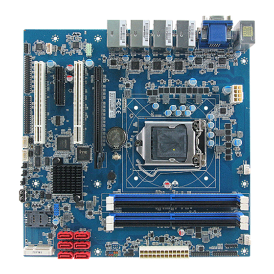
Page 17: Product Overview
User’s Manual 2.1 Product Overview ERX-C236KP User’s Manual 17... -
Page 18: Jumper And Connector List
ERX-C236KP User’s Manual 2.2 Jumper and Connector List You can configure your board to match the needs of your application by setting jumpers. A jumper is the simplest kind of electric switch. It consists of two metal pins and a small metal clip (often protected by a plastic cover) that slides over the pins to connect them. - Page 19 User’s Manual COM1 RS232 connector 5 x 2 wafer, pitch 2.00mm JCOM1A1 COM2 RS232 connector 5 x 2 wafer, pitch 2.00mm JCOM2A1 COM1 RS485/422 connector 3 x 2 header, pitch 2.00 mm JCOM1B1 COM2 RS485/422 connector 3 x 2 header, pitch 2.00 mm JCOM2B1 Serial port 3/4/5/6 connector 20 x 2 header, pitch 2.00mm...
-
Page 20: Setting Jumpers & Connectors
ERX-C236KP User’s Manual 2.3 Setting Jumpers & Connectors 2.3.1 Serial port 1/2 pin9 signal select (JRI1/2) Ring* +12V JRI2 JRI1 * Default 2.3.2 AT/ATX Power Mode Select (JATATX1) ATX* * Default 20 ERX-C236KP User’s Manual... -
Page 21: Clear Cmos (Jcmos1)
User’s Manual 2.3.3 Clear CMOS (JCMOS1) Protect* Clear CMOS * Default 2.3.4 General purpose I/O connector (JDIO1) Signal PIN PIN Signal SMB_CLK_9555 17 18 SMB_DATA_9555 ERX-C236KP User’s Manual 21... -
Page 22: Com1 Rs232 Connector (Jcom1A1)
ERX-C236KP User’s Manual 2.3.5 COM1 RS232 connector (JCOM1A1) Signal PIN PIN Signal NRXDA NDCDA# NDTRA# NTXDA NDSRA# NCTSA# NRTSA# JNRIA# 2.3.6 COM2 RS232 connector (JCOM2A1) Signal PIN PIN Signal NRXDB NDCDB# NDTRB# NTXDB NDSRB# NCTSB# NRTSB# JNRIB# 22 ERX-C236KP User’s Manual... -
Page 23: Com1 Rs485/422 Connector (Jcom1B1)
User’s Manual 2.3.7 COM1 RS485/422 connector (JCOM1B1) Signal PIN PIN Signal 485A_TX- 422A_RX- 485A_TX+ 422A_RX+ 2.3.8 COM2 RS485/422 connector (JCOM2B1) Signal PIN PIN Signal 485B_TX- 422B_RX- 485B_TX+ 422B_RX+ ERX-C236KP User’s Manual 23... -
Page 24: Serial Port 3/4/5/6 Connector (Jcom3-6)
ERX-C236KP User’s Manual 2.3.9 Serial port 3/4/5/6 connector (JCOM3-6) Signal PIN PIN Signal NDCDC# NRXDC NTXDC NDTRC# NDSRC# NRTSC# NCTSC# NRIC# NDCDD# NRXDD NTXDD NDTRD# NDSRD# NRTSD# NCTSD# NRID# NDCDE# NRXDE NTXDE NDTRE# NDSRE# NRTSE# NCTSE# NRIE# NDCDF# NRXDF NTXDF NDTRF# NDSRF# NRTSF#... -
Page 25: Serial Port 7/8/9/10 Connector (Jcom7-10)
User’s Manual 2.3.10 Serial port 7/8/9/10 connector (JCOM7-10) Signal PIN PIN Signal COM_DCD#_7 COM_RXD_7 COM_TXD_7 COM_DTR#_7 COM_DSR#_7 COM_RTS#_7 COM_CTS#_7 COM_RI#_7 COM_DCD#_8 COM_RXD_8 COM_TXD_8 COM_DTR#_8 COM_DSR#_8 COM_RTS#_8 COM_CTS#_8 COM_RI#_8 COM_DCD#_9 COM_RXD_9 COM_TXD_9 COM_DTR#_9 COM_DSR#_9 COM_RTS#_9 COM_CTS#_9 COM_RI#_9 COM_DCD#_10 COM_RXD_10 COM_TXD_10 COM_DTR#_10 COM_DSR#_10 COM_RTS#_10 COM_CTS#_10... -
Page 26: Atx Power Connector (Atxpwr1)
ERX-C236KP User’s Manual 2.3.11 ATX Power connector (ATXPWR1) Signal Signal +3.3V +3.3V +3.3V -12V ATX_PSON# ATX_PWRGD +V5SB +12V +12V +3.3V 2.3.12 ATX 12V power connector (ATX12V1) Signal Signal +12V +12V +12V +12V 26 ERX-C236KP User’s Manual... -
Page 27: Usb 2.0 Connector (Jusb2)
User’s Manual 2.3.13 USB 2.0 connector (JUSB2) Signal Signal USBVCC_BC USBVCC_BC USB_R_DN11 USB_R_DN12 USB_R_DP11 USB_R_DP12 2.3.14 Battery connector (JBAT1) Signal RTC_VBAT_1 ERX-C236KP User’s Manual 27... -
Page 28: Lpc Connector (Jlpc1)
ERX-C236KP User’s Manual 2.3.15 LPC connector (JLPC1) Signal PIN PIN Signal LPC_AD0_R +3.3V LPC_AD1_R BUF_PLT_RST# LPC_AD2_R LPC_FRAME#_R LPC_AD3_R LPC_CLK LPC_SERIRQ_R 2.3.16 Front panel setting connector (JFP1) Signal PIN PIN Signal HDD_LED+ PER_LED+ HDD_LED- PER_LED- RSET_BTN# PWRBTN# 28 ERX-C236KP User’s Manual... -
Page 29: Cpu Fan Connector (Cpufan1)
User’s Manual 2.3.17 CPU fan connector (CPUFAN1) Signal +12V CPUFANIN1 CPUFANOUT1 2.3.18 System fan connector (SYSFAN1) Signal +12V SYSFANIN1 SYSFANOUT1 ERX-C236KP User’s Manual 29... -
Page 30: Smbus Connector (Jsmb1)
ERX-C236KP User’s Manual 2.3.19 SMBus connector (JSMB1) Signal SMB_CLK_MAIN SMB_DATA_MAIN SMB_ALERT#_MAIN +3.3V 2.3.20 PC Buzzer header (JBZ1) Signal HAD_SPKR- 30 ERX-C236KP User’s Manual... -
Page 31: Lpt Connector (Jprt1)
User’s Manual 2.3.21 LPT connector (JPRT1) Signal PIN PIN Signal PT_STB- PT_AFD# PTD0 ERR# PTD1 PT_PAR_INIT# PTD2 PT_SLIN# PTD3 PTD4 PTD5 PTD6 PTD7 ACK# BUSY SLCT 2.3.22 Speaker connector (SPK1) Signal LSPK+ LSPK- RSPK+ RSPK- ERX-C236KP User’s Manual 31... -
Page 32: Front Audio Connector (Faud1)
ERX-C236KP User’s Manual 2.3.23 Front Audio connector (FAUD1) Signal PIN PIN Signal LIEN2_JD LINE2_L MIC2_JD LINE2_R AUD_FRONT_DET MIC2_R MIC2_L 2.3.23.1. Signal Description –Front Audio connector (FAUD1) Signal Signal Description LINE2_JD AUDIO IN (LINE_RIN/LIN)sense pin MIC2_JD MIC IN (MIC_RIN/LIN) sense pin 32 ERX-C236KP User’s Manual... -
Page 33: Sgpio Connector (Jsgpio1) (Option)
User’s Manual (Option) 2.3.24 SGPIO connector (JSGPIO1) Signal PIN PIN Signal SGIO_LOAD SGIO_DATOUT0 SGIO_CLK SGIO_DATOUT1 2.3.25 AT/ATX Power Mode Select (JATAX1) Signal AT_BN PWRBTN# ERX-C236KP User’s Manual 33... -
Page 34: Spi Connector (Jspi1)
ERX-C236KP User’s Manual 2.3.26 SPI connector (JSPI1) Signal Signal +V3.3_SPI SSPI_CS0#_R SSPI_SCLK_R SSPI_SO_R SSPI_SI_R SSPI_HOLD#0 34 ERX-C236KP User’s Manual... -
Page 35: Bios Setup
User’s Manual 3.BIOS Setup ERX-C236KP User’s Manual 35... -
Page 36: Introduction
ERX-C236KP User’s Manual 3.1 Introduction The BIOS setup program allows users to modify the basic system configuration. In this following chapter will describe how to access the BIOS setup program and the configuration options that may be changed. 3.2 Starting Setup The AMI BIOS™... -
Page 37: Using Setup
User’s Manual 3.3 Using Setup In general, you use the arrow keys to highlight items, press <Enter> to select, use the PageUp and PageDown keys to change entries, press <F1> for help and press <Esc> to quit. The following table provides more detail about how to navigate in the Setup program using the keyboard. -
Page 38: Getting Help
ERX-C236KP User’s Manual 3.4 Getting Help Press F1 to pop up a small help window that describes the appropriate keys to use and the possible selections for the highlighted item. To exit the Help Window press <Esc> or the F1 key again. -
Page 39: Bios Setup
User’s Manual 3.6 BIOS setup Once you enter the Aptio Setup Utility, the Main Menu will appear on the screen. The Main Menu allows you to select from several setup functions and exit choices. Use the arrow keys to select among the items and press <Enter> to accept and enter the sub-menu. 3.6.1 Main Menu This section allows you to record some basic hardware configurations in your computer and set the system clock. -
Page 40: System Language
ERX-C236KP User’s Manual 3.6.1.1 System Language Choose the system default language. 3.6.1.2 System Date Set the Date. Use Tab to switch between Date element. 3.6.1.3 System Time Set the Time. Use Tab to switch between Date element. Note: The BIOS setup screens shown in this chapter are for reference purposes only, and may not exactly match what you see on your screen. -
Page 41: Advanced Menu
User’s Manual 3.6.2 Advanced Menu This section allows you to configure your CPU and other system devices for basic operation through the following sub-menus. 3.6.2.1 Trusted Computing Item Options Description Enables or Disables BIOS support for security Disabled device. O.S. will show Srcurity Device.TCG Security Device Support Enabled[Default] EFI protocol and INT1A interface will not be... -
Page 42: Acpi Settings
ERX-C236KP User’s Manual 3.6.2.2 ACPI Settings Item Options Description Enables or Disables System ability to Disabled Hibernate (OS/S4 Sleep State).This option Enable Hibernation Enabled[Default] may not be effective with some operating systems. Suspend Disabled, Select the highest ACPI sleep state the ACPI Sleep State S3 (Suspend to system will enter when the SUSPEND button... -
Page 43: S5 Rtc Wake Settings
User’s Manual 3.6.2.3 S5 RTC Wake Settings Item Options Description Enabled or disable System wake on RTC Disabled[Default], alarm event. Fixed Time: System will wake on Wake system from S5 Fixed Time the hr:::min::sec specified. Dynamic_Time : Dynamic Time System will wake on the cunent time + Increase minute(s). - Page 44 ERX-C236KP User’s Manual Item Options Description Enabled or disable System wake on RTC Disabled, alarm event. Fixed Time: System will wake on Wake system from S5 Fixed Time[Default] the hr:::min::sec specified. Dynamic_Time : Dynamic Time System will wake on the cunent time + Increase minute(s).
-
Page 45: Super Io Configuration
User’s Manual 3.6.2.4 Super IO Configuration Item Description Serial Port 1 Configuration Set Parameters of Serial Port 1 (COMA). Serial Port 2 Configuration Set Parameters of Serial Port 2 (COMB). Serial Port 3 Configuration Set Parameters of Serial Port 3 (COMC). Serial Port 4 Configuration Set Parameters of Serial Port 4 (COMD). -
Page 46: Serial Port 1 Configuration
ERX-C236KP User’s Manual 3.6.2.4.1 Serial Port 1 Configuration Item Option Description Disabled Serial Port Enable or Disable Serial Port(COM) Enabled[Default], RS232[Default], Set COM Port as RS232, RS422, RS485 UART 232 422 485 RS422 mode. RS485 3.6.2.4.2 Serial Port 2 Configuration 46 ERX-C236KP User’s Manual... -
Page 47: Serial Port 3 Configuration
User’s Manual Item Option Description Disabled Serial Port Enable or Disable Serial Port(COM) Enabled[Default], RS232[Default], Set COM Port as RS232, RS422, RS485 UART 232 422 485 RS422 mode. RS485 3.6.2.4.3 Serial Port 3 Configuration Item Option Description Disabled Serial Port Enable or Disable Serial Port(COM) Enabled[Default], ERX-C236KP User’s Manual 47... -
Page 48: Serial Port 4 Configuration
ERX-C236KP User’s Manual 3.6.2.4.4 Serial Port 4 Configuration Item Option Description Disabled Serial Port Enable or Disable Serial Port (COM). Enabled[Default], 3.6.2.4.5 Serial Port 5 Configuration Item Option Description Disabled Enable or Disable Serial Port Serial Port Enabled[Default], (COM). 48 ERX-C236KP User’s Manual... -
Page 49: Serial Port 6 Configuration
User’s Manual 3.6.2.4.6 Serial Port 6 Configuration Item Option Description Disabled Enable or Disable Serial Port Serial Port Enabled[Default], (COM). 3.6.2.4.7 Parallel Port Configuration Item Option Description Disabled Enable or Disable Parallel Parallel Port Enabled[Default], Port (LPT/LPTE). ERX-C236KP User’s Manual 49... -
Page 50: Serial Port 7 Configuration
ERX-C236KP User’s Manual 3.6.2.4.8 Serial Port 7 Configuration Item Option Description Disabled Enable or Disable Serial Port Serial Port Enabled[Default], (COM). 3.6.2.4.9 Serial Port 8 Configuration Item Option Description Disabled Enable or Disable Serial Port Serial Port Enabled[Default], (COM). 50 ERX-C236KP User’s Manual... -
Page 51: Serial Port 9 Configuration
User’s Manual 3.6.2.4.10 Serial Port 9 Configuration Item Option Description Disabled Enable or Disable Serial Port Serial Port Enabled[Default], (COM). 3.6.2.4.11 Serial Port 10 Configuration Item Option Description Disabled Enable or Disable Serial Port Serial Port Enabled[Default], (COM). ERX-C236KP User’s Manual 51... -
Page 52: Nct6106D H/W Monitor
ERX-C236KP User’s Manual 3.6.2.5 NCT6106D H/W Monitor 3.6.2.5.1 Smart Fan Mode Configuration Item Option Description Manual Mode Mode 01 Mode 02 Avalue Smart Fan Mode CPU Fan Mode Mode 03 Select: Mode 01 to Mode 20 Mode 04 Or Manual(No Smart Fan) Mode 05 Mode 06 52 ERX-C236KP User’s Manual... - Page 53 User’s Manual Mode 07 Mode 08 Mode 09 Mode 10 Mode 11 Mode 12 Mode 13 Mode 14 Mode 15 Mode 16 Mode 17 Mode 18 Mode 19[Default] Mode 20 CPU Fan Manual Mode Duty 0~255 Set Fan Duty Manually Manual Mode Mode 01[Default] Mode 02...
-
Page 54: Serial Port Console Redirection
ERX-C236KP User’s Manual *Smart Fan Mode 3.6.2.6 Serial Port Console Redirection Item Options Description Disabled[Default], Console Redirection Console Redirection Enable or Disable Enabled 54 ERX-C236KP User’s Manual... -
Page 55: Com1
User’s Manual 3.6.2.6.1 COM1 Item Options Description Emulation: ANSI: Extended ASCII char set. VT100 VT100: ASCII char set. VT100+: Extends VT100+[Default] Terminal Type VT100 to support color, function keys, etc. VT-UTF8 VT-UTF8: Uses UTF8 encoding to map ANSI Unicode chars onto 1 or more bytes. 9600 19200 Select serial port transmission speed. -
Page 56: Intel Txt Information
ERX-C236KP User’s Manual stop the data flow. Once the buffers are empty, a ‘start’ signal can be sent to re-start the flow. Hardware flow control uses two wires to send start/stop signals. Disabled Enable VT-UTF8 Combination Key Support for VT-UTF8 Combo Key Support Enabled[Default] ANSI/VT100 terminals. -
Page 57: Intel Rc Acpi Settings
User’s Manual 3.6.2.8 Intel RC ACPI Settings Item Options Description Auto[Default], Enabled – OS Controlled ASPM,Disabled Native ASPM Disabled, ASPM Enabled 3.6.2.9 CPU Configuration ERX-C236KP User’s Manual 57... -
Page 58: Cpu - Power Management Control
ERX-C236KP User’s Manual Item Options Description Disabled[Default], Enabled/Disable Software Guard SW Guard Extensions (SGX) Enabled Extensions(SGX) When enabled,a VMM can utilize the Intel (VMX) Virtualization Disabled, additional hardware capabilities provided by Technology Enabled[Default] Vanderpool Technology. All[Default] Number of cores to enable in each processor Active Processor Cores package. - Page 59 User’s Manual Enabled[Default] CPU to go to C states when it’s not 100276052152tilized. Enable/Disable C1E. When enabled, CPU will Disabled, Enhanced C-states switch to minimum speed when all cores enter Enabled[Default] C-State. Disabled, C-State Auto Demotion Configure C-State Auto Demotion. C1 and C3[Default] Disabled, C-State Un-demotion...
-
Page 60: Pch-Fw Configuration
ERX-C236KP User’s Manual 3.6.2.10 PCH-FW Configuration 3.6.2.10.1 OEM Flags Settings Item Options Description OEMFlag Bit 15: Unconfigure ME with resetting MEBx Disabled[Default], Unconfigure ME Enabled password to default. 60 ERX-C236KP User’s Manual... -
Page 61: Firmware Update Configuration
User’s Manual 3.6.2.10.2 Firmware Update Configuration Item Options Description Disabled[Default], Me FW Image Re-Flash Enable/Disable Me FW Image Re-Flash function. Enabled 3.6.2.11 Network Stack Configuration Item Options Description Disabled[Default] Network Stack Enable/Disable UEFI Network Stack. Enabled Ipv4 PXE Support Disabled[Default] Enable/Disable IPv4 PXE boot support. -
Page 62: Csm Configuration
ERX-C236KP User’s Manual Enabled PXE boot support will not be available. Enable/Disable IPv4 HTTP boot support will not be Disabled[Default] Ipv4 HTTP Support Enabled available. Enable/Disable IPv6 PXE boot support. If disabled, IPv6 Disabled[Default] Ipv6 PXE Support Enabled PXE boot support will not be available. Enable/Disable IPv6 HTTP boot support. -
Page 63: Usb Configuration
User’s Manual UEFI only Do not launch[Default] Controls the execution of UEFI and Legacy PXE Network UEFI OpROM. Legacy Do not launch Controls the execution of UEFI and Legacy Storage UEFI Storage OpROM. Legacy[Default] UEFI Controls the execution of UEFI and Legacy Video Video Legacy[Default] OpROM. -
Page 64: Chipset
ERX-C236KP User’s Manual 3.6.3 Chipset 3.6.3.1 System Agent (SA) Configuration Item Option Description Disabled VT-d VT-d capability. Enabled[Default] 64 ERX-C236KP User’s Manual... -
Page 65: Memory Configuration
User’s Manual 3.6.3.1.1 Memory Configuration 3.6.3.1.2 Graphics Configuration Item Option Description Auto[Default] Select which of IGFX/PEG/PCI Graphics device IGFX Primary Display should be Primary Display Or select SG for Switchable Gfx. Auto[Default] Internal Graphics Disabled Keep IGFX enabled based on the setup options. Enabled ERX-C236KP User’s Manual 65... -
Page 66: Dmi/Opi Configuration
ERX-C236KP User’s Manual 3.6.3.1.3 DMI/OPI Configuration 3.6.3.1.4 PEG Port Configuration Item Option Description Disabled Enable Root Port Enabled Enable or Disable Root Port Auto[Default] Auto[Default] Gen1 Max Link Speed Configure PEG 0:1:0 Max Speed Gen2 Gen3 66 ERX-C236KP User’s Manual... -
Page 67: Peg Port Feature Configuration
User’s Manual Auto[Default] Force X1 Force X2 Max Link Width Force PEG link to retrain to X1/2/4/8 Force X4 Force X8 Disabled Auto[Default] Control ASMP support for the PEG0. This ASPM ASPM L0s has no effect if PEG is not the currently ASPM L1 active device. -
Page 68: Pch-Io Configuration
ERX-C236KP User’s Manual 3.6.3.2 PCH-IO Configuration Item Option Description Enabled[Default] PHY LAN Controller Enable/Disable Onboard NIC. Disabled Enabled[Default] Enable/Disable inte grated LAN to wake the Wake on LAN Enable Disabled system. 3.6.3.2.1 PCI Express Configuration 68 ERX-C236KP User’s Manual... -
Page 69: Pci-E Port 5: Lan2(I211At)
User’s Manual 3.6.3.2.1.1. PCI-E Port 5: LAN2(I211AT) Item Option Description Disabled PCI-E Port 5: LAN2(I211AT) Control the PCI Express Root Port. Enabled[Default] 3.6.3.2.1.2. PCI-E Port 6: LAN3(I211AT) ERX-C236KP User’s Manual 69... -
Page 70: Pci-E Port 7: Pci-To-Pci Bridge
ERX-C236KP User’s Manual Item Option Description Disabled PCI-E Port 6: LAN3(I211AT) Control the PCI Express Root Port. Enabled[Default] 3.6.3.2.1.3. PCI-E Port 7: PCI-to-PCI Bridge Item Option Description Disabled PCI-E Port 7: PCI-to-PCI Bridge Control the PCI Express Root Port. Enabled[Default] 70 ERX-C236KP User’s Manual... -
Page 71: Pci-E Port 8: Lan4(I211At)
User’s Manual 3.6.3.2.1.4. PCI-E Port 8: LAN4(I211AT) Item Option Description Disabled PCI-E Port 8: LAN4(I211AT) Control the PCI Express Root Port. Enabled[Default] 3.6.3.2.1.5. PCI-E Port 9: PCI-E x4 Slot ERX-C236KP User’s Manual 71... -
Page 72: Extra Options
ERX-C236KP User’s Manual Item Option Description Enabled[Default] PCI-E Port 9: PCI-E x4 Slot Control the PCI Express Root Port. Disabled Auto L0sL1 Set the ASPM Level : Force L0s-Force all ASPM links to L0a State AUTO – BIOS auto configure DISABLE – Disables ASPM Disabled[Default] Disabled[Default] L1.1... -
Page 73: Pci-E Port 19: Mini Pci-E Slot
User’s Manual 3.6.3.2.1.6. PCI-E Port 19: Mini PCI-E Slot Item Option Description Disabled PCI-E Port 19: Mini PCI-E Slot Control the PCI Express Root Port. Enabled[Default] Auto Set the ASPM Level : Force L0s-Force all ASPM links to L0a State AUTO – BIOS auto L0sL1 configure DISABLE –... -
Page 74: Extra Options
ERX-C236KP User’s Manual 3.6.3.2.1.6.1. Extra options Item Option Detect Non-Compliance Device Disabled Prefetchable Memory Reseved Memory Alignment Prefetchable Memory Alignment PCI-E Max TLP Size 256 Bytes 74 ERX-C236KP User’s Manual... -
Page 75: Sata And Rst Configuration
User’s Manual 3.6.3.2.2 SATA And RST Configuration Item Option Description Enabled[Default], SATA Controller(s) Enable/Disable SATA Device. Disabled AHCI[Default] Determines how SATA controller(s) SATA Mode Selection DAID operate. Default[Default] Gen1 Indicates the maximum speed the SATA SATA Controller Speed Gen2 controller can support. Gen3 Disabled SATA Port... -
Page 76: Software Feature Mask Configuration
ERX-C236KP User’s Manual Hard Disk Drive[Default], Identify the SATA port is connected to Solid SATA Device Type State Drive or Hard Disk Drive. Solid State Drive Disabled SATA6 Port Enable or Disable SATA Port. Enabled[Default], Hard Disk Drive[Default], Identify the SATA port is connected to Solid SATA Device Type State Drive or Hard Disk Drive. -
Page 77: Hd Audio Configuration
User’s Manual 3.6.3.2.3 HD Audio Configuration Item Option Description Control Detection of the HD-Audio device. Disabled Disabled = HDA will be unconditionally disabled HD Audio Enabled Enabled = HDA will be unconditionally enabled Auto[Default], Auto = HDA will be enabled if present, disabled otherwise. -
Page 78: Security
ERX-C236KP User’s Manual 3.6.4. Security Administrator Password Set setup Administrator Password User Password Set User Password 3.6.4.1 Secure Boot 78 ERX-C236KP User’s Manual... -
Page 79: Key Management
User’s Manual Item Option Description Secure Boot activated. When: Secure Boot is Disabled[Default], Secure Boot enabled Platform Key(PK) is enrolled, System mode Enabled is User/Deployed, and CSM is disabled Customizable Secure Boot mode: In Custom mode Secure Boot Standard Secure Boot Policy Variables can be configured by a Customization Custom[Default], physically present user without full authentication... -
Page 80: Boot
ERX-C236KP User’s Manual 3.6.5. Boot Item Option Description Number of seconds to wait for setup activation Setup Prompt Timeout key. 65535(0xFFFF) means indefinite waiting. On[Default] Bootup NumLock State Select the Keyboard NumLock state Disabled[Default] Quiet Boot Enables or disables Quiet Boot option Enabled Boot Option #1 Set the system boot order. -
Page 81: Save And Exit
User’s Manual 3.6.6. Save and exit 3.6.6.1. Save Changes and Reset Reset the system after saving the changes. 3.6.6.2. Discard Changes and Reset Reset system setup without saving any changes. 3.6.6.3. Restore Defaults Restore/Load Default values for all the setup options. 3.6.6.4. -
Page 82: Drivers Installation
ERX-C236KP User’s Manual 4. Drivers Installation Note: Installation procedures and screen shots in this section are for your reference and may not be exactly the same as shown on your screen. 82 ERX-C236KP User’s Manual... -
Page 83: Install Chipset Driver
User’s Manual 4.1 Install Chipset Driver Insert the Supporting DVD-ROM to DVD-ROM drive, and it should show the index page of Avalue’s products automatically. If not, locate Index.htm and choose the product from the menu left. Note: The installation procedures and screen shots in this section are based on Windows 10 operation system. -
Page 84: Install Vga Driver
ERX-C236KP User’s Manual 4.2 Install VGA Driver Insert the Supporting DVD-ROM to DVD-ROM drive, and it should show the index page of Avalue’s products automatically. If not, locate Index.htm and choose the product from the menu left. Note: The installation procedures and screen shots in this section are based on Windows 10 operation system. -
Page 85: Install Sol Driver
User’s Manual 4.3 Install SOL Driver Insert the Supporting CD-ROM to CD-ROM drive, and it should show the index page of Avalue’s products automatically. If not, locate Index.htm and choose the product from the menu left. Note: The installation procedures and screen shots in this section are based on Windows 10 operation system. -
Page 86: Install Audio Driver (For Realtek Alc892 Hd Audio)
ERX-C236KP User’s Manual 4.4 Install Audio Driver (For Realtek ALC892 HD Audio) Insert the Supporting DVD-ROM to DVD-ROM drive, and it should show the index page of Avalue’s products automatically. If not, locate Index.htm and choose the product from the menu left. Note: The installation procedures and screen shots in this section are based on Windows 10 operation... -
Page 87: Install Lan Driver
User’s Manual 4.5 Install LAN Driver Insert the Supporting DVD-ROM to DVD-ROM drive, and it should show the index page of Avalue’s products automatically. If not, locate Index.htm and choose the product from the menu left. Note: The installation procedures and screen shots in this section are based on Windows 10 operation system. - Page 88 ERX-C236KP User’s Manual Step 6. Installing. Step 7. Click Finish to complete setup. 88 ERX-C236KP User’s Manual...
-
Page 89: Install Irst Driver
User’s Manual 4.6 Install IRST Driver Insert the Supporting DVD-ROM to DVD-ROM drive, and it should show the index page of Avalue’s products automatically. If not, locate Index.htm and choose the product from the menu left. Note: The installation procedures and screen shots in this section are based on Windows 10 operation system. - Page 90 ERX-C236KP User’s Manual Step 6. Click Finish to complete setup. 90 ERX-C236KP User’s Manual...
- Page 91 User’s Manual 5. Mechanical Drawing ERX-C236KP User’s Manual 91...
- Page 92 ERX-C236KP User’s Manual Unit: mm 92 ERX-C236KP User’s Manual...
- Page 93 User’s Manual Unit: mm ERX-C236KP User’s Manual 93...
- Page 94 ERX-C236KP User’s Manual 94 ERX-C236KP User’s Manual...
Need help?
Do you have a question about the ERX- C236KP and is the answer not in the manual?
Questions and answers