
Subscribe to Our Youtube Channel
Related Manuals for Avalue Technology RSC-IMX61


Summary of Contents for Avalue Technology RSC-IMX61
- Page 1 RSC-IMX61 Freescale i.MX6 Cortex-A9 User’s Manual Ed – 19 September, 2018 Part No. E2047RSC601R...
- Page 2 Disclaimer Avalue Technology Inc. reserves the right to make changes, without notice, to any product, including circuits and/or software described or contained in this manual in order to improve design and/or performance. Avalue Technology assumes no responsibility or liability for the...
- Page 3 User’s Manual otherwise specified. Applications that are described in this manual are for illustration purposes only. Avalue Technology Inc. makes no representation or warranty that such application will be suitable for the specified use without further testing or modification. Life Support Policy Avalue Technology’s PRODUCTS ARE NOT FOR USE AS CRITICAL COMPONENTS IN...
- Page 4 (such as your sales receipt) in a shippable container. A product returned without proof of the purchase date is not eligible for warranty service. 5. Write the RMA number visibly on the outside of the package and ship it prepaid to your dealer. 4 RSC-IMX61 User’s Manual...
-
Page 5: Table Of Contents
3. Build and install Android image ................. 24 Setup Build Environment ..................25 Download source code and MFG tool ..............25 Compiler Android Source code ................26 Install Android image into eMMC ................27 4. Mechanical Drawing ....................30 RSC-IMX61 User’s Manual 5... -
Page 6: Getting Started
1.2 Packing List Before you begin installing your single board, please make sure that the following materials have been shipped: 1 x RSC-IMX61 Module 1 x Debug cable 6 RSC-IMX61 User’s Manual... -
Page 7: Document Amendment History
User’s Manual 1.3 Document Amendment History Revision Date Comment November 2015 Initial Release September 2018 Update System Specifications RSC-IMX61 User’s Manual 7... -
Page 8: Manual Objectives
We strongly recommend that you study this manual carefully before attempting to interface with RSC-IMX61 series or change the standard configurations. Whilst all the necessary information is available in this manual we would recommend that unless you are confident, you contact your supplier for guidance. -
Page 9: System Specifications
B/L Inverter/Converter Backlight driver control (12V, GND, ENBKL, PWM, 5V) Audio Port Line out (Audio Jack), speaker out & MIC in (wafer) mPCIe socket x 1 (with PCIe & USB2.0 signal) Expansion Slots SD socket x 1 RSC-IMX61 User’s Manual 9... - Page 10 12 ~ 26V DC input, 2.5mm DC Jack, typical 19V input with brownout detection Operating Temperature -20 ~ 85 degree Storage Temperature -40 ~ 85 degree Operating Humidity 0 ~ 90% Dimensions 146mm x 102mm Weight Note: Specifications are subject to change without notice. 10 RSC-IMX61 User’s Manual...
-
Page 11: Architecture Overview - Block Diagram
User’s Manual 1.6 Architecture Overview – Block Diagram The following block diagram shows the architecture and main components of RSC-IMX61. RSC-IMX61 User’s Manual 11... -
Page 12: Hardware Configuration
RSC-IMX61 2. Hardware Configuration 12 RSC-IMX61 User’s Manual... -
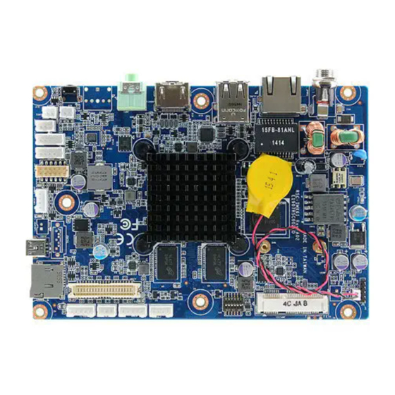
Page 13: Product Overview
User’s Manual 2.1 Product Overview RSC-IMX61 User’s Manual 13... -
Page 14: Jumper And Connector List
4 x 1 wafer, pitch 2.00mm JTOUCH1 Touch Panel connector 4 x 1 wafer, pitch 2.00mm JSPL1 Speaker L connector 2 x 1 wafer, pitch 2.00mm Speaker R connector 2 x 1 wafer, pitch 2.00mm JSPR1 14 RSC-IMX61 User’s Manual... - Page 15 Mini USB connector for Boot/Debug MINI USB-MAB_5P JUSB2 2 x USB2.0 connector JUSB4 USB connector 5 x 1 wafer, pitch 2.00mm JLCD1 LVDS connector 20 x 2 wafer, pitch 1.25mm LCD inverter connector 5 x 1 wafer, pitch 2.00mm JBKLT1 RSC-IMX61 User’s Manual 15...
-
Page 16: Setting Jumpers & Connectors
RSC-IMX61 2.3 Setting Jumpers & Connectors 2.3.1 Boot set selector (SW1) OTG load SD boot eMMC boot Power-in boot choice boot Shutdown 2.3.2 Battery connector (JBAT1) Signal +V_BAT 16 RSC-IMX61 User’s Manual... -
Page 17: Can Bus Connector (Jcan1)
User’s Manual 2.3.3 Can Bus connector (JCAN1) Signal CAN_H CAN_L 2.3.4 Touch Panel connector (JTOUCH1) Signal XP_A YP_A XM_A YM_A RSC-IMX61 User’s Manual 17... -
Page 18: Speaker L Connector (Jspl1)
RSC-IMX61 2.3.5 Speaker L connector (JSPL1) Signal SPKL_N SPKL_P 2.3.6 Speaker R connector (JSPR1) Signal SPKR_N SPKR_P 18 RSC-IMX61 User’s Manual... -
Page 19: Line In, Mic Connector (Jmic1)
User’s Manual 2.3.7 Line In, MIC connector (JMIC1) Signal MIC_DET MIC_IN MIC_GND 2.3.8 Serial ATA connector (JSATA1) Signal RSC-IMX61 User’s Manual 19... -
Page 20: Sata Power Connector (Jsatap1)
RSC-IMX61 2.3.8 SATA power connector (JSATAP1) Signal 2.3.9 Serial Port 1 connector (JCOM1) Signal COM1_TX COM1_RX 20 RSC-IMX61 User’s Manual... -
Page 21: Serial Port 2 Connector (Jcom2)
User’s Manual 2.3.10 Serial Port 2 connector (JCOM2) Signal COM2_TX COM2_RX COM2_RTS COM2_CTS 2.3.11 I2C connector (JI2C1) Signal +3.3V JI2C_SCL JI2C_SDA JI2C_INT# RSC-IMX61 User’s Manual 21... -
Page 22: General Purpose I/O Connector (Jgpio1)
RSC-IMX61 2.3.12 General purpose I/O connector (JGPIO1) Signal Signal GPIO2 GPIO1 GPIO4 GPIO3 GPIO6 GPIO5 GPIO8 GPIO7 GPIO10 GPIO9 +3.3V 2.3.13 USB connector (JUSB4) Signal USB_NP4 USB_PP4 22 RSC-IMX61 User’s Manual... -
Page 23: Lvds Connector (Jlcd1)
Signal +12V +12V LVDS1_CLK_N LVDS0_CLK_N LVDS1_CLK_P LVDS0_CLK_P LVDS1_TX3_N LVDS1_TX2_N LVDS1_TX3_P LVDS1_TX2_P LVDS1_TX1_N LVDS1_TX0_N LVDS1_TX1_P LVDS1_TX0_P LVDS0_TX3_N LVDS0_TX2_N LVDS0_TX3_P LVDS0_TX2_P LVDS0_TX1_N LVDS0_TX0_N LVDS0_TX1_P LVDS0_TX0_P LVDS_DDC_CLK LVDS_DDC_DATA +3.3V +3.3V 2.3.16 LCD inverter connector (JBKLT1) Signal +12V BKLT_EN INV_PWM RSC-IMX61 User’s Manual 23... -
Page 24: Build And Install Android Image
RSC-IMX61 3. Build and install Android image 24 RSC-IMX61 User’s Manual... -
Page 25: Setup Build Environment
Here you can find instruction to setup development environment for Android source code for RSC-IMX61 and the way to install it on eMMC. With this guideline, user will be able to setup the system easily and test all the functions with the system. -
Page 26: Compiler Android Source Code
Recovery image file for Quad core system.img System image file recovery.img Recovery image file u-boot-imx6dl.imx Bootloader for 1G Dual Lite u-boot-imx6dl2g.imx Bootloader for 2 G Dual Lite u-boot-imx6q.imx Bootloader for Quad core Please copy all of them to path RSC-IMX61-6.0.1\Image\RSC-IMX6\android\6.0.1\Factory 26 RSC-IMX61 User’s Manual... -
Page 27: Install Android Image Into Emmc
User’s Manual 3.4 Install Android image into eMMC Connect RSC-IMX61 to computer through JUSB1 by mini USB. RSC-IMX61 User’s Manual 27... - Page 28 RSC-IMX61 Set the jumper to OTG mode. Execute “MFG-Helper.exe”. Select the items as the blow picture and click “Run MFG-Tools”. When MFG tool show “HID-compliant device”, click “Start” to start to flash image. 28 RSC-IMX61 User’s Manual...
- Page 29 User’s Manual When it show “Done”, click “Stop” and “Exit” to finish. Turn off the power. Set the jumper to “eMMC boot” and power on to boot Android. RSC-IMX61 User’s Manual 29...
-
Page 30: Mechanical Drawing
RSC-IMX61 4. Mechanical Drawing 30 RSC-IMX61 User’s Manual... - Page 31 User’s Manual Unit: mm RSC-IMX61 User’s Manual 31...
- Page 32 RSC-IMX61 Unit: mm 32 RSC-IMX61 User’s Manual...
Need help?
Do you have a question about the RSC-IMX61 and is the answer not in the manual?
Questions and answers