Table of Contents
Advertisement
Quick Links
ELC-PH12NNDT
Instruction Sheet
Logic Controller with Special Pulse
Input/Output Function
WARNING
•
This Instruction Sheet only provides descriptions for electrical specifications, general specifications,
installation & wiring, troubleshooting and peripherals. Other detail infromation about programming and
commands is compatible with ELC-PC/PA/PH series; please see ELC Application Manual. For more
information about the optional peripherals , please see individual product manual.
•
This is an OPEN TYPE Controller. The ELC should be kept in an enclosure away from airborne dust, humidity,
electric shock risk and vibration. Also, it is equipped with protective methods such as some special tools or
keys to open the enclosure, so as to avoid the hazard to users and the damage to the ELC.
•
Never connect the AC main circuit power supply to any of the input/output terminals, as it will damage the
ELC. Check all the wiring prior to power up. To avoid any electromagnetic noise, make sure the ELC is
properly grounded
. Do NOT touch terminals when power on.
•
Battery replacement: use UL component type: TDRTL-2150/S lithium battery. Refer to following table for
battery life. (NOTE: RTC should be reset after changing battery).
Temperature (°C)
0
25
50
70
Life (Years)
9
8
6
5
Precision of calendar timer:
At 0°C/32°F, less than –117 seconds error per month.
At 25°C/77°F, less than 52 seconds error per month.
At 55°C/131°F, less than –132 seconds error per month.
•
Warning – Do not disconnect while circuit is live unless area is known to be non-hazardous.
•
Power, input and output (I/O) wiring must be in accordance with Class 1, Div. 2 wiring methods -–Article
501-10(B)(1) of the National Electrical Code.
•
Suitable for use in Class 1, Division 2, Groups A, B, C, D or Non-Hazardous locations only.
•
Warning – Explosion hazard – Substitution of components may impair suitability for Class 1, Division 2.
•
Warning – Explosion hazard – Do not disconnect equipment unless power has been switched off or the area
is known to be Non-Hazardous.
INTRODUCTION
1
5.1 Model Name Explanation and Peripherals
Thank you for choosing Eaton Logic Controller (ELC) series products. The ELC-PH series has a 12-points (8 input
points + 4 outputs) MPU with powerful instructions (the same instruction sets as PC/PA series) for use. It also has
an 8K Steps program memory and high-speed pulse inputs(X10 and X11)/outputs (Y10 and Y11). For high-speed
pulse, total bandwidth can up to 130KHz and 100KHz maximum for single input/output. Besides, it also provides
instructions of position control and zero point return to use with high-speed pulse output.
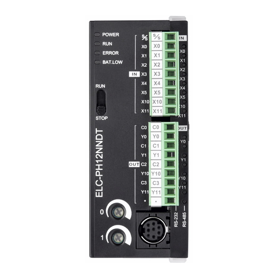
5.2 Product Profile and Outline
POWER
RUN
ERROR
RUN
Y0
C1
Y1
C2
Y2
Y3
Unit: mm
Warning: Battery replacement: Please change the battery within 3
minutes, or the internal data of the ELC (including the program area,
perpetual calendar and latched registers) could be lost or destroyed.
2007-05-08
5011632305-PH05
2
Items
Control Method
I/O Processing Method
Execution Speed
Program Language
Program Capacity
Instructions
X External Input Relay
External Output
Y
Relay
General
Aux.
M
Latched
Relay
Special
100ms
T
Timer
10ms
1ms
16-bit
32-bit
C Counter
32bit
High-speed
Initial
Zero
Step
Return
S
point
General
Latched
Alarm
Current Value of the
T
Timer
Current Value of the
C
Counter
General
Data
Latched
Status indicators of POWER, RUN,
D
Register
1
ERROR and BAT.LOW
Special
Index
2 RUN/STOP switch
VR0: Start-up by M1178/D1178
File Register
3
Corresponding value
For Master Control
VR1: Start-up by M1179/D1179
N
4
Nested Loop
Corresponding value
For CJ, CALL
5 DIN rail clip
P
Instructions
6 I/O terminals
Input Interrupt
7 I/O point indicators
8 COM1 (RS-232) (Rx) indicator
Timer Interrupt
I
9 COM2 (RS-485) (Tx) indicator
High-speed
10 COM1 (RS-232) port
Counter
11 Nameplate
Communication
Extension port for wire to connect
12
extension module/unit
Communication Port in
13 Mounting hole
Series (program read/write)
14 DIN rail track (35mm)
15 Extension unit clip
RS-485 communication port
16
(Master/Slave)
17 DC Power input
2 pin removable terminal (standard
18
accessory)
Power input cable (standard
19
accessory)
20 Battery cover
21 Battery socket connection
22 Battery holder
FUNCTION SPECIFICATIONS
Specifications
Remarks
Stored program, cyclic scan system
I/O refresh instruction is
Batch processing method (when END instruction is
executed)
available
Application Instructions
Basic instructions (several us)
(10~hundreds us)
Including the Step
Instructions + Ladder Logic + SFC
instructions
7,920 STEPS
SRAM+ Battery
32 Basic sequential instructions (including step
168 Application
instructions)
instructions
Correspond to external
X0~X177 in octal, 128 points in decimal
Total
input point
256
Correspond to external
Y0~Y177 in octal, 128 points in decimal
points
output point
M0~M511, 512 points (*1)
Total
M512~M999, 488 points (*3)
Contacts can switch to
4,096
M2000~M4095, 2,096 points (*3)
On/Off in program
points
M1000~M1999, 1,000 points (some are latched)
T0~T199, 200 points (*1)
When the timer that set
T192~T199 for Subroutine
Total
by TMR instruction
T250~T255, 6 points Accumulative (*4)
256
reaches the preset value,
T200~T239, 40 points (*1)
points
the T contact with the
T240~T245, 6 points Accumulative (*4)
same number will be On.
T246~T249, 4 points Accumulative (*4)
C0~C95, 96 points (*1)
When the counter that set
by CNT (DCNT)
C96~C199, 104 points (*3)
C200~C215, 16 points (*1)
instruction reaches the
preset value, the C
C216~C234, 19 points (*3)
Total
contact with the same
C235~C240, 1-phase 1 input, 6 inputs (*3)
253
number will be On.
C243, C245, 1-phase 1 input, 2 points (*3)
points
1-phase high-speed
C246~C249, 1-phase 2 inputs, 3 points (*3)
counter: 20KHz max.
C250, 1-phase 2 inputs, 1 point (*3)
AB-phase high-speed
C251~C254, 2-phase 2 inputs, 3 points (*3)
counter: 4KHz max.
S0~S9, 10 points (*1)
Usage device of step
S10~S19, 10 points, (use with IST instruction)
Total
ladder diagram (SFC)
(*1)
1,024
Latched Range:
S20~S511, 492 points (*1)
points
Start: D1214 (K512)
S512~S895, 384 points (*3)
End: D1215 (K895)
S896~S1023, 124 points (*3)
When the timer reaches
the preset value, the
T0~T255, 256 points
contact of timer will be
On.
When the counter
C0~C199, 16-bit counter, 200 points
reaches the preset value,
C200~C254, 32-bit counter, 50 points
the contact of counter will
be On.
D0~D199, 200 points (*1)
Can be memory area for
D200~D999, 800 points (*3)
Total
storing data. E and F can
D2000~D4999, 3,000 points (*3)
5,000
be used as the special
D1000~D1999, 1,000 points
points
purpose of index
indication.
E0~E3, F0~F3, 8 points (*1)
Extension register to
0~1,599(1,600 points) (*4)
store data.
Control point of master
N0~N7, 8 points
control nested loop
The location point of CJ,
P0~P255, 256 points
CALL.
I001 (X0), I101 (X1), I201 (X2), I301 (X3), I401 (X4),
I501 (X5); 6 points (all are rising-edge trigger)
I6□□(1ms), 7□□(1ms), (□□=01~99ms)
The location pointer of
interrupt subroutine
I010, I020, I030, I040, I050, I060, 6 points
I150, 1 point
COM1: only for slave, ASCII/RTU are available, 115,200 bps max.
COM2: can be Maser/Slave, ASCII/RTU are available, 115,200 bps max.
COM1and COM2 can be used simultaneously
Potentiometer / RTC
MPU built-in 2 points VR / MPU built-in RTC
Items
Specifications
1-phase 1 input: inputs X10 (C243) and X11 (C245). Input frequency can up to
High-speed Counter
100KHz. 1-phase 2 inputs: inputs (X10, X11) C250. Input frequency can up to
100KHz.
High-speed pulse outputs Y10 and Y11. Output frequency can up to 100KHz. It can
Position Control
be used as position control of servo drive or step drive when using with position
instructions (DDRVI and DDRVA) and DZRN (zero point return).
*1: The non-latched area is fixed, and can't be changed.
*2: The non-latched area can be changed to a latched area with parameter setting.
*3: The latched area can be changed to a non-latched area with parameter setting.
*4: The latched area is fixed, and can't be changed.
General
Latched
Special auxiliary relay
M0~M511
M512~M999
M1000~M1999
M
Auxiliary
Latched (default)
Some are latched and
Relay
Non-latched (fixed)
Start: D1200 (K512)
can't be changed
End: D1201 (K999)
100 ms
10 ms
T
T0 ~T199
T200~T239
T240~T245
Timer
Non-latched (fixed)
Non-latched (fixed)
16-bit count up
32-bit count up/down
C
C0~C95
C96~C199
C200~C215
C216~C234
Counter
Latched (default)
Latched (default)
Non-latched
Non-latched
Start: D1208 (K96)
Start: D1210 (K216)
(fixed)
(fixed)
End: D1209 (K199)
End: D1211 (K234)
For general Latched Special register
Latched
S0~S9
S10~S19
S20~S511
S512~S895
S
Factory setting is latched
Step relay
(
Start: D1214 K512
It is fixed to be non-latched
(
End: D1215 K895
General
Latched
Special registers
D0~D199
D200~D999
D1000~D1999
D
Factory setting is latched.
Register
Some are latched and
Non-latched (fixed)
Start: D1216 (K200)
can't be changed.
End: D1217 (K999)
File Register
K0~K1,599, Latched (fixed)
ELECTRICAL SPECIFICATIONS
3
Model
ELC-PH12NNDT
Item
MPU: 24VDC (-15%~20%) (With DC input reverse polarity protection),
Power Supply Voltage
Extension Unit: supplied by the MPU
Fuse
2A
Power Consumption
4W MAX
5 MΩ and above at 500 VDC (Between all inputs / outputs and earth)
Insulation Resistance
ESD: 8KV Air Discharge
Noise Immunity
EFT: Power Line: 2KV, Digital I/O: 1KV, Analog & Communication I/O: 250V
RS: 26MHz~1GHz, 10V/m
The diameter of grounding wire cannot be smaller than the wire diameter of
Grounding
terminals 24V and 0V (All ELC units should be grounded directly to the ground
pole).
Operation: 0℃~55℃ (Temperature), 50~95% (Humidity), Pollution degree 2;
Environment
Storage: -25℃~70℃ (Temperature), 5~95% (Humidity)
UL508
UL1604, Class1,Div2 Operating temperature code: T5
Agency Approvals
European community EMC Directive 89/336/EEC and Low Voltage Directive
73/23/EEC
Standard: IEC61131-2, IEC 68-2-6 (TEST Fc) / IEC61131-2 & IEC 68-2-27 (TEST
Vibration / Shock Resistance
Ea)
Weight (approx.) (g)
158
Input Specifications
Input Type
Photo coupler Isolation
Output Type
Input Current
24VDC 5mA
Rated Current
Voltage Specification
X0,X1,X10,X11:
Off→On, 18.5VDC and above
Max. Inductive Load
Active Level
X2~X5:
Output
Internal
Off→On, 16.5VDC and above
Protection
Outside
X0~X11: On→Off, below 8VDC
Maximum Loading
10ms or 0~20ms
X0~X5
(Setting by D1020)
Response Time
Response Time
X10, X11 The constant of filter
IL05003015E.pdf
Latched
M2000~M4095
Latched (default)
Start: D1202 (K2,000)
End: D1203 (K4,095)
10ms
1 ms
100 ms
T246~T249
T250~T255
Accumulative Latched (fixed)
32-bit high-speed count
up/down
C235~C245
C246~C255
Latched (default)
Start: D1212 (K235)
End: D1213 (K255)
For general
S896~S1023
)
It is fixed to be latched
)
Latched
D2000~D4999
Factory setting is
latched.
Start: D1218 (K2,000)
End: D1219 (K4,999)
Output Specifications
Transistor
0.3A/1 point @ 40℃(Room
Temp.)
5~30VDC
7.2W/24V
None
Rated value according to the load
Y0, Y1
9W / 1 point
Y10, Y11
0.9W / 1 point
<20us
Off→On
<1us (Y10, Y11 only)
Advertisement
Table of Contents

Related Manuals for Eaton ELC-PH12NNDT


Summary of Contents for Eaton ELC-PH12NNDT
- Page 1 When the timer reaches The diameter of grounding wire cannot be smaller than the wire diameter of Thank you for choosing Eaton Logic Controller (ELC) series products. The ELC-PH series has a 12-points (8 input Current Value of the the preset value, the...
- Page 2 ELC. Also, the ELC could connect with the 20.4V~28.8V DC Input Type ELC-PH12NNDT through specific transmission wire to execute the program transmission, the ELC control and the program monitoring. DC/DC TROUBLESHOOTING Judge the errors by the indicators on the front panel.
- Page 3 IL05003015E.pdf exceeded the time-out setting (set by D1000). Please turn the ELC RUN/STOP switch to STOP, and find out the address of the time-out program by special data register D1008. ”WDT” command can be used to solve the problem. ☼ “BAT.LOW”...
Need help?
Do you have a question about the ELC-PH12NNDT and is the answer not in the manual?
Questions and answers