Sign In
Upload
Download
Table of Contents
Contents
Add to my manuals
Delete from my manuals
Share
URL of this page:
HTML Link:
Bookmark this page
Add
Manual will be automatically added to "My Manuals"
Print this page
×
Bookmark added
×
Added to my manuals
Manuals
Brands
Eaton Manuals
Controller
ELC Series
Instruction sheet
Eaton ELC Series Instruction Sheet
Programmable logic controllers
Hide thumbs
Also See for ELC Series
:
Operation manual
(336 pages)
,
Instruction sheet
(11 pages)
1
2
3
4
5
6
7
8
9
10
11
12
Table Of Contents
13
page
of
13
Go
/
13
Contents
Table of Contents
Bookmarks
Advertisement
Table of Contents
1
Product Profile & Outline
2
Specifications
3
Electrical Specifications
4
Installation and Wiring
5
Power Input Wiring
6
Input Point Wiring
7
Trial Run
Download this manual
2014-10-30
5011670405-PVT5
ELC/ELC2 Series
Programmable Logic Controllers
INSTRUCTION SHEET
[Applicable Controllers]
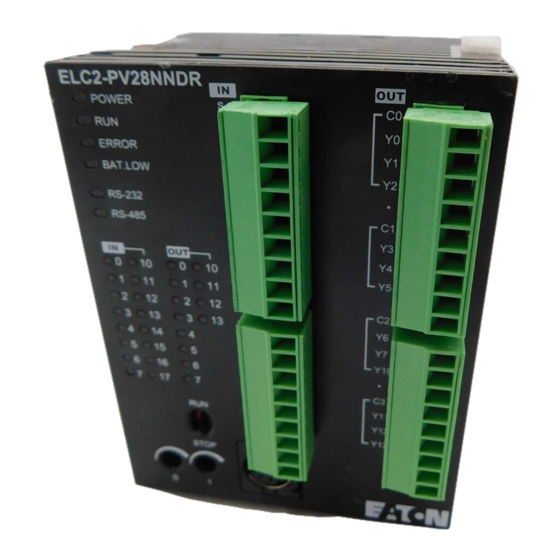
ELC-PV28NNDR
ELC-PV28NNDT
ELC2-PV28NNDR
ELC2-PV28NNDT
ELC2-PV28NNDP
IL050006EN
Table of
Contents
Previous
Page
Next
Page
1
2
3
4
5
Advertisement
Table of Contents
Need help?
Do you have a question about the ELC Series and is the answer not in the manual?
Ask a question
Questions and answers
Related Manuals for Eaton ELC Series
Controller Eaton ELCM Series Operation Manual
Logic controller (336 pages)
I/O Systems Eaton ELC Series Instruction Sheet
Logic controller ethernet distributed i/o adapter module (11 pages)
Controller Eaton ELC2 Series Instruction Sheet
Programmable logic controllers (11 pages)
Controller Eaton ELC2 Series Instruction Sheet
Programmable logic controllers (10 pages)
Controller Eaton ELCM Series Instruction Sheet
Logic controller (10 pages)
Controller Eaton ELCM Series Instruction Sheet
Logic controller (14 pages)
Controller Eaton ELCB Series Instruction Sheet
Logic controller (9 pages)
Controller Eaton Cutler-Hammer ELC Series Basic Training Manual
(22 pages)
Controller Eaton ELC-PC12NNDR Instruction Sheet
Logic controller with multi-function, multiple commands (3 pages)
Controller Eaton ELC-PA10AADR Instruction Sheet
Logic controller with built-in analog input/output (2 pages)
Controller Eaton ELC-PC12NNDR/T Instruction Sheet
Logic controller with multi-function, multiple commands (7 pages)
Controller Eaton ELC-PH12NNDT Instruction Sheet
Logic controller with special pulse input/output function (3 pages)
Controller Eaton ELCM TC Series Instruction Sheet
Logic controller, temperature modules (10 pages)
Controller Eaton ELC2-PV28NNDR Instruction Sheet
Programmable logic controllers (13 pages)
Controller Eaton ELC-CODNET Instruction Manual
Eaton logic controller devicenet (30 pages)
Controller Eaton ELC-PB Programming Manual
Logic controllers (728 pages)
This manual is also suitable for:
Elc2 series
Elc-pv28nndr
Elc-pv28nndt
Elc2-pv28nndr
Elc2-pv28nndt
Elc2-pv28nndp
Table of Contents
Print
Rename the bookmark
Delete bookmark?
Delete from my manuals?
Login
Sign In
OR
Sign in with Facebook
Sign in with Google
Upload manual
Upload from disk
Upload from URL


Need help?
Do you have a question about the ELC Series and is the answer not in the manual?
Questions and answers