Eaton ELCM Series Instruction Sheet
Logic controller
Hide thumbs
Also See for ELCM Series:
- Operation manual (336 pages) ,
- Instruction sheet (9 pages) ,
- Instruction sheet (14 pages)
Table of Contents
Advertisement
Quick Links
Eaton Logic Controller
ELCM Digital Input Output Modules
INSTRUCTION SHEET
[Applicable Digital I/O modules]
ELCM-EX08NNDN
ELCM-EX08NNDR
ELCM-EX08NNDT
ELCM-EX08NNNR
ELCM-EX08NNNT
ELCM-EX16NNDN
ELCM-EX16NNDR
ELCM-EX16NNDT
ELCM-EX16NNNR
ELCM-EX16NNNT
2010-12-10
5011699101-MEX1
IL05004004E
002-1301120-02
Advertisement
Table of Contents

Related Manuals for Eaton ELCM Series


Summary of Contents for Eaton ELCM Series
- Page 1 2010-12-10 5011699101-MEX1 Eaton Logic Controller ELCM Digital Input Output Modules INSTRUCTION SHEET [Applicable Digital I/O modules] ELCM-EX08NNDN ELCM-EX08NNDR ELCM-EX08NNDT ELCM-EX08NNNR ELCM-EX08NNNT ELCM-EX16NNDN ELCM-EX16NNDR ELCM-EX16NNDT ELCM-EX16NNNR ELCM-EX16NNNT IL05004004E 002-1301120-02...
- Page 2 This instruction sheet provides only information on the electrical specification, general functions, installation and wiring. It should be read and understood before attempting to install or use the modules. Further information can be found in the ELC series Programming Manual.
-
Page 3: Digital Input/Output Modules
61.5 Unit: mm EX08 EX08 EX08 EX16 EX16 EX16 ELCM- NNDN NND NNN NNDN NND NNN Type Digital Input/Output Modules Input Output ELCM- Power input Points Type Points Type EX08NNDN EX08NNDR Relay Supplied by bus EX08NNDT Transistor - sink power from EX08NNNR Relay... - Page 4 ELCM- EX08 EX08 EX08 EX16 EX16 EX16 Item NNDN NND NNN NNDN NND NNN Power supply Power reverse protection protection 1,350VAC (Primary-secondary) Voltage 1,350VAC (Primary-PE) withstand 500VDC (Secondary-PE) Insulation > 5MΩ at 500VDC (between all I/O points and ground) resistance ESD: 8KV Air Discharge Noise immunity EFT: Power Line: 2KV, Digital I/O: 1KV...
-
Page 5: Installation
#3: See life curves (below) 120VAC Resistive 3,000 30VDC Inductive(t=7ms) 2,000 240VAC Inductive(cos 0.4) ψ 1,000 120VAC Inductive(cos =0.4) ψ 30VDC Inductive (t=40ms) 0.7 1 Con tact C urren t(A) Installation Please install the ELCM in an enclosure with sufficient space around it to allow heat dissipation, as shown in the figure. -
Page 6: Power Supply
example below. 1. When using controllers with fewer than 32 points, the first expansion input address will start at X20. The first expansion output address will start at Y20. Please refer to the following example for more details: System application example 1: EXT1 EXT2 EXT3 System... -
Page 7: I/O Point Wiring
and actions of any device could influence each other, i.e. breakdown of the entire auto-control system. Therefore, we suggest you wire a protection circuit at the power supply input terminal. See the figure below. ○ ○ AC Power supply: 100 ~ 240VAC, 50/60Hz Breaker ○... - Page 8 Relay (R) output circuit wiring ○ ○ DC power supply Emergency stop: Used an external switch ○ Fuse: Use 5 ~ 10A fuse at the shared terminal of output contacts to protect the output circuit ○ Transient voltage suppressor: To extend the life span of relay contacts. Diode suppression of DC load: Used for smaller loads.
- Page 9 ○ Suppressor: To reduce the interference on AC load. Transistor (T) output circuit wiring ○ ○ ○ DC power supply Emergency stop Circuit protection fuse ○ The output of the transistor is “open collector”. Diode suppression: Used for smaller loads. Diode + Zener suppression: Used for larger loads and for rapidly switching application.
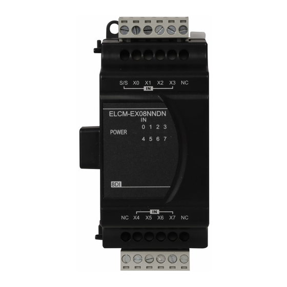
- Page 10 I/O Terminal Layouts ELCM-EX08NNDN ELCM-EX08NNDN (8DI) ELCM-EX08NNNR/T ELCM-EX08NNNR (8DO) ELCM-EX08NNNT (8DO) ELCM-EX08NNDR/T ELCM-EX08NNDR (4DI/4DO) ELCM-EX08NNDT (4DI/4DO) ELCM-EX16NNDN ELCM-EX16NNDN (16DI) ELCM-EX16NNNR/T ELCM-EX16NNNR (16DO) ELCM-EX16NNNT (16DO) ELCM-EX16NNDR/T ELCM-EX16NNDR (8DI/8DO) ELCM-EX16NNDT (8DI/8DO) - 9 -...
Need help?
Do you have a question about the ELCM Series and is the answer not in the manual?
Questions and answers