Table of Contents
Advertisement
Quick Links
ELC-PC12NNDR/T
ELC-PC12NNAR
Logic Controller with Multi-Function,
Multiple Commands
This Instruction Sheet only provides descriptions for electrical specifications, general specifications,
installation & wiring, troubleshooting and peripherals. Other detail infromation about programming and
commands is compatible with ELC-PC/PA/PH series; please see ELC Application Manual. For more
information about the optional peripherals , please see individual product manual.
This is an OPEN TYPE Controller. The ELC should be kept in an enclosure away from airborne dust, humidity,
electric shock risk and vibration. Also, it is equipped with protective methods such as some special tools or
keys to open the enclosure, so as to avoid the hazard to users and the damage to the ELC.
Never connect the AC main circuit power supply to any of the input/output terminals, as it will damage the
ELC. Check all the wiring prior to power up. To avoid any electromagnetic noise, make sure the ELC is
properly grounded
. Do NOT touch terminals when power on.
Battery replacement: use UL component type: TDRTL-2150/S lithium battery. Refer to following table for
battery life. (NOTE: RTC should be reset after changing battery).
Temperature(( C)
0
Life(Years)
9
Precision of calendar timer:
At 0 C/32 F, less than –117 seconds error per month.
At 25 C/77 F, less than 52 seconds error per month.
At 55 C/131 F, less than –132 seconds error per month.
Warning – Do not disconnect while circuit is live unless area is known to be non-hazardous.
Power, input and output (I/O) wiring must be in accordance with Class 1, Div. 2 wiring methods - Article
501-10(B)(1) of the National Electrical Code.
Suitable for use in Class 1, Division 2, Groups A, B, C, D or Non-Hazardous locations only.
Warning – Explosion hazard - Substitution of components may impair suitability for Class 1, Division 2.
Warning – Wxplosion hazard - Do not disconnect equipment unless power has been switched off or the area
is known to be Non-Hazardous.
1
1.1 Model Name Explanation and Peripherals
Thank you for choosing Eaton Logic Controller (ELC) series products. The ELC-PC series has a 12-points (8 input
points + 4 outputs) ELC main processing unit with multiple commands for use. It also has an 8K Steps program
memory to connect to every ELC-PC series expansion unit, including digital I/O (Maximum 128 Inpus / 128 Outputs
expansion points), analog module, etc. for various applications.
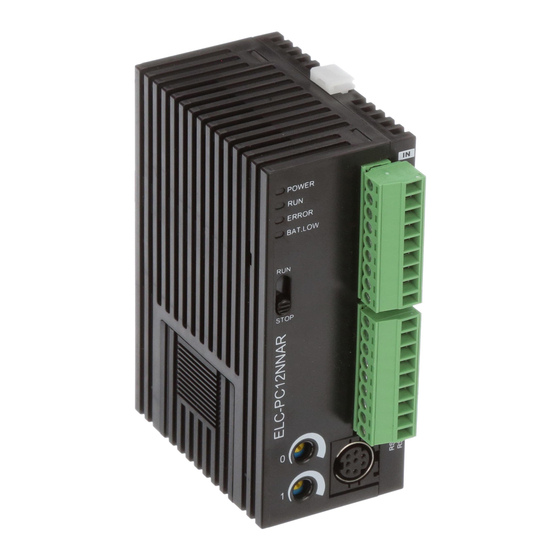
1.2 Product Profile and Outline
POWER
RUN
ERROR
RUN
Y0
C1
Y1
C2
Y2
Y3
Unit: mm
Warning: Battery replacement: Please change the battery within 3
minutes, or the internal data of the ELC (including the program area,
perpetual calendar and latched registers) could be lost or destroyed.
Instruction Sheet
WARNING
25
50
70
8
6
5
INTRODUCTION
1 Status indicator: POWER, RUN,
ERROR, BAT.LOW
2 RUN/STOP switch
3 VR0: M1178 Start-up/D1178
Corresponding value
4 VR1: M1179 Start-up/D1179
corresponding value
5 DIN rail clip
6 I/O terminals
7 I/O point indicators
8 COM1 (RS-232) (Rx) indicator
9 COM2 (RS-485) (Tx) indicator
10 COM1 (RS-232) programming port
11 Nameplate
12 Expansion port
13 Mounting hold of the expansion unit
2007-05-08
5011630506-C206
Advertisement
Table of Contents

Related Manuals for Eaton ELC-PC12NNDR/T


Summary of Contents for Eaton ELC-PC12NNDR/T
- Page 1 1.1 Model Name Explanation and Peripherals Thank you for choosing Eaton Logic Controller (ELC) series products. The ELC-PC series has a 12-points (8 input points + 4 outputs) ELC main processing unit with multiple commands for use. It also has an 8K Steps program memory to connect to every ELC-PC series expansion unit, including digital I/O (Maximum 128 Inpus / 128 Outputs expansion points), analog module, etc.
- Page 2 14 DIN rail (35mm) 15 Expansion unit clip 16 COM2 (RS-485) Communication port 17 DC Power input 18 2 pin removable terminal (standard accessory) 19 Power input cable (standard accessory) 20 Battery Cover 21 Battery socket connection 22 Battery mount FUNCTION SPECIFICATIONS Items Specifications...
- Page 3 Initial value Unchanged Unchanged D, Index register value File register Unchanged ELECTRICAL SPECIFICATIONS Model ELC-PC12NNDR/T ELC-PC12NNAR Item ELC: 24VDC (-15%~+20%) (With DC input reverse polarity protection), Power Supply Voltage Expansion Unit: supplied by the ELC Fuse 2A / 250VAC Power Consumption 3.5W MAX...
- Page 4 Responding Time Adjustable 0~20ms, Default10ms, selected through D1020) AC Input Point Electrical Specification Rated Input Voltage 100 to 120 VAC (-15%~+10%) Maximum Input Current Less than 20 mA Minimum ON Voltage 80 VAC Maximum OFF Voltage 30 VAC Output Point Electrical Specification Output Type Relay-R Transistor-T...
- Page 5 “Function Specifications” for their specifications. LOAD 2. Please watch out the connection of common terminals whilewire the POWER outputs. For example, when wiring ELC-PC12NNDR/T,output terminal Y0 uses one common terminal C0, Y1 uses C1, and Y2~Y3 share C2, as shown below: RELAY...
- Page 6 The ELC-HHP handheld programming panel and the ELCSoft (Windows version) editing program of the ladder diagram are both good for use with the ELC. Also, the ELC could connect with the ELC-PC12NNDR/T,ELC-PC12NNAR through specific transmission wire to execute the program transmission, the ELC control and the program monitoring.
Need help?
Do you have a question about the ELC-PC12NNDR/T and is the answer not in the manual?
Questions and answers