Table of Contents

Related Manuals for Eaton ELCB Series


Summary of Contents for Eaton ELCB Series
- Page 1 2010-12-10 5011699201-PBB1 Eaton Logic Controller ELCB Controllers INSTRUCTION SHEET [Applicable Controllers] ELCB-PB10NNDR/T ELCB-PB14NNDR/T ELCB-PB20NNDR/T ELCB-PB30NNDR/T ELCB-PB40NNDR/T IL05001005E 002-1310020-02...
-
Page 2: Product Profile
Thank you for choosing this Eaton Logic Controller (ELC) series has controllers with 10 to 40 embedded I/O points. To ensure proper installation, operation and maintenance, please read this instruction sheet carefully before installing ELCB-PB. This instruction sheet provides only information on the electrical specification, general functions, installation and wiring. -
Page 3: Electrical Specifications
48.5 Unit: mm Electrical Specifications ELCB- PB10 PB14 PB20 PB30 PB40 NNDR/T NNDR/T NNDR/T NNDR/T NNDR/T Item Power supply 100 ~ 240VAC (-15% ~ 10%), 50/60Hz 5% voltage ELCB-PB starts to run when the power supply rises to 95 ~ 100VAC Operation and stops when the power supply drops to 70VAC. -
Page 4: Installation
Input Points Input No. X0, X1 X2 ~ Input point type Digital input Input type DC (SINK or SOURCE) Input current 24VDC, 5mA Off → On > 15VDC Action level On → Off < 5VDC Off → On 25us 50us Response time On →... -
Page 5: Power Supply
To secure your controller to the DIN rail, pull the clip down, place it onto the rail and gently push the clip up. To remove the ELCB, pull the retaining clip down with a flat screwdriver and gently remove the ELCB from DIN rail. - Page 6 ○ ○ AC power supply:100 ~ 240VAC, 50/60Hz Breaker ○ Emergency stop: This button cuts off the system power supply when accidental emergency takes place. ○ ○ Power indicator AC power supply load ○ ○ Power supply circuit protection fuse (2A) ELCB (main processing unit) ○...
- Page 7 ○ ○ DC power supply Emergency stop: Use an external switch ○ Fuse: Use 5 to 10A fuse at the shared terminal of output contacts to protect the output circuit ○ Transient voltage suppressor: To extend the life span of relay contacts. 1.
- Page 8 ○ ○ ○ DC power supply Emergency stop Circuit protection fuse ○ The output of the transistor module is “open collector”. If Y0/Y1 is set to pulse output, the output current has to be 0.05 ~ 0.5A to ensure normal operation of the output.
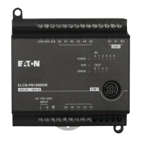
- Page 9 I/O terminal layout ELCB-PB10NNDR/T +24V ELCB-PB10NNDR (6DI-DC/4DO-R) +24V ELCB-PB10NNDT (6DI-DC/4DO-T) ELCB-PB14NNDR/T +24V ELCB-PB14NNDR (8DI-DC/6DO-R) +24V ELCB-PB14NNDT (8DI-DC/6DO-T) ELCB-PB20NNDR +24V ELCB-PB20NNDR (12DI-DC/8DO-R) +24V ELCB-PB20NNDT (12DI-DC/8DO-T) ELCB-PB30NNDR +24V ELCB-PB30NNDR (18DI-DC/12DO-R) C2 Y10 X20 X21 +24V ELCB-PB30NNDT (18DI-DC/12DO-T) UP1 ZP1 X20 X21 ...
Need help?
Do you have a question about the ELCB Series and is the answer not in the manual?
Questions and answers