Eaton ELCM Series Instruction Sheet
Logic controller
Hide thumbs
Also See for ELCM Series:
- Operation manual (336 pages) ,
- Instruction sheet (10 pages) ,
- Instruction sheet (9 pages)
Table of Contents
Advertisement
Quick Links
Advertisement
Table of Contents

Related Manuals for Eaton ELCM Series


Summary of Contents for Eaton ELCM Series
- Page 1 2010-12-10 5011698901-PHA1 Eaton Logic Controller ELCM Controllers INSTRUCTION SHEET [Applicable Controllers] ELCM-PH16NNDR ELCM-PA20AADR ELCM-PH16NNDT ELCM-PA20AADT ELCM-PH24NNDR ELCM-PH24NNDT ELCM-PH32NNDR ELCM-PH32NNDT ELCM-PH40NNDR ELCM-PH40NNDT IL05001006E 002-1300020-02...
-
Page 2: Product Profile
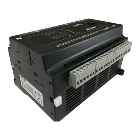
Thank you for choosing this Eaton Logic Controller (ELC). The ELCM-PH/PA series has controllers with 16 to 40 embedded I/O points and are expandable using 8 to 16 point digital I/O modules. The maximum number of I/O points, including those on the controller is 256. ELCM-PH/PA controllers can be configured with different mixes of digital, analog, and specialty I/O, to suit a wide variety of applications. -
Page 3: Electrical Specifications
61.5 Unit: mm Electrical Specifications ELCM- PH16NND PH24NND PH32NND PH40NND PA20AAD Item Power supply 100 ~ 240VAC (-15% ~ 10%), 50/60Hz 5% voltage Connector IEC standard removable terminal block (Pin pitch: 5mm) ELCM-PH/PA starts to run when the power rises to 95 ~ 100VAC and stops when the power drops to 70VAC. - Page 4 Input Point Input point type Digital input Input type DC (SINK or SOURCE) Input current 24VDC, 5mA X10 ~ X17, Input No. X0, X2 X1, X3 ~ X7 X20 ~ Action level Off → On >15VDC On → Off < 5VDC Off →...
-
Page 5: Power Budgeting
Analog Input (A/D) Analog Output (D/A) Items Voltage Current Voltage Current 250Ω Input impedance > 1MΩ 0.5Ω or lower Output impedance Tolerance carried < 500Ω > 5KΩ impedance Non-linear accuracy: ±1% of full scale within the range of ELC operation temperature Overall accuracy Maximum deviation: 1% of full scale at 20mA and +10V Response time... -
Page 6: Installation
#1: Internal Supply Current supplied: Internal BUS Max Current Consumption + Internal IO-BUS Max Current Consumption. #2: External Supply Current supplied: External I/O Max Current Consumption + External I/O Max Current Consumption for Expansion modules Current Consumption of Expansion Modules (+24VDC) Item Internal IO-BUS Max Current External I/O Max Current... -
Page 7: Power Supply
DIN Rail Mounting: When mounting the ELCM to 35mm DIN rail, be sure to use the retaining clip to stop any side-to-side movement of the ELCM and reduce the chance of wires becoming loose. The retaining clip is at the bottom of the ELCM. To secure the ELCM to DIN rail, pull down the clip, place it onto the rail and gently push the clip up. -
Page 8: I/O Point Wiring
any device may cause the breakdown of the entire control system. Therefore, we suggest you wire a protection circuit at the power supply input terminal. See the figure below. ○ ○ AC power supply:100 to 240VAC, 50/60Hz Breaker ○ Emergency stop: This button cuts off the system power supply when accidental emergency takes place. - Page 9 Relay (R) output circuit wiring ○ DC power supply ○ Emergency stop: Use an external switch ○ Fuse: Use 5 to 10A fuse at the shared terminal of output contacts to protect the output circuit ○ Transient voltage suppressor: To extend the life span of relay contacts. Diode suppression of DC load: Used with smaller loads.
- Page 10 Transistor (T) output circuit wiring ○ ○ DC power supply Emergency stop ○ Circuit protection fuse ○ The output of the transistor is “open collector”. If Y0/Y1 is set to pulse output, the output current has to be 0.05 ~ 0.5A to ensure normal operation of the output. Diode suppression: Used for smaller loads.
- Page 11 A/D and D/A External Wiring (For ELCM-PA Controller Only) A/D: Active Voltage input VI0- Shielded cable Current input VI3- Shielded cable Terminal of power module +24V Grounding (100 or less) A/D: Passive Voltage input Shielded cable Current input VI3- Shielded cable Terminal of...
- Page 12 A/D and D/A Analog Function (For ELCM-PA Controller Only) Default of analog input average times is K2. If set value = K1, ELCM takes the present value. Device Function D1062 Average times of AD (CH0 ~ CH3): 1 ~ 20, Default = K2 D1110 Average value of analog input channel 0 (AD 0) D1111...
- Page 13 +24V ELCM-PH16NNDT (8DI/8DO) ELCM-PH24NNDR/T ELCM-PH24NNDR (16DI/8DO) +24V ELCM-PH24NNDT (16DI/8DO) +24V ELCM-PH32NNDR/T +24V ELCM-PH32NNDR (16DI/16DO) +24V ELCM-PH32NNDT (16DI/16DO) ELCM-PH40NNDR/T ELCM-PH40NNDR (24DI/16DO) +24V Y16 Y17 ELCM-PH40NNDT (24DI/16DO) +24V Y16 Y17 ELCM-PA20AADR/T VI0- VI1- VI2- ELCM-PA20AADR (8DI/6DO/4AI/2AO) VI3- IO1 AG +24V VI0- VI1-...
Need help?
Do you have a question about the ELCM Series and is the answer not in the manual?
Questions and answers