Table of Contents
Advertisement
Quick Links
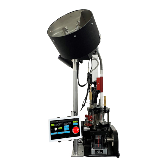
Mark 7® Evolution Autodrive
User Manual v 1.1
Read this manual completely. Understand all safety and operating instructions. Failure to
comply with the warnings and instructions may result in serious injury, illness or death.
MARK 7® RELOADING EVOLUTION USER MANUAL VERSION 1.1, COPYRIGHT 2018
1
ALL RIGHTS RESERVED
Advertisement
Table of Contents

Related Manuals for Mark 7 Evolution


Summary of Contents for Mark 7 Evolution
- Page 1 User Manual v 1.1 Read this manual completely. Understand all safety and operating instructions. Failure to comply with the warnings and instructions may result in serious injury, illness or death. MARK 7® RELOADING EVOLUTION USER MANUAL VERSION 1.1, COPYRIGHT 2018 ALL RIGHTS RESERVED...
-
Page 2: Table Of Contents
DECAPSense (Optional) .......................... 31 PRIMER ORIENTATION SENSOR ......................34 Sofware Firmware Updates ........................39 Autodrive Maintenance Intervals ......................41 Storage Recommendations ........................42 System Errors ............................43 Troubleshooting ............................43 Mark 7® Reloading EVOLUTION User Manual version 1.1, Copyright 2018 All rights reserved... -
Page 3: Important Safety Instructions
WARNING – Activities using the Mark 7® Evolution Autodrive are inherently dangerous and may lead to injury and even death. Actions as a result of using the Mark 7® product are solely the responsibility of the user – if you get injured through the reloading process or through the use of ammunition as a result of the reloading process it is your fault. - Page 4 Mark 7® Autodrive. WARNING – The Mark 7® Autodrive is designed to help automate the process of loading and processing of ammunition. Never operate the Mark 7® Autodrive at speeds higher than you have tested and are comfortable with for the type of reloading or processing that you are undertaking.
-
Page 5: Box Contents
EMI Filter kit for bulletfeeder (1X) • MicroSD Card: for software updates (1X) Top Insert: (4 items) • Tablet (1X) • Belt (1X) • Belt guard (1X) • Setup instructions (1X) MARK 7® RELOADING EVOLUTION USER MANUAL VERSION 1.1, COPYRIGHT 2018 ALL RIGHTS RESERVED... -
Page 6: Set-Up Procedures
1. Ensure that the press/Autodrive combination is on a very solid surface that does not move. The Mark 7 Autodrive is designed to sit on the 4 rubber feet in the corners, but it can also directly be bolted to your work bench by removing the 4X rubber feet in the corners, use ¼-20 bolts to fasten the baseplate to the work surface from underneath. -
Page 7: Removal Of Equipment From The Packing Carton
Major system components listed below. Gear Box Motor Motor Mount Drive Sprocket Electronics Console Belt Tensioning shoulder Bolt Rubber Feet Base Plate (4 Corners) Figure 1: Major Component Overview MARK 7® RELOADING EVOLUTION USER MANUAL VERSION 1.1, COPYRIGHT 2018 ALL RIGHTS RESERVED... -
Page 8: Mouting Evolution Press To Baseplate
Be mindful not to drag the bottom of the press against the baseplate. Mounting Hardware (QTY 4) Leave Shaft Adapter Installed Figure 2 : Mounting to Baseplate Mark 7® Reloading EVOLUTION User Manual version 1.1, Copyright 2018 All rights reserved... -
Page 9: Mounting Large Sprocket
Once the sprocket is secured insert the sprocket cap and thread in the 3/8 Set screw to lock in the link bar. Lock the set screw in place with the jam nut using a 9/16” socket. Figure 3: Mounting Large Sprocket MARK 7® RELOADING EVOLUTION USER MANUAL VERSION 1.1, COPYRIGHT 2018 ALL RIGHTS RESERVED... -
Page 10: Belt Installation
Belt must be properly tensioned for the drive to operate correctly and safely. Belt tension should be checked periodically – A properly tensioned belt should have about a ¼” of slack between the two sprockets. Mark 7® Reloading EVOLUTION User Manual version 1.1, Copyright 2018 All rights reserved... -
Page 11: Belt Guard Installation
3 screw can be installed. Do not over-tighten. Figure 5: Installing Belt Guard WARNING Never operate the machine without the belt guard installed properly. MARK 7® RELOADING EVOLUTION USER MANUAL VERSION 1.1, COPYRIGHT 2018 ALL RIGHTS RESERVED... -
Page 12: Tablet Holder Install
Be mindful that the arms do not cover the power or the micro-USB inputs on the tablet. Figure 6: Tablet Installed in holder Mark 7® Reloading EVOLUTION User Manual version 1.1, Copyright 2018 All rights reserved... -
Page 13: Tablet Cable Outlet Installation
Do not zip tie the tablet cables to case feeder pole, case feeder power cord or Mr. Bulletfeeder power cords. MARK 7® RELOADING EVOLUTION USER MANUAL VERSION 1.1, COPYRIGHT 2018 ALL RIGHTS RESERVED... -
Page 14: Console Rear I/O Inputs
USB: Motor to Console USB data communication cable 8-Pin: Motor to console signal cable Port #7. Digital Powder Measure (optional) Port #6. Remote Stop (optional) Port #5. DecapSense (optional) Mark 7® Reloading EVOLUTION User Manual version 1.1, Copyright 2018 All rights reserved... -
Page 15: Console Side I/O Inputs
Never power on the console switch without the 6-pin molex connector plugged in and never install this connector with the power already on since the DC voltage would damage the motor's input contacts. MARK 7® RELOADING EVOLUTION USER MANUAL VERSION 1.1, COPYRIGHT 2018 ALL RIGHTS RESERVED... -
Page 16: Emi Filter For Bulletfeeders
10. EMI Filter for Mr.BulletFeeder There is an external capacitor cable assembly included with your Mark 7® Autodrive. Ensure that this is attached to the bullet dropper assembly between that assembly and the cables to the bullet feeder to ensure error-free operation. -
Page 17: Manully Driving The Press
No cables are near the moving parts of the press, secure any loose cables away from the moving components Hex / shaft adapter attachment pint Figure 11: Manually driving the Evolution MARK 7® RELOADING EVOLUTION USER MANUAL VERSION 1.1, COPYRIGHT 2018 ALL RIGHTS RESERVED... -
Page 18: Operating Instructions
Make sure quick boot mode is DISABLED (uncheck the “Quickboot mode” pop-up when it appears when you shut the tablet off). Mark 7® Reloading EVOLUTION User Manual version 1.1, Copyright 2018 All rights reserved... - Page 19 The image above is the first screen displayed after launching the Reloader application. The operator must accept the terms and conditions on the waiver screen also available on the Mark 7® Reloading website. If the operator accepts these terms the operator can touch ACCEPT on the screen. If the operator does not accept these terms they must touch DENY which will immediately close the application.
- Page 20 Figure 14: System Control Screen CALIBRATE - CALIBRATE signals the Mark 7® Autodrive to find the top and bottom of the presses stroke. Once calibration is completed all Mark 7® Autodrive features can be used. The shellplate must be clear when calibrating.
-
Page 21: Digital Clutch Setting
JOG UP - The JOG UP function will incrementally move the press upwards. The JOG functions are useful in clearing jams that may occur. The JOG UP function will only work when the Mark 7® Autodrive is at a stop. - Page 22 Stroke, dropping the torque primarily on the upstroke to a minimum baseline level. This increases the machines sensitivity if a jam occurs in the upstroke due to a case feed or shell plate indexing issue. Mark 7® Reloading EVOLUTION User Manual version 1.1, Copyright 2018 All rights reserved...
- Page 23 SET PRIMER - The operator has the ability to set the number of primers used before the Mark 7® Autodrive ends its current run. SET BRASS - The operator has the ability to set the number of brass used before the Mark 7® Autodrive ends its current run.
-
Page 24: Sensors
We recommend disabling any of the sensors you don’t have installed on your system. RUN, END CYCLE, and STOP functions have the same functionality on the Setup Screen as they do on the Control Screen and the Monitors Screen Mark 7® Reloading EVOLUTION User Manual version 1.1, Copyright 2018 All rights reserved... - Page 25 RUN, END CYCLE, and STOP functions have the same functionality on the Setup Screen as they do on the Control Screen and the Monitors Screen - Clearing Jams MARK 7® RELOADING EVOLUTION USER MANUAL VERSION 1.1, COPYRIGHT 2018 ALL RIGHTS RESERVED...
- Page 26 In some cases, a hard jam may occur. If the jog buttons do not move the tool head then the Mark 7® Autodrive needs to be powered down. Once powered down you may attempt to manually clear the jam.
- Page 27 When the sensor is plugged into the Autodrive the machine can stop and send a notification to the tablet when the sensor is activated. Figure 20: Removing Battery from PrimerSense Figure 21: PrimerSense® Sensor Notification MARK 7® RELOADING EVOLUTION USER MANUAL VERSION 1.1, COPYRIGHT 2018 ALL RIGHTS RESERVED...
- Page 28 Figure 22: Mark 7® SwageSense® Installation Instructions 1. Remove the Fixed swage rod installed on the Evolution and Replace with the Swagesense Assembly. Refer to the exploded view for details. 2. SwageSense® plugs into the cable assembly pigtail off of the PrimerSense® into port #1 on the console Mark 7®...
- Page 29 To adjust tighten the setscrew until you hear the switch trigger, then back it off a ¼ turn and lock down with the jam nut. MARK 7® RELOADING EVOLUTION USER MANUAL VERSION 1.1, COPYRIGHT 2018 ALL RIGHTS RESERVED...
- Page 30 Figure 24: Micro switch Adjustment 3. When the SwageSense® switch is triggered the following notification will appear on the reloader application. Figure 25: SwageSense® Notification Mark 7® Reloading EVOLUTION User Manual version 1.1, Copyright 2018 All rights reserved...
-
Page 31: Decapsense (Optional)
Figure 26: Evolution DecapSense®™ DecapSense® Sensor™ Operating Instructions 1. The Mark 7® DecapSense ® must be connected to the console before you enter the Reloading application and enabled on the sensor tab. 2. Calibrate and run the machine as normal. When a spent primer is not ejected the following notification box will appear. - Page 32 Figure 28: Sensor Obstructed Cleaning required Message WARNING – cleaning intervals of the Mark 7® DecapSense® will vary dramatically based upon many factors. WE SUGGEST CLEANING THE MARK 7® DecapSense™ AS OFTEN AS PRACTICAL – IT IS UP-TO YOU TO ENSURE THE SENSOR IS CLEAN.
- Page 33 Primer Orientation Sensor Instructions The Primer Orientation Sensor is compatible on all Revolution and Evolution Press platforms, including systems equipped with No priming, Standard priming and Automated priming Systems. The sensor is packaged in a single corrugated box (6” X 6” X 1-1/4"). Please check the packaging contents below before installing the sensor.
-
Page 34: Primer Orientation Sensor
Shellplate must be removed or lifted up to remove the spacer housing. Although it’s not required, we do recommend to remove the tool head for full access. Below are the installation steps for installing the sensor on a Revolution (shown) or Evolution Press (same procedure). Step 1: Removing Press Top End 1. - Page 35 Figure 32: Probe Retractor Installed with Springs NOTE: The probe must be installed at a slight angle in order to clear the undercut in the priming housing. MARK 7® RELOADING EVOLUTION USER MANUAL VERSION 1.1, COPYRIGHT 2018 ALL RIGHTS RESERVED...
- Page 36 4. Install Tool Head* Note: When installing the Tool Head always perform the final tightening of the Tool Head with the crank assembly in the down position. Mark 7® Reloading EVOLUTION User Manual version 1.1, Copyright 2018 All rights reserved...
- Page 37 Figure 34 : Setting Optical Sensor Position Step 6: Plug the Sensor into Port #2 on the rear of the electronics unit Figure 35 : Plug Sensor into Port #2 as Shown MARK 7® RELOADING EVOLUTION USER MANUAL VERSION 1.1, COPYRIGHT 2018 ALL RIGHTS RESERVED...
- Page 38 Shellplate on the upstroke a notification can appear. If the notification appears on the screen clear the Shellplate and check the mechanical indexing components before continuing operating the press. Mark 7® Reloading EVOLUTION User Manual version 1.1, Copyright 2018 All rights reserved...
-
Page 39: Sofware Firmware Updates
*May only be included in some update packages 3. Insert the Micro SD card into the SD card adapter that was provided with the Mark 7® Autodrive and load the downloaded .hex and .apk file(s) onto the SD card via a SD card reader. - Page 40 UPLOAD and press CLOSE when complete. Select the Reloader application and confirm that software version and firmware at the waiver screen is the same as what was just installed. Figure 39: Firmware installation Process Mark 7® Reloading EVOLUTION User Manual version 1.1, Copyright 2018 All rights reserved...
-
Page 41: Autodrive Maintenance Intervals
4. While looking into the hole rotate the small sprocket very slowly. You will see the shaft collar spinning inside the hole 5. There are 2X Metric socket head cap screws clamping the gearbox shaft collar to the motor output shaft. MARK 7® RELOADING EVOLUTION USER MANUAL VERSION 1.1, COPYRIGHT 2018 ALL RIGHTS RESERVED... -
Page 42: Storage Recommendations
3. Turn off the power to the console of the autodrive 4. Turn off the power to the case feeder and the bullet feeder 5. Turn off the power to the tablet Mark 7® Reloading EVOLUTION User Manual version 1.1, Copyright 2018 All rights reserved... -
Page 43: System Errors
• Make sure the USB connectors are secure and away from the moving components. Troubleshooting Refer to the Mark 7 Digital Community at www.markvii-loading.com/community for articles and videos to assist with troubleshooting. Please contact us for technical support Phone: 1-888-462-7577 (option #3 Technical Support) Hours: 8:30am-5:00pm, ET, M–F...
Need help?
Do you have a question about the Evolution and is the answer not in the manual?
Questions and answers