Table of Contents
Advertisement
Quick Links
www.ti.com
User's Guide
INA228, INA229, INA237, INA238, and INA239 EVM User's
Guide
This user's guide describes the characteristics, operation, and use of the INA228, INA229, INA237, INA238,
and INA239 evaluation modules (EVMs). These EVMs are designed to evaluate the performance of the
INA228, INA229, INA237, INA238, and INA239. Throughout this document, the terms evaluation board,
evaluation module, and EVM are synonymous with the INA228EVM, INA229EVM, INA237EVM, INA238EVM,
and INA239EVM. This document includes a schematic, reference printed-circuit board (PCB) layouts, and a
complete bill of materials (BOM).
SBOU241C – APRIL 2020 – REVISED JULY 2021
Submit Document Feedback
ABSTRACT
INA228, INA229, INA237, INA238, and INA239 EVM User's Guide
Copyright © 2021 Texas Instruments Incorporated
1
Advertisement
Table of Contents

Related Manuals for Texas Instruments INA228


Summary of Contents for Texas Instruments INA228
- Page 1 Guide ABSTRACT This user’s guide describes the characteristics, operation, and use of the INA228, INA229, INA237, INA238, and INA239 evaluation modules (EVMs). These EVMs are designed to evaluate the performance of the INA228, INA229, INA237, INA238, and INA239. Throughout this document, the terms evaluation board, evaluation module, and EVM are synonymous with the INA228EVM, INA229EVM, INA237EVM, INA238EVM, and INA239EVM.
-
Page 2: Table Of Contents
Table of Contents www.ti.com Table of Contents Trademarks....................................2 General Texas Instruments High Voltage Evaluation (TI HV EMV) User Safety Guidelines..........Overview....................................5 2.1 Kit Contents..................................5 2.2 Related Documentation From Texas Instruments......................3 Hardware....................................3.1 Features..................................... Operation....................................7 4.1 Quick Start Setup................................4.2 EVM Operation...................................7... -
Page 3: General Texas Instruments High Voltage Evaluation (Ti Hv Emv) User Safety Guidelines
General Texas Instruments High Voltage Evaluation (TI HV EMV) User Safety Guidelines General Texas Instruments High Voltage Evaluation (TI HV EMV) User Safety Guidelines WARNING Always follow TI's set-up and application instructions, including use of all interface components within their recommended electrical rated voltage and power limits. - Page 4 General Texas Instruments High Voltage Evaluation (TI HV EMV) User Safety Guidelines www.ti.com WARNING While the EVM is energized, never touch the EVM or its electrical circuits, as they could be at high voltages capable of causing electrical shock hazard.
-
Page 5: Overview
The devices can measure a selectable full-scale differential input of ±163.84 mV or ±40.96 mV across the shunt with common-mode voltage support from –0.3 V to +85 V. For the INA228 and INA229, built-in digital accumulation calculates average power, internal die temperature, energy, and charge accumulation. -
Page 6: Related Documentation From Texas Instruments
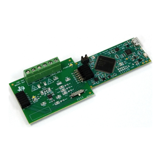
(EMC) testing. The EVM consists of two printed-circuit boards (PCBs). The larger PCB is referred to as the EVM, and has either the INA228, INA229, INA237, INA238, or INA239 installed. The smaller PCB is referred to as the SCB Controller, and is used to interface the EVM with the GUI. -
Page 7: Operation
The GUI only supports one EVM/device type at a time, up to 4 EVMs total. Figure 4-2. Multiple EVMs Connected to SCB Controller SBOU241C – APRIL 2020 – REVISED JULY 2021 INA228, INA229, INA237, INA238, and INA239 EVM User’s Guide Submit Document Feedback Copyright © 2021 Texas Instruments Incorporated... - Page 8 If the PAMB board is being used instead, these test points are located near PK1 and PK2. With the MCU in DFU mode, the firmware can now be uploaded through the method outlined in Step INA228, INA229, INA237, INA238, and INA239 EVM User’s Guide SBOU241C – APRIL 2020 – REVISED JULY 2021 Submit Document Feedback...
- Page 9 4-5. These prompts will appear after you close the README.md dialog. Figure 4-5. TI Cloud Agent SBOU241C – APRIL 2020 – REVISED JULY 2021 INA228, INA229, INA237, INA238, and INA239 EVM User’s Guide Submit Document Feedback Copyright © 2021 Texas Instruments Incorporated...
- Page 10 Avoid using long cables and USB hubs. • If using a desktop PC, try a USB port on the back. INA228, INA229, INA237, INA238, and INA239 EVM User’s Guide SBOU241C – APRIL 2020 – REVISED JULY 2021 Submit Document Feedback...
- Page 11 Figure 4-10, which may change based on the device connected. Figure 4-10. Configuration Tool SBOU241C – APRIL 2020 – REVISED JULY 2021 INA228, INA229, INA237, INA238, and INA239 EVM User’s Guide Submit Document Feedback Copyright © 2021 Texas Instruments Incorporated...
- Page 12 – If a Max Expected Current is not specified, then the True Max Current field will be used instead. INA228, INA229, INA237, INA238, and INA239 EVM User’s Guide SBOU241C – APRIL 2020 – REVISED JULY 2021 Submit Document Feedback...
- Page 13 To do this, go to File -> Register Data, as shown in Figure 4-12. SBOU241C – APRIL 2020 – REVISED JULY 2021 INA228, INA229, INA237, INA238, and INA239 EVM User’s Guide Submit Document Feedback Copyright © 2021 Texas Instruments Incorporated...
- Page 14 – If you disable one of these settings while the EVM is collecting data, then the plot will not show, but data will still be collected and the plot will update in the background. Simply reselect to show data. INA228, INA229, INA237, INA238, and INA239 EVM User’s Guide SBOU241C – APRIL 2020 – REVISED JULY 2021 Submit Document Feedback Copyright ©...
- Page 15 – For the DIETEMP Result, the units can also be toggled between °C and °F. SBOU241C – APRIL 2020 – REVISED JULY 2021 INA228, INA229, INA237, INA238, and INA239 EVM User’s Guide Submit Document Feedback Copyright © 2021 Texas Instruments Incorporated...
- Page 16 (including the terminal block J1), as shown in Figure 4-14. Figure 4-14. IN+ and IN– Wiring for More Than 10A INA228, INA229, INA237, INA238, and INA239 EVM User’s Guide SBOU241C – APRIL 2020 – REVISED JULY 2021 Submit Document Feedback Copyright © 2021 Texas Instruments Incorporated...
- Page 17 5. Power on the system, and observe the device states and outputs through the GUI. SBOU241C – APRIL 2020 – REVISED JULY 2021 INA228, INA229, INA237, INA238, and INA239 EVM User’s Guide Submit Document Feedback Copyright © 2021 Texas Instruments Incorporated...
- Page 18 – For this example, the EVM would return the results and state ("idle" or "collecting") in JSON format: {"acknowledge":"wreg 0x01 0xfb69"} {"console":"Writing 0xfb69 to ADC_CONFIG register"} {"evm_state":"idle"} INA228, INA229, INA237, INA238, and INA239 EVM User’s Guide SBOU241C – APRIL 2020 – REVISED JULY 2021 Submit Document Feedback Copyright © 2021 Texas Instruments Incorporated...
- Page 19 • The register data value, given in bytes with the most significant byte first. SBOU241C – APRIL 2020 – REVISED JULY 2021 INA228, INA229, INA237, INA238, and INA239 EVM User’s Guide Submit Document Feedback Copyright © 2021 Texas Instruments Incorporated...
- Page 20 When using SENS064A on the PAMB with the new GUI/Firmware, only 1 device can be used at a time, with SW1 on the EVM set to CS3, and the GUI switch setting set to CS1. INA228, INA229, INA237, INA238, and INA239 EVM User’s Guide SBOU241C – APRIL 2020 – REVISED JULY 2021 Submit Document Feedback Copyright ©...
-
Page 21: Circuitry
This section describes the main INA device and supporting components. U1 is the main INA current-sensing device (either the INA228, INA229, INA237, INA238, or INA239). C1 and C2 are bypass capacitors that are placed near the sensor to help mitigate power supply noise and provide current quickly to the device when needed. -
Page 22: Schematics, Pcb Layout, And Bill Of Materials
MNT_2 MNT_3 MNT_4 CUS-14TB +3V3 MNT_1 MNT_2 MNT_3 MNT_4 CUS-14TB Figure 6-1. SENS063 Schematic INA228, INA229, INA237, INA238, and INA239 EVM User’s Guide SBOU241C – APRIL 2020 – REVISED JULY 2021 Submit Document Feedback Copyright © 2021 Texas Instruments Incorporated... - Page 23 Trim the leads under J1 (back of PCB) to give clearance from surface Figure 6-2. SENS063 Hardware Schematic SBOU241C – APRIL 2020 – REVISED JULY 2021 INA228, INA229, INA237, INA238, and INA239 EVM User’s Guide Submit Document Feedback Copyright © 2021 Texas Instruments Incorporated...
- Page 24 INA239AIDGSR ALERT 4.7k MNT_1 MNT_2 MNT_3 MNT_4 CUS-14TB +3V3 +3V3 Figure 6-3. SENS064 Schematic INA228, INA229, INA237, INA238, and INA239 EVM User’s Guide SBOU241C – APRIL 2020 – REVISED JULY 2021 Submit Document Feedback Copyright © 2021 Texas Instruments Incorporated...
- Page 25 Trim the leads under J1 (back of PCB) to give clearance from surface Figure 6-4. SENS064 Hardware Schematic SBOU241C – APRIL 2020 – REVISED JULY 2021 INA228, INA229, INA237, INA238, and INA239 EVM User’s Guide Submit Document Feedback Copyright © 2021 Texas Instruments Incorporated...
-
Page 26: Pcb Layout
Figure 6-6. SENS063 Top Layer Figure 6-8. SENS063 Bottom Layer Figure 6-7. SENS063 Bottom View INA228, INA229, INA237, INA238, and INA239 EVM User’s Guide SBOU241C – APRIL 2020 – REVISED JULY 2021 Submit Document Feedback Copyright © 2021 Texas Instruments Incorporated... - Page 27 Figure 6-10. SENS064 Top Layer Figure 6-12. SENS064 Bottom Layer Figure 6-11. SENS064 Bottom View SBOU241C – APRIL 2020 – REVISED JULY 2021 INA228, INA229, INA237, INA238, and INA239 EVM User’s Guide Submit Document Feedback Copyright © 2021 Texas Instruments Incorporated...
-
Page 28: Bill Of Materials
SW0, SW1 Slide Switch SP4T Surface Mount, Right Angle SMT_SW_11MM3_4MM1 CUS-14TB Nidec Copal Electronics INA228, INA229, INA237, INA238, and INA239 EVM User’s Guide SBOU241C – APRIL 2020 – REVISED JULY 2021 Submit Document Feedback Copyright © 2021 Texas Instruments Incorporated... - Page 29 Thermal Transfer Printable Labels, 0.650" W x 0.200" H - 10,000 per roll PCB Label 0.650 x 0.200 THT-14-423-10 Brady inch SBOU241C – APRIL 2020 – REVISED JULY 2021 INA228, INA229, INA237, INA238, and INA239 EVM User’s Guide Submit Document Feedback Copyright © 2021 Texas Instruments Incorporated...
- Page 30 10 mOhms ±0.5% 2W Chip Resistor 2512 (6432 Metric) Automotive AEC-Q200, Current 2512 PCS2512DR0100ET Ohmite Sense, Moisture Resistant Metal Film INA228, INA229, INA237, INA238, and INA239 EVM User’s Guide SBOU241C – APRIL 2020 – REVISED JULY 2021 Submit Document Feedback Copyright © 2021 Texas Instruments Incorporated...
-
Page 31: Revision History
Direct EVM Serial Communication section to explain how to communicate with the EVM via direct serial communication............................SBOU241C – APRIL 2020 – REVISED JULY 2021 INA228, INA229, INA237, INA238, and INA239 EVM User’s Guide Submit Document Feedback Copyright © 2021 Texas Instruments Incorporated... - Page 32 TI products. TI’s provision of these resources does not expand or otherwise alter TI’s applicable warranties or warranty disclaimers for TI products.IMPORTANT NOTICE Mailing Address: Texas Instruments, Post Office Box 655303, Dallas, Texas 75265 Copyright © 2021, Texas Instruments Incorporated...
Need help?
Do you have a question about the INA228 and is the answer not in the manual?
Questions and answers