Advertisement
Quick Links
Fan coil actuator 2-gang
Fan coil actuator 2-gang
Art.-No.: FCA 2 REGHE
Operating instructions
1 Safety instructions
Electrical equipment may only be installed and fitted by electrically skilled persons.
Failure to observe the instructions may cause damage to the device and result in fire and
other hazards.
Danger of electric shock. Always disconnect before carrying out work on the devise or
load. At the same time, take into account all circuit breakers that supply dangerous
voltage to the device or load.
Danger of electric shock. Device is not suitable for disconnection from supply voltage.
Danger of electric shock on the SELV/PELV installation. Not suitable for switching SELV/
PELV voltages.
Do not connect any three-phase motors. Device can be damaged.
These instructions are an integral part of the product, and must remain with the end
customer.
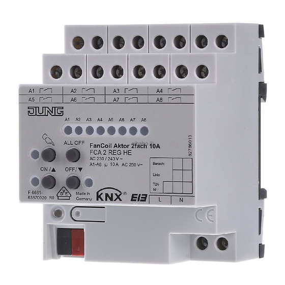
2 Device components
(1) Button field for manual control
(2) Programming button and LEDs
(3) KNX connection
(4) Connection for mains supply
(5) Status LEDs for outputs
(6) Connection of fan coil unit
82565513
J:0082565513
Figure 1: Device components front view
1/11
20.12.2011
Advertisement

Subscribe to Our Youtube Channel
Related Manuals for Jung FCA 2 REGHE


Summary of Contents for Jung FCA 2 REGHE
- Page 1 Fan coil actuator 2-gang Fan coil actuator 2-gang Art.-No.: FCA 2 REGHE Operating instructions 1 Safety instructions Electrical equipment may only be installed and fitted by electrically skilled persons. Failure to observe the instructions may cause damage to the device and result in fire and other hazards.
-
Page 2: Operation
Fan coil actuator 2-gang 3 Function System information This device is a product of the KNX system and complies with the KNX directives. Detailed technical knowledge obtained in KNX training courses is a prerequisite to proper understanding. The function of this device depends upon the software. Detailed information on loadable software and attainable functionality as well as the software itself can be obtained from the manufacturer´s product database. - Page 3 Fan coil actuator 2-gang (10) LED ON/n – Switched on, Manual operation (11) Button OFF/o – Switch off (12) LED OFF/o – Switched off, Manual operation (13) Button ALL OFF – All outputs off Status indication The status LEDs A1...A8 (5) indicate the states of the outputs. Off: Output switched off On: Output switched on Flashes slowly: Output in manual mode...
- Page 4 Fan coil actuator 2-gang Fan outputs: When switching off the manual control, the outputs, depending on the programming, switch to the active position, e.g. forced position. Switching outputs: When the manual operation is switched off, the output relays remain in the current position.
- Page 5 Fan coil actuator 2-gang 5 Information for electrically skilled persons 5.1 Fitting and electrical connection DANGER! Electrical shock when live parts are touched. Electrical shocks can be fatal. Before carrying out work on the device or load, disengage all the corresponding circuit breakers.
- Page 6 Fan coil actuator 2-gang Figure 3: Connection example – load connection for 1 fan-coil output Operating mode A3...A8 Heating valve Fan levels Cooling valve Fan levels Heating/cooling valve Fan levels Cooling valve Heating valve Fan levels Cooling valve Heating valve Fan levels Table 2: Output assignment 1 fan-coil output Figure 4: Single-channel fan levels for hierarchical switching –...
- Page 7 Fan coil actuator 2-gang Figure 5: Single-channel fan levels for individual switching – powered outputs Figure 6: Connection example – load connection for 2 fan-coil outputs Operating mode A1 / A5 A2-4 / A6-8 Heating valve Fan levels Cooling valve Fan levels Heating/cooling valve Fan levels...
- Page 8 Fan coil actuator 2-gang Figure 7: Two-channel fan levels for hierarchical switching – powered outputs Figure 8: Two-channel fan levels for individual switching – powered outputs Installing the cover It is necessary to install a cover to protect the bus connection against hazardous voltages in the connection area.
- Page 9 Fan coil actuator 2-gang Removing the cover Figure 10: Removing the cover Press the cover to the side and pull it off (figure 10). 5.2 Commissioning Load the address and the application software Switch on the bus voltage Assign physical address. Load the application software into the device.
-
Page 10: Troubleshooting
Fan coil actuator 2-gang uncompensated 1000 W parallel compensated 1160 W (140 µF) Duo circuit 2300 W (140 µF) Compact fluorescent lamps uncompensated 1000 W parallel compensated 1160 W (140 µF) Mercury vapour lamps uncompensated 1000 W parallel compensated 1160 W (140 µF) Connections supply and load Connection mode Screw terminal... -
Page 11: Warranty
We provide a warranty as provided for by law. Please send the unit postage-free with a description of the defect to our central customer service office: ALBRECHT JUNG GMBH & CO. KG Service Center Kupferstr. 17-19 D-44532 Lünen Service-Line: +49 (0) 23 55 .
Need help?
Do you have a question about the FCA 2 REGHE and is the answer not in the manual?
Questions and answers