Advertisement
Quick Links
Cell Phone Signal Booster
Manufactured and Warranted by
www.solidRFinc.com
customer service number:
Office
(435) 319-6858
Toll Free
(877) 579-7878
Signal Plus
Manual
SolidRF Inc.
Operational Diagram
(How It Works)
Package Contents
Page 2
Basic Signal Level Knowledge
Page 3
Preparation
Page 4 - 7
Installation Step By Step
Page 8 - 16
Trouble Shooting
Page 17 - 18
Technical Specification
Warranty Information
Page 19
Safety Guidelines
Page 20
1
Advertisement

Subscribe to Our Youtube Channel
Related Manuals for SolidRF Signal Plus


Summary of Contents for SolidRF Signal Plus
- Page 1 Signal Plus Operational Diagram (How It Works) Cell Phone Signal Booster Package Contents Manual Page 2 Basic Signal Level Knowledge Page 3 Preparation Page 4 - 7 Installation Step By Step Page 8 - 16 Trouble Shooting Page 17 - 18...
- Page 2 Working Diagram (How It Works) The outdoor antenna catches the signal from the tower. Sends outside signal to the booster through a coax cable. The booster amplifies the signal then rebroadcasts the signal indoors to all mobile devices within range. The system also works in reverse;...
- Page 3 Signal transmission loss and power level Coverage area ability Note: FCC regulations limit the amplification of all cell phone boosters in order to prevent damage to the telecommunications infrastructure. Therefore, the maximum coverage area of a booster depends on the original power level of the signal captured by the outdoor unit.
- Page 4 Preparation Find your cell tower nearby! There are a variety of resources available online, here is a third party website recommended. Use it to locate your nearest cell tower: www.cellmapper.net Note: This is very important step. If we use the wrong direction, we won't have good result.
- Page 5 Step 3:. Select Provider. You will find the cell tower around your house. Select Provider...
- Page 6 Step 4: Find your cell tower Click the red or green dot on the map that represents the base station, and the detailed information of the base station will be displayed. • The first important information, you can see from the above four pictures, the coverage area (shaded part) of each base station is different.
- Page 7 Find The dBm Reading On Your Phone Having an accurate measurement of signal strength in decibels (dBm) is crucial when installing your system. Decibels accurately measure the signal strength you are receiving. Note: Turn off your cell phone’s WiFi to ensure you are checking the cellular connection. The dBm reading will be refreshed every 30-60 seconds.
- Page 8 Test Installation We STRONGLY recommend doing a test installation before finalizing the installation. Doing a test installation of your cell phone booster ensures that you will get the optimal performance from your system. Step1: Select the Location for the Outside Unit Note:This is the most critical step and will determine the overall performance of the booster system.
- Page 9 Step 2: Temporarily Mount the Outside Antenna In addition to the four corners of the building, the chimney and the pole above the roof can also be selected. As long as the installation distance between indoor and outdoor antennas is maintained enough, satisfactory results can also be achieved. Use one of the three options to mount the outside antenna on your roof on the side of the house with the strongest signal.
- Page 10 Step3: Select the Location for the Inside Antenna In order to achieve the best signal coverage effect, there is a certain distance requirement between the indoor and outdoor units. Make sure the inside and outside units are facing away from each other. Minimum Required Separation Distance Between Indoor and Outdoor Antenna:...
- Page 11 Antenna mutual position( top view) Avoid cross antenna beams( the best Ensure the distance, allow the antenna to solution) cross the rear beam( good solution) Do not face the outdoor antenna to the Do not face the indoor antenna to the indoor antenna outdoor antenna The indoor antenna is a panel...
- Page 12 2.Connect the outside antenna to the 3.Connect the 15 ft RG6 cable to the “OUTSIDE” port of booster. booster at the “INSIDE” port. 4.Connect the other end of the coax cable to splitter at the “INPUT” port, and two inside antennas' cables connect to the other side port.
- Page 13 Step5: Evaluate the Effects • Now that the booster is up-and-running, re-test the signal strength inside your home at the same locations from Step 1. If the number is higher (dBm reading is closer to zero) than the original reading, your booster is working. •...
- Page 14 Step6: Finalizing Outdoor Antenna Installation Once you have tested the performance of the signal booster and made all necessary adjustments, it’s time to finalize the installation. Outdoor Antenna Installation Make sure that the outside unit is mounted at least 3 feet away from any windows. Option A : Outside Roof Pole Mount Option B : Mounting on the side of (Best Choice) Use an existing pole to...
- Page 15 Step7: Finalizing Indoor Installation a. Choose right position for the indoor antenna • 20 cm away from facing any other metallic objects • 50 cm away from any windows • The inside antenna should be facing the location of the signal dead zone/weak signal area inside the building b.
- Page 16 Caution Seal and Fix the Connector Secure the cable near the antenna to prevent cable damage caused by wind shaking Properly Handle Excess Cables If the coiled cable is too close to the antenna or booster, the system will be unstable. Make sure these coiled cables are more than 6 feet(2 meters) from the antenna or booster Make sure these excess coiled cables are more than 6 feet(2 meters) from the antenna...
-
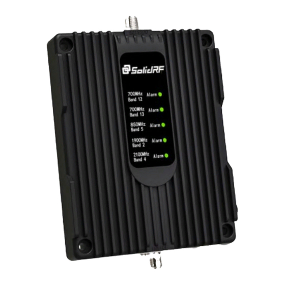
Page 17: Power Light
Quick Trouble shooting Correct functioning: • Power Light should be solid white( the logo on the panel) • The indicator light on the front panel indicates the status of the booster. Every time the booster is turned on, all the indicators will turn green for a period of time and then go out. - Page 18 Trouble Shooting: No Signal Improvement Step 5. Trees will greatly attenuate wireless signals. If there are tall trees within 100 feet of the house. At the same time you can't find a stable signal above 3 bars, the outdoor antenna needs to be erected 60%(at least) to 80%(best) of the tree height. Never exceed the trees! Step 6.
- Page 19 SolidRF. This warranty does not apply to any signal booster components determined by SolidRF to have been subjected to misuse, abuse, neglect, tampering, or mishandling that result in damages to the physical or electronic properties of the product.
- Page 20 Use only the power supply provided in this package. Use of a non-SolidRF product or accessory may result in damage to the equipment or components of the equipment. The inside unit is designed for use in an indoor, temperature-controlled environment (less than 100 degrees Fahrenheit).
Need help?
Do you have a question about the Signal Plus and is the answer not in the manual?
Questions and answers