Advertisement
Quick Links
SR14652002A
Cell Phone Signal Booster
Manufactured and Warranted by
www.solidRFinc.com
customer service number:
Office
(435) 319‐6858
Toll Free
(877) 579‐7878
US:
Support@SolidRFINC.com
Canada:
Support@SolidRF.ca
Manual
SolidRF Inc.
Operational Diagram
(How It Works)
Package Contents
Page 2
Basic Signal Level Knowledge
Page 3
Preparation
Page 4 ‐ 7
Installation Step By Step
Page 8 ‐ 16
Trouble Shooting
Page 17 ‐ 26
Technical Specification
Warranty Information
Page 27
Safety Guidelines
Page 28
1
Advertisement

Subscribe to Our Youtube Channel
Related Manuals for SolidRF SR14652002A


Summary of Contents for SolidRF SR14652002A
- Page 1 SR14652002A Operational Diagram Cell Phone Signal Booster (How It Works) Manual Package Contents Page 2 Basic Signal Level Knowledge Page 3 Preparation Page 4 ‐ 7 Installation Step By Step Page 8 ‐ 16 Trouble Shooting Page 17 ‐ 26 Technical Specification Warranty Information Page 27 Manufactured and Warranted by SolidRF Inc. Safety Guidelines www.solidRFinc.com Page 28 customer service number: Office (435) 319‐6858 Toll Free (877) 579‐7878 Support@SolidRFINC.com Canada: Support@SolidRF.ca...
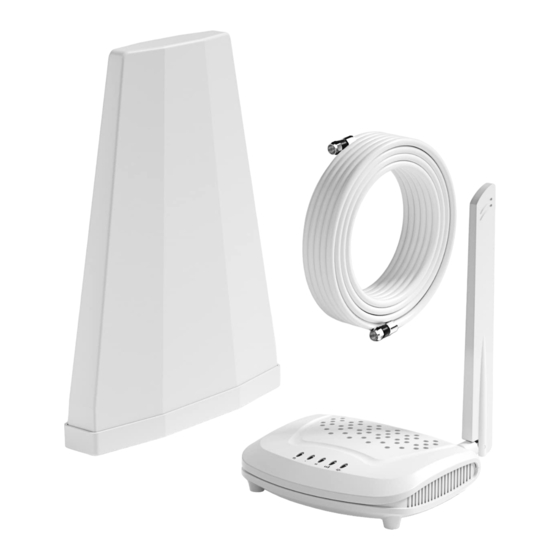
- Page 2 Working Diagram (How It Works) The outdoor antenna catches the signal from the tower. Sends outside signal to the booster through a coax cable. The booster amplifies the signal then rebroadcasts the signal indoors to all mobile devices within range. The system also works in reverse; amplifying outgoing signal back to the tower. The coverage area and the strength of the boosted signal are directly related to two key factors: 1. Signal strength received by the outdoor unit. So, setting up the outside unit where the signal is the strongest will provide the best results. 2. Distance of separation between the outdoor unit and the indoor unit. Package Contents The kit includes the following items: 1. Outdoor Antenna (with mounting kits); 2. Booster(with indoor antenna); 3. Power supply; 4. 60 ft of RG6 cable, for connecting the outdoor unit and indoor unit; Outdoor Antenna Power supply RG6 cable Booster & Indoor Antenna...
- Page 3 Signal transmission loss and power level Coverage area ability Note: FCC regulations limit the amplification of all cell phone boosters in order to prevent damage to the telecommunications infrastructure. Therefore, the maximum coverage area of a booster depends on the original power level of the signal captured by the outdoor unit. Notice: Not recommended when outdoor signal strength is less than ‐110dbm(3G/1x) or ‐120dBm(4G/LTE). The resulting coverage area of the boosted signal will be prohibitively small. Power level Coverage Area at the outdoor antenna location (sq. ft.) Strong (5 bars on the cellphone) 2,000 Medium (3~4 bars on the cellphone) 1,000 Weak (1~2 bars on the cellphone)
- Page 4 Preparation Find your cell tower nearby! There are a variety of resources available online, here is a third party website recommended. Use it to locate your nearest cell tower: www.cellmapper.net Note: This is very important step. If we use the wrong direction, we won't have good result. Step 1: Visit website www.cellmapper.net www.cellmapper.net Step 2: Find your location on the map and zoom in on your area...
- Page 5 Step 3:. Select Provider. You will find the cell tower around your house. Select Provider ...
- Page 6 Step 4: Find your cell tower Click the red or green dot on the map that represents the base station, and the detailed information of the base station will be displayed. • The first important information, you can see from the above four pictures, the coverage area (shaded part) of each base station is different. You have to find a base station with signal coverage to your house, or the coverage direction is facing you, and the coverage area is closest to you. • The second important information, you can scroll the information content on the left to find the specific carrier information of this base station, including the communication standard and frequency band. Please reference the left picture, “LTE” and “B2 FDD”(Band 2, FDD).
- Page 7 Find The dBm Reading and Band Number On Your Phone Having an accurate measurement of signal strength in decibels (dBm) is crucial when installing your system. Decibels accurately measure the signal strength you are receiving. Note: Turn off your cell phone’s WiFi to ensure you are checking the cellular connection. The dBm reading will be refreshed every 30‐60 seconds. Want faster results? Once you have a reading, turn on airplane mode. Wait 15 seconds. Turn off airplane mode. The signal strength reading is refreshed. iPhone: dial *3001#12345#* then press call Band number Receive level dBm Android: download third part APP‐LTE Discovery Band number Receive level dBm...
- Page 8 Test Installation We STRONGLY recommend doing a test installation before finalizing the installation. Doing a test installation of your cell phone booster ensures that you will get the optimal performance from your system. Step1: Select the Location for the Outside Unit Note:This is the most critical step and will determine the overall performance of the booster system. Generally, the strongest signal will be located on the side of your home facing the nearest cell tower. Keep in mind, the signal strength at ground level may be different from the signal strength at or above the roofline due to obstructions (trees, other buildings, etc.) that block the incoming signal. In most situations, the strongest signal is found about 25 feet above the ground on the side of your home facing the nearest cell tower. The most ideal installation position is the corner of the building, choose the one facing your cell tower. Four corner of the building are the most ideal position Choose the one facing your cell tower...
- Page 9 Step 2: Temporarily Mount the Outside Antenna In addition to the four corners of the building, the chimney and the pole above the roof can also be selected. As long as the installation distance between indoor and outdoor antennas is maintained enough, satisfactory results can also be achieved. Use one of the three options to mount the outside antenna on your roof on the side of the house with the strongest signal. The height of the outside antenna should never exceed the highest point of your house. This is a precaution against damage and safety concerns caused by lightning strikes to the outside unit. Outdoor antenna must be installed over the roof line. Caution Trees will greatly attenuate wireless signals. If there are tall trees within 100 feet of the house. At the same time you can't find a stable signal above 3 bars, the outdoor antenna needs to be erected 60%(at least) to 80%(best) of the tree height. Never exceed the trees! But according to FCC regulations, outdoor antenna height cannot exceed 30 feet. At the same time, if the antenna exceeds the roof, please pay attention to lightning protection measures.
- Page 10 Step3: Select the Location for the Inside Antenna In order to achieve the best signal coverage effect, there is a certain distance requirement between the indoor and outdoor units. Make sure the inside and outside units are facing away from each other. Minimum Required Separation Distance Between Indoor and Outdoor Antenna: : Straight line distance over 30 feet(10 meters) 20 ft (6 meters) horizontal distance 13 ft (4 meters) vertical distance(As far as possible) Measure the Signal Strength Inside your Home • Test your current signal strength in multiple locations throughout the home e home • Record the current signal strength in the table provided for reference Test Record Location Record(dBm) Top view of antenna beam shape and energy distribution • For the outdoor antenna: The front radiation main beam angle is about 90 degrees; There is a very less energy radiation area behind the antenna, which we call ...
- Page 11 Antenna mutual position( top view) Ensure the distance, keep indoor antenna Ensure the distance, indoor antenna in the blind area( the best solution). outside of blind area but it's at rear side of the outdoor antenna( good solution). Do not face the outdoor antenna to the Do not set the indoor antenna at the indoor antenna. front side of the outdoor antenna. The indoor antenna is an omnidirectional antenna. Choosing a location in the middle of your home will help maximize coverage.
- Page 12 Step4: Connect the System 1. Connect the outside antenna to the 60 2. Connect the cable to “OUTSIDE” port feet RG6 cable, Secure the cable near the on the booster. antenna. Secure the cable near the antenna to prevent cable damage caused by wind shaking 4. Plug in the power adaptor and connect 3. Connect the indoor antenna to the it to the nearest power outlet. “INSIDE” port on the booster. Correct Panel Lights ‐ Self‐test The indicator light on the front panel indicates the status of the booster. Every time the booster is turned on, all the indicators will turn green for about 1 second and then go off. This means that the booster has passed the self‐test and is in good condition. If you can see any flash or solid green, that means the separation is not enough or the outdoor antenna is facing the indoor antenna. Please go to “Trouble Shooting” on page 17 for detail information. Flash once time Power On Go off...
- Page 13 Step5: Evaluate the Effects • Now that the booster is up‐and‐running, re‐test the signal strength inside your home at the same locations from Step 3. If the number is higher (dBm reading is closer to zero) than the original reading, your booster is working. • If your signal is not stronger, check the LED lights on the booster and refer to the “Trouble Shooting” on page 17 for detail information. Test Record Location Record(dBm) Note: Decibel Gain and Power Amplification may vary depending on the specifics of your situation. Different building materials and other obstructions in your home will result in different outcomes. How to visually confirm that your installation is effective and correct? At a distance of 6 feet from the indoor antenna, test the signal strength without obstruction. If this test result is 15~20db higher than your test result at the outdoor antenna position, then your system has reached the best effect. 6 feet For example, you test a signal of ‐90dbm at 6 feet away from the indoor antenna. Your outside antenna position record is ‐105dbm. So the improvement is: ‐90dbm ‐ (‐105dbm) = 15db If your results do not reach this range, please go to “Trouble Shooting ‐ No Improvement” on page 24 for detail information. Note1: In daily life, the signal dbm readings of our mobile phones range from ‐70dbm to ‐120dbm. Because it is a negative number, the smaller the number, the greater the signal strength.
- Page 14 Step6: Finalizing Outdoor Antenna Installation Once you have tested the performance of the signal booster and made all necessary adjustments, it’s time to finalize the installation. Outdoor Antenna Installation Make sure that the outside unit is mounted at least 3 feet away from any windows. Option A : Outside Roof Pole Mount Option B : Mounting on the side of (Best Choice) Use an existing pole to the chimney(Second Choice). mount the outdoor unit in the optimal signal location. Use the picture for reference. Seal and Fix the Connector In particular, cables for outdoor antenna locations must be fixed. Otherwise, the internal wires of the cable will be pulled off after the wind has been shaken for a long time. The amplifier will not receive the signal and the system will fail completely. As shown in the figure, it is best to have the cable around a single turn shape and then fix it. Secure the cable to prevent cable Long‐term rain or moisture erosion damage caused by can damage the electrical wind shaking characteristics of outdoor antenna connectors. Make sure connectors are well screwed in and seal the connectors with glued tape.
-
Page 15: On The Table
Step7: Finalizing Indoor Installation 1. Choose right position for the indoor 2. Mount the booster • Choose a ventilated and dry place antenna • 1 feet away from any other metallic objects • Keep away from heat • 3 feet away from any windows • Don't cover booster On the table table On the wall Booster will about 30 degrees Fahrenheit higher than the ambient temperature, which is a normal phenomenon. Step8: Finalizing and Securing Cable Route • Find the best route for the cable. Follow the lines of your home to hide the cable in eaves or between the soffit and the exterior wall. • If needed, cable clips can be purchased at most hardware stores. • Whether the cable is properly secured is very important for the entire system. In most cases, the customer found that the booster did not work after working for a period of time because the cable was not installed securely. •... - Page 16 Caution Seal and Fix the Connector Secure the cable near the antenna to prevent cable damage caused by wind shaking Properly Handle Excess Cables If the coiled cable is too close to the antenna or booster, the system will be unstable. Make sure these coiled cables are more than 6 feet(2 meters) from the antenna or booster Make sure these excess coiled cables are more than 6 feet(2 meters) from the antenna or booster can make your system work more stable. stem work mor...
- Page 17 Trouble Shooting: Normal Working Status Indicator Panel indicator Correct functioning: • The indicator lights on the front panel indicate the status of each band of the booster. Every time the power is turned on, all the indicators will turn green for about 1 second and then go off. This means that the booster has passed the self‐test and is in good condition.When there is no problem with the system, the indicator remains off during operation. All the alarm lights should remain off during operation. DC Power Indicator Correct functioning: • Power Light should be solid green after powered on. The LED will light up after power on. Trouble Shooting: No Power Light On DC Power Indicator Off • Please check your outlet, make sure it is normal; • Contact us through email or phone call for replacement;...
- Page 18 Trouble Shooting: Status Light Flash or Solid green The panel indicator is flashing or solid green: Booster has CPU inside, it will do the “Oscillation” test every time after power on. When it detect the Oscillation is happening, it will lower the gain of the relative band 1dB. And then test again, see if the oscillation is cancelled. If not it will lowered the gain 1dB again. This cycle will continue. If the gain of the band is lowered by CPU between 1~15dB, and the oscillate stopped. The status indicator will flash 1~15 times for 2 cycles. If the gain of the band is lowered by CPU between 16~25dB, and the oscillate stopped. The status indicator will flash all the time. If the CPU can not eliminate the oscillation after reducing the gain by 25dB, it will shut down the corresponding band to stop the oscillation. The status light will solid red. Meaning of indicator light Indicator Status Gain lowered What to do? Flash 1 to 15 1~15 dB If your coverage is good and reception is good, you times( 2 cycle) can ignore the flash. Flash all the time 15~25 dB Check and install the whole system again. Solid red shut down Check and install the whole system again. Every 3dB lower, the power level go down 50%. Every 6dB lower the power level go down 75%, the coverage radius go down 50%. Basic Oscillation Knowledge Have you ever had the experience of putting the microphone in front of the speaker and you'll hear a loud noise? Microphone receive sound which from the speaker, and then send the sound to speaker;...
- Page 19 Leak Signal Boosted Signal How does oscillation happened: Indoor antenna receive leak signal from the outdoor antenna; Booster amplify the signal and then transmit it to the outdoor antenna; Outdoor antenna broadcast the signal in the air, some of the signal back to indoor antenna become leak signal; If the gain of the booster higher than the loss of the leak signal, the leak signal will become bigger and bigger, finally oscillation happened. Trouble Shooting: How to confirm that oscillation has occurred Panel light flash or solid green after power on; Screw off the indoor antenna from the booster; Restart the power supply; All indicator lights flash once time after power on show self‐test finished; The panel light doesn’t flash or solid on. Such a situation means your system has oscillation problem. Trouble Shooting: How to solve the problem of oscillation Step 1: Keep enough distance between indoor and outdoor antennas Minimum Required Separation Distance Between Indoor and Outdoor Antenna: Straight line distance over 30 feet(10 meters) 20 ft (6 meters) horizontal distance 13 ft (4 meters) vertical distance(As far as possible)
- Page 20 Step 2: Outdoor antenna must be installed over the roof line The roof can block the signal coupling between the indoor and outdoor antennas, improve the stability of the system. Installing the outdoor antenna above the roof can form a large isolation area between the two antennas. Greatly reduce the signal leakage between the two antennas. Step 3: Keep indoor antenna in the “blind area” of the outdoor antenna The front radiation main beam angle is about 90 degrees; There is a very less energy radiation area behind the antenna, which we call it “blind area”. The angle of the blind area is about 60 degrees; Rear Front Top view(horizontal) of outdoor antenna Outdoor antenna If you have oscillating issue, at the same time, due to the structure or size of the house, your installation can not keep enough distance between indoor and outdoor ...
- Page 21 Cell tower 1 Cell tower 2 Cell tower No. 1 and No. 2 in the above picture, their signal received by outdoor d N 2 i th th i i i d b antenna is the same. Step 4: Check whether there is a reflecting surface formed by a large object in front of the outdoor antenna Please understand that the physical properties of radio wave transmission are a bit like that of light. Will form a reflection on the surface of the object. The reflection efficiency varies according to the material of the object. Metal objects reflect the most strongly. In some cases, the signal from the outdoor antenna will be reflected to the indoor antenna, causing oscillation. indoor antenna, causing oscillation. The vertical direction front radiation main beam angle is about 60 degrees.
- Page 22 Real case 1: Oscillation caused by signal reflection Basic information description The outdoor antenna is right facing the cell tower; There is a iron warehouse infront of the outdoor antenna, about 100 ft away from the outdoor antenna; Distance between the indoor and outdoor antenna is good enough; Indoor antenna is setup in the “blind area” of the outdoor antenna; Indicators for band 12 and band 13 on the panel always solid green after power Case analysis: The outer surface of the warehouse facing the outdoor antenna, become a big reflect surface. It reflect the signal from the outdoor antenna to the indoor antenna. Solution: Horizontal rotating outdoor antenna. Keep the cell tower at the edge of the main beam, same time move part of the warehouse out of the main beam. This reduces the energy of the reflected signal. ...
- Page 23 Real case 2: Oscillation caused by signal reflection Basic information description The outdoor antenna is right facing the cell tower; There is a big building infront of the outdoor antenna, about 100 ft away from the outdoor antenna; Distance between the indoor and outdoor antenna is good enough; Indicators for band 12 and band 13 on the panel always solid green after power on. Other band indicators flash. Case analysis: The outer surface of the building facing the outdoor antenna, become a big reflect surface. It reflect the signal from the outdoor antenna to the indoor antenna. Solution: Vertical rotating outdoor antenna up 15 to 30 degree. Keep the cell tower at the bottom edge of the main beam, same time move part of the opposite building out of the main beam. This reduces the energy of the reflected signal.
- Page 24 Trouble Shooting: No Signal Improvement Follow the test method on page 13, if your signal doesn't improve at all. Please follow the steps below to find out the reason. Step 1. Check band number. Make sure your band number belongs to one of the following: band 12/17/13/5/2/25. If not this booster can’t help you. Step 2. Check incoming signal level at outdoor antenna position. Usage of a booster is not recommend when the outdoor signal is less than ‐110dbm(3G) or ‐120dBm(4G). Step 3. Observe the indicator light on the control panel, if there is flashing or constant light alarm, please go back to page 18, solve the problem of oscillation first. Trouble Shooting: The Signal Increase Was Not Obvious Follow the test method on page 13, if your signal doesn't improve as much as 15 to 20 db. Please follow the steps below to make improvements. Step 1. Find your cell tower direction. Check website www.cellmapper.net. Double check your outdoor antenna direction, see if it is facing the tower which coverage your house. On the map, you can see three colors of dots representing the cell tower. Different colors represent different degrees of information accuracy. Red pointer: Low accuracy and unlocated Yellow pointer: unlocated Green pointer: located Many of our customers can have signal reception outside of the house, but have experienced the following two situations: Only red dots can be found on the map around home. And through field observation, there are no cell towers in those places, or there have been. There is no cell tower information on the map around the house. he house. Solution: Walk around the house, make sure to walk close to the outside wall of the house. Find the best dbm reading position. That direction is the direction of your cell tower. Please understand that the main beam of the outdoor antenna is about 90 degree. As long as the cell tower is in this range, it can work normally. Best to choose the corner position of the ...
- Page 25 Trouble Shooting: The Signal Increase Was Not Obvious Step 2. Improve the receiving conditions of outdoor antenna. Trees will greatly attenuate wireless signals. If there are tall trees around your house. At the same time you can't find a stable signal above 2 bars(‐90dbm), the outdoor antenna needs to be erected 60%(at least) to 80%(best) of the tree height(Never exceed the trees!). Solution: Below two cases, customers all have signal improvement issue. After they raised the installation position of outdoor antenna again, the signal improvement was very obvious ...
- Page 26 Trouble Shooting: Frequent Customer Questions Q1. Can I add more cables? How long can the longest increase be? A: Please understand that more cables means more insertion loss, that will decrease the system gain, and will decrease the coverage area. So it will depend on how good your outdoor signal reception is. Please refer to the table below for consideration. added length (ft) Coverage radius reduction 87.5% RG11 added length (ft) Coverage radius reduction 87.5% For example: If you current coverage radius is 100 ft, and you add 120 ft RG6 cable to the system. Your finial coverage radius will be 100*(1‐75%)=25 ft. Q2. Do I need to install a lightning arrester? A: Please understand that our outdoor antenna is internal DC short circuit. So the external antenna has certain lightning protection capability. However, if it is directly hit by lightning, it will still damage the equipment. So the best way is not to install the antenna in the highest position of the building to avoid lightning. If lightning strikes are frequent in your area, it is safer to install arresters before cables enter the room. Q3. The temperature is very high when the booster works. Is that normal? A: Yes, when the booster works, the temperature will be 25 to 30 higher than the ambient temperature. Operating temperature range is 5 to 140 (‐15 ~60 ). Q4. How many devices can this booster support? A: Each band can support 5~10 users same time.
- Page 27 23dBm(Uplink)/3dBm(Downlink) Noise figure <5dB In‐band Flatness <9dB Weight 0.65Kg EIRP Impedance 50 ohm Operating temperature 5 to 140 (‐15 ~60 ) Current 1.5A(12V DC) Dimension(mm/in) 158*125*25/6.2*4.87*0.98 WARRANTY The Booster is covered under a three‐year product warranty for failures or defects that result from craftsmanship and/or materials. Dated proof of purchase should be retained for use in warranty cases. Contact the retailer/reseller directly with any warranty issues, or alternatively contact the manufacturer in cases where the reseller is no longer available to handle warranty claims. In cases where the reseller is unavailable, the product may be returned to the manufacturer at the consumer’s expense, with a dated proof of purchase and a return authorization letter which can be attained by contacting SolidRF. This warranty does not apply to any signal booster components determined by SolidRF to have been subjected to misuse, abuse, neglect, tampering, or mishandling that result in damages to the physical or electronic properties of the product. Refurbished products that have been recertified to conform to product specifications may be used for product replacements. DISCLAIMER: The information provided by SolidRF is believed to be complete and accurate, to the best of our knowledge. However, no responsibility is assumed by SolidRF for any business or personal losses arising from the use of the information herein contained, or for any infringements of patents or other rights of third parties that may result from its use.
- Page 29 Changes or modifications not expressly approved by the party responsible for compliance could void the user's authority to operate the equipment Safety Guidelines To uphold network protection standards and ensure compliance, all active cellular devices must maintain a separation distance of at least six feet between the inside unit antenna and outside unit antenna and at least four feet of separation distance from the inside unit. Use only the power supply provided in this package. Use of a non‐SolidRF product or accessory may result in damage to the equipment or ...
- Page 30 components of the equipment. The inside unit is designed for use in an indoor, temperature‐controlled environment (less than 100 degrees Fahrenheit). It is not intended for use in attics or similar locations where temperatures may be in excess of that range. RF Safety Warning: Any antenna used with this device must be located at least 8 inches from all persons. CPC‐2‐1‐05 — Zone Enhancers ‐ Spectrum management and telecommunications http://www.ic.gc.ca/eic/site/smt‐gst.nsf/eng/sf08942.html Mobile phone is the minimum distance to use indoor antenna Inside server antenna types Minimum separation distances D (m) Ceiling mounted (e.g., dome‐type) antennas Wall mounted (i.e., panel or other type) 1.0 or 2* antennas Table top antennas...
- Page 32 Default combination: SR14652002 A+ANT050701+RG6FF75Feet+ANT080301 SR14652002 B+ANT050701+RG6FF75Feet+ANT080302 SR14652002 C+ANT050701+RG6FF75Feet+ANT080303...
Need help?
Do you have a question about the SR14652002A and is the answer not in the manual?
Questions and answers