Table of Contents
Advertisement
Quick Links
SolidRF TRUE5‐A for
2G/3G/4G and 4G LTE
Manual
Manual
If you have any questions or concerns when
y
y q
installing or operating your cell phone booster,
please email us:
Support@SolidRF.ca
Please provide the invoice of your product in
your email. Or visit www.SolidRF.ca for more
your email Or visit www SolidRF ca for more
information.
Systems tested and certified against FCC
standard, Equipment Class: Part 20 Wideband
Consumer Booster (CMRS)
Systems tested and certified against IC standard,
Type of Equipment: Amplifier, RSS‐131
IC
Manufactured and Warranted by
SolidRF Technology Inc. Canada
www.SolidRF.ca
Product Diagram
Product Diagram
Package Contents
Features
Test Installation
Installation – Step By Step
I
ll i
S
Technical Specification
Self Oscillation
Quick Troubleshooting
Find Strongest Signal
B S
Advertisement
Table of Contents

Subscribe to Our Youtube Channel
Related Manuals for SolidRF TRUE5-A


Summary of Contents for SolidRF TRUE5-A
- Page 1 SolidRF TRUE5‐A for 2G/3G/4G and 4G LTE Manual Manual If you have any questions or concerns when Product Diagram Product Diagram installing or operating your cell phone booster, Package Contents please email us: Features Support@SolidRF.ca Test Installation Please provide the invoice of your product in your email Or visit www SolidRF ca for more your email. Or visit www.SolidRF.ca for more Installation – Step By Step ll i information. Technical Specification Systems tested and certified against FCC standard, Equipment Class: Part 20 Wideband Self Oscillation Consumer Booster (CMRS) Quick Troubleshooting Systems tested and certified against IC standard, Find Strongest Signal Type of Equipment: Amplifier, RSS‐131 Manufactured and Warranted by ...
-
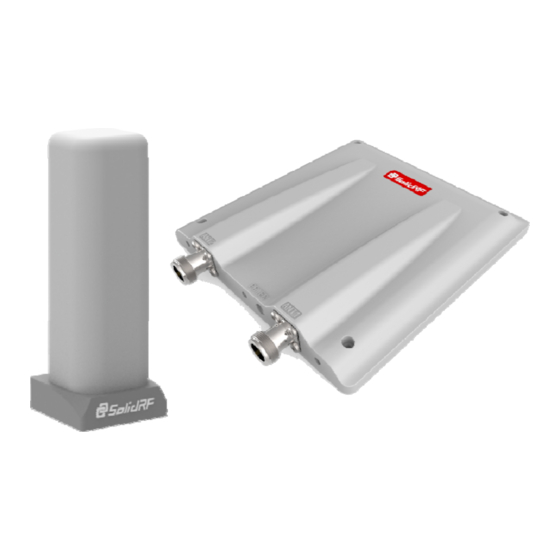
Page 2: Product Diagram
Product Diagram INDOOR UNIT Cable Connector OUTDOOR UNIT Package Contents Package Contents C bl C Cable Connector • Outdoor Unit • Indoor Unit • LM240 Cables: 1 x 45 feet • Power Adapter Indoor Unit Outdoor Unit LM240 Cable Power Adapter Features • Greatly reduces dropped calls, extends signal range, and increases data rates • Allows multiple mobile devices to be used simultaneously • Oscillation (or interference) detection and automatic shutdown • Overload protection circuit – protects cell towers from being overloaded • Amplifies signal both to and from the cell tower Amplifies signal both to and from the cell tower •... -
Page 3: Test Installation
Test Installation We STRONGLY recommends doing a soft install before the formal installation. Doing a test installation of a cell phone booster allows to get best optimal system setup. Step1: Find the strongest signal, setup outdoor antenna with cable screwed Affected by terrain and signal propagation characteristics. More higher of the outdoor antenna will get better signal. Find the best signal around the house by checking the bars of the cell phone. Setup the outdoor antenna on the top of building and connect the cable. Find a cell tower nearby! There are a bunch of resource online, here are some third party websites and app recommended. SolidRF does NOT guarantee the accuracy or completeness on Third Party content For Canada website: www.cellmapper.net app: TowerLocator(iPhone or Android) For U.S. websites: www.cellmapper.net www.cellreception.com/towers www.antennasearch.com Step2: Find a suitable place inside home for booster nearby the power socket Minimum Required Separation Distance Between Indoor And Outdoor Antenna: 6 meters (20 ft ) horizontal distance 6 meters (20 ft ) horizontal distance 4 meters (13 ft ) vertical distance(As far as ... - Page 4 Step3: Introduce cables into room Attention: Don’t excessive bending of the cable, otherwise it will be damaged and loss functions damaged and loss functions. Step4: Setup booster 1. Connect cable to outside connecter make s re pin of the connecter, make sure pin of the cable head smooth import connecter’s socket, and then screw well till the end; 2. Plug in power cord; Step5: Power on and evaluate effects 1. Power on booster; 2. Observe the flashing status of “ALARM” lights; 3. If the lights lit 1 second and then goes out, that means all the test installation is correct; 4. Now check your cell phone to see how about the signal strength improved; improved; 5. If light is blinking, please read the trouble shooting part of this ...
- Page 5 The Formal Installation OUTDOOR Unit INSTALLATION a. Choose right position: 30 cm away from any other metallic objects, and 100 cm away from any windows b. Mount the antenna as the picture shows t th c. Connect the cable to the outdoor antenna • Make sure connectors are well screwed in • Seal the connectors with glued tape...
-
Page 6: Recommended Installation Position
Recommended Installation Position ARRANGE BOOSTER a. Choose right position • Be sure to be far from any heat source • In a ventilated dry place, temperature range should be from ‐ 25 to +50 b. Mount the booster as the picture shows Technical Specification LTE Cellular PCS AWS (band 4) (band 12/17) (band 13) ( band5) (band 2/25) Frequency Uplink 698‐716 776‐787 824‐849 1850‐1915 1710‐1755 (MHz) Downlink 728‐746 746‐757 869‐894 1930‐1995 2110‐2155 Noise figure <5dB In‐band Flatness... - Page 7 ATTENTION: Self Oscillation We strongly recommend it must achieve the Minimum Required Separation Distance for the installation The improper installation could result in possible Self Oscillation installation. The improper installation could result in possible Self Oscillation. Minimum Required Separation Distance (MRSD):6 meters (20 ft ) distance and 4 meters ( 13 ft ) vertical height distance. What is Self Oscillation: Antennas Installation Recommended When the antennas are too close, they could pick up each others signals, creating a feedback loop condition, which is called Self Oscillation. ≤ 90° By FCC regulations, the cell phone booster would automatically detect this condition and immediately shut down to prevent Self Oscillation from damaging the cellular network. (see TroubleShooting Booklet) How to correct Self Oscillation: Antennas Installation Prohibited If the booster detects Self Oscillation, it will not operate until the condition is will not operate until the condition is ...
-
Page 8: Quick Troubleshooting
The booster outside unit, include the amplifier and the outside antenna have an integrated design. Each are waterproof and no matter rain, snow or fog, they will work properly. However extreme hot or cold temperatures may cause problems to the booster. Optimal functioning will occur from ‐ 20 to +50 . Too high or low temperatures beyond this range will cause the booster to lower output power to avoid damage. If you can not fix the problem please contact the technical support or the reseller If you can not fix the problem, please contact the technical support or the reseller. SolidRF Technical Support: Support@SolidRF.ca Find Strongest Signal Use Cell Phone Only: • Check the signal indicator on the cell phone display, it takes up to 30 seconds to reset a new reading. Or place calls from several locations outside the building. • Read signal strength with numerical value (Smart Phone Only): iPhone: Dial *3001#12345#* then tap the CALL button, a negative number in the upper left corner. Android Phone: Go to Setting – About Phone – Status (SIM Status) – Signal Strength It would a negative number instead of the five dots, the range is from ‐120 (weak) to ‐65 (strong) Use Cell Phone During Test Installation:... - Page 10 FCC Statement:...
- Page 11 ISEDC Statement: Safety Guidelines To uphold network protection standards and ensure compliance, all active cellular devices must maintain a separation distance of at least six feet between the inside unit antenna and outside unit antenna and at least four feet of separation distance from the inside unit. Use only the power supply provided in this package. Use of a non‐SolidRF product or accessory may result in damage to the equipment or components of the equipment. The inside unit is designed for use in an indoor, temperature‐controlled components of the equipment. The inside unit is designed for use in an indoor, temperature controlled environment (less than 100 degrees Fahrenheit). It is not intended for use in attics or similar locations where temperatures may be in excess of that range. RF Safety Warning: Any antenna used with this device must be located at least 8 inches from all persons. ISED CPC‐2‐1‐05 — Zone Enhancers ‐ Spectrum management and telecommunications http://www.ic.gc.ca/eic/site/smt‐gst.nsf/eng/sf08942.html Mobile phone is the minimum distance to use indoor antenna...
-
Page 12: Antenna Kitting Information
SR‐21300100 3dBi 3dBi 3dBi 3dBi 3dBi 3dBi 3 5dBi 3.5dBi 3 5dBi\3 5dBi 3.5dBi\3.5dBi Shenzhen Dachi Communications D hi C i ti Co., Ltd. Lightning Protector ACC010101 0.1 dB 0.1 dB 0.1 dB 0.18dB 0.16dB\0.2dB Shenzhen Dachi Communications Co., Ltd. All equivalent antennas and cables are suitable for use with the SolidRF booster. ...
Need help?
Do you have a question about the TRUE5-A and is the answer not in the manual?
Questions and answers