Table of Contents
Advertisement
Quick Links
Instructions
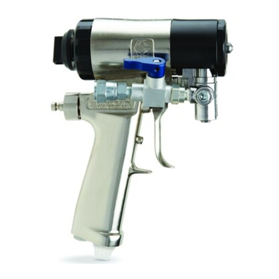
Fusion
For plural component, impingement mix air purge spray gun with ClearShot
technology. For professional use only.
For use with non-flammable foam and polyurea. Not for use in explosive atmospheres.
3500 psi (24.5 MPa, 245 bar) Maximum Fluid Working Pressure
80-130 psi (0.56-0.9 MPa, 5.6-9.0 bar) Air Inlet Pressure Range
200° F (94° C) Maximum Fluid Temperature
Important Safety Instructions
Read all warnings and instructions in this
manual. Save these instructions.
See page 4 for model information.
™
CS
312666W
EN
™
Liquid
TI11323a
Advertisement
Table of Contents
Troubleshooting

Related Manuals for Graco Fusion CS Series


Summary of Contents for Graco Fusion CS Series
- Page 1 Instructions ™ Fusion 312666W ™ For plural component, impingement mix air purge spray gun with ClearShot Liquid technology. For professional use only. For use with non-flammable foam and polyurea. Not for use in explosive atmospheres. 3500 psi (24.5 MPa, 245 bar) Maximum Fluid Working Pressure 80-130 psi (0.56-0.9 MPa, 5.6-9.0 bar) Air Inlet Pressure Range 200°...
-
Page 2: Table Of Contents
Clean or Replace Front Cover and Retainer . . . 25 Graco Information ......60 Clean Breather Plug ..... 25 Clean Fluid Manifold . -
Page 3: Related Manuals
Related Manuals Related Manuals The following manuals are for accessories used with the Fusion CS spray gun. Visit www.graco.com for the most current manual revisions. Description Manual English 309572 Power-Lock™ Heated Hose, Instructions - Parts Manual 309963 Solvent Flush Kits, Instructions -... -
Page 4: Models/Mix Chamber Selection Guide
Models/Mix Chamber Selection Guide Models/Mix Chamber Selection Guide Round Pattern Guns Mix Chamber Impingement Gun Kit, Port Size Equivalent Seal Series Part in. (mm) Size Material CS20RD, B RD2020 0.020 (0.50) -000 CS00RD, B RD0000 0.029 (0.70) CS01RD, B RD0101 0.042 (1.00) CS02RD, B RD0202... -
Page 5: Flat Pattern Guns
Models/Mix Chamber Selection Guide Flat Pattern Guns Mix Chamber Flat Tip Gun Kit, Impingement Equivalent Pattern Size Orifice Size Series Part Port Size in. (mm) Size Part in. (mm) in. (mm) CS20F1, B FL2020 0.020 (0.50) -000 FT0424 8-10 (203-254) 0.024 (0.61) CS20F2, B FL2020... -
Page 6: Wide Round Pattern Gun
Models/Mix Chamber Selection Guide Table 2: Flat Pattern Gun Flow Rate (11.4) 2.25 (8.55) (5.7) 0.75 (2.85) 1000 1500 2000 2500 3000 3500 (3.5, 35) (6.9, 69) (10.3, 103) (13.8, 138) (17.4, 172.4) (20.7, 207) (24.1, 241) PRESSURE in psi (MPa, bar) Wide Round Pattern Gun Mix Chamber Pattern Diameter at... -
Page 7: Warnings
Warnings Warnings The following warnings are for the setup, use, grounding, maintenance, and repair of this equipment. The exclamation point symbol alerts you to a general warning and the hazard symbol refers to procedure-specific risk. Refer back to these warnings. Additional, product-specific warnings may be found throughout the body of this manual where applicable. - Page 8 Warnings WARNING FIRE AND EXPLOSION HAZARD Flammable fumes, such as solvent and paint fumes, in work area can ignite or explode. To help prevent fire and explosion: • Use equipment only in well ventilated area. • Eliminate all ignition sources; such as pilot lights, cigarettes, portable electric lamps, and plastic drop cloths (potential static arc).
-
Page 9: Important Isocyanate (Iso) Information
Important Isocyanate (ISO) Information Important Isocyanate (ISO) Information Isocyanates (ISO) are catalysts used in two component materials. Isocyanate Conditions Spraying or dispensing fluids that contain isocyanates creates potentially harmful mists, vapors, and atomized particulates. • Read and understand the fluid manufacturer’s warnings and Safety Data Sheet (SDS) to know specific hazards and precautions related to isocyanates. -
Page 10: Material Self-Ignition
Important Isocyanate (ISO) Information Material Self-ignition Moisture Sensitivity of Isocyanates Exposure to moisture (such as humidity) will cause ISO to partially cure, forming small, Some materials may become self-igniting if applied hard, abrasive crystal that become suspended too thick. Read material manufacturer’s warnings in the fluid. -
Page 11: Changing Materials
ClearShot Liquid Changing Materials NOTICE Changing the material types used in your equipment requires special attention to avoid equipment damage and downtime. • When changing materials, flush the equipment multiple times to ensure it is thoroughly clean. • Always clean the fluid inlet strainers after flushing. •... -
Page 12: Overall View
Overall View Overall View TI11324a Key: A A Side Fluid Valve (ISO) S Fluid Inlet Swivels (A Side Shown) B B Side Fluid Valve (RESIN) (not shown) T Trigger C Front Cover Retainer U Front Cover D Air Line Quick Coupler V Gun Air Whip Hose E Breather Plug W Air Valve... -
Page 13: Grounding
Check your local electrical code and proportioner manual for detailed grounding instructions. Ground the spray gun through connection to a Disengaged Graco-approved grounded fluid supply hose. Piston Safety Lock TI12240a Engage piston safety lock whenever you stop spraying to avoid accidental triggering. -
Page 14: Remove Front Cover
Remove Front Cover Remove Front Cover Loss of Air Pressure In event of loss of air pressure, gun will continue to spray. To shut off gun, do one of the following: 1. Follow Pressure Relief Procedure, page • Push in piston safety lock, see page 13. •... -
Page 15: Setup
Setup Setup 1. Close fluid valves A and B. c. Close fluid valves and retighten fluid manifold check valves. TI11328a 2. Connect A (ISO) and B (RESIN) fluid hoses TI11337a to fluid manifold. 4. Engage piston safety lock, page 13. 5. -
Page 16: Shutdown
Shutdown 9. Disengage piston safety lock, page 13. 14. Disengage piston safety lock, page 13. TI12240a TI12240a . 10 . 13 10. Trigger gun to check for full mix chamber 15. Test spray onto cardboard. Adjust pressure travel and to prime ClearShot Liquid dosing and temperature to get desired results. -
Page 17: Pressure Relief Procedure
Pressure Relief Procedure Pressure Relief Procedure 3. Disengage piston safety lock, page 13. 1. Engage piston safety lock, page 13. TI12240a . 17 4. Trigger gun onto cardboard or into waste TI11326a . 15 container to relieve pressure. CAUTION Air supply is required for gun actuation. Do not disconnect gun air supply until fluid pressure is relieved. -
Page 18: Optional Hose Position
Optional Hose Position Optional Hose Position Fluid inlet swivel fittings point to rear. If 3. Disconnect fluid hoses from inlet swivels desired, these positions can be changed so (A, B). Remove fluid valve assemblies. hoses point downward. Remove plugs from optional inlets (P). CAUTION To prevent cross-contamination of gun’s wetted parts, do not interchange A... -
Page 19: Flat Spray Tips
Flat Spray Tips Flat Spray Tips 1. Follow Pressure Relief Procedure, page c. Assemble o-ring (47), tip (21), and tip retainer (46) to front of mix chamber (14). 2. Unscrew and remove front cover retainer (C). 8. Reposition tip horizontally or vertically, or install different tip size. -
Page 20: Variable Flow
Variable Flow Variable Flow Operation Change Variable Flow Adjustment Knob NOTE: The variable flow feature is designed to provide immediate adjustment between a full 1. Turn air valve (W) OFF. flow pattern (determined by mix chamber size) and a user defined reduced flow pattern. 2. - Page 21 Variable Flow 3. To increase variable flow: push in and 4. Turn air valve ON, and open fluid valves. turn variable flow knob counterclockwise. Verify that flow selector knob is set to the variable flow position. See F . 25. To decrease variable flow: push in and 5.
-
Page 22: Clearshot Liquid Cartridge Installation/Removal
ClearShot Liquid Cartridge Installation/Removal ClearShot Liquid Cartridge Installation/Removal NOTE: If ClearShot Liquid cartridge removal or 3. Insert cartridge into gun handle. Ensure installation is difficult, lubricate cartridge cartridge tabs are aligned correctly with o-rings and/or cartridge bore with a few drops cartridge tab recesses in gun handle. -
Page 23: Remove Clearshot Liquid Cartridge
ClearShot Liquid Cartridge Installation/Removal Remove ClearShot Liquid Troubleshooting Cartridge For ClearShot Liquid cartridge troubleshooting, see Troubleshooting on page 30. 1. Follow Pressure Relief Procedure, page 2. Turn air valve (W) OFF. 3. Push in and turn cartridge 1/4 turn counterclockwise (viewed from bottom). TI11338a . -
Page 24: Maintenance
Maintenance Maintenance Supplied Tool Kit As Needed • Hex Nut Driver; 5/16 1. Clean Outside of Gun, page 25. 2. Clean Mix Chamber Nozzle, page 27, a • Screwdriver; 1/8 blade minimum of once a day. • Nozzle Drill Bit; various sizes depending on 3. -
Page 25: Flush Gun
Maintenance Flush Gun Clean Outside of Gun Wipe off outside of gun with compatible solvent. Use N-Methylpyrrolidone (NMP), Dynasolve CU-6, Dzolv, or an equivalent to soften cured material. 1. Follow Pressure Relief Procedure, page CAUTION These solvents are not recommended for 2. -
Page 26: Clean Fluid Manifold
Maintenance Clean Fluid Manifold 3. Remove fluid screens by unthreading them from fluid manifold. Clean fluid manifold fluid ports with compatible solvent and brush whenever removed from CAUTION gun. Do not damage the internal sealing To prevent cross-contamination of the check surfaces. -
Page 27: Clean Mix Chamber Nozzle
Maintenance Clean Mix Chamber Nozzle 2. Refer to Table 1. Also see identification chart under Drill Bit Kits, page 53. Use 1. Engage piston safety lock, page 13. appropriate size drill bit to clean mix chamber nozzle (N). TI11326a . 37 TI12090a . -
Page 28: Clean Passages
Maintenance Clean Passages Clean Impingement Ports If necessary, clean out passages in fluid 1. Follow Pressure Relief Procedure, page housing and handle with drill bits. All drill bits are available in an accessory kit. Order kit 2. Disconnect air (D) and remove fluid 256526 for ClearShot Handle Drill Kit;... - Page 29 Maintenance 5. Loosen A and B side seals two turns. Table 2: Impingement Port Drill Bit Sizes Impingement Counter-bore 6. Pull out mix chamber from back of fluid Chamber Port (IP) Drill (CB) Drill Bit housing. See Table 2 for appropriate size Bit Size in.
-
Page 30: Troubleshooting
Troubleshooting Troubleshooting 1. Follow Pressure Relief Procedure, page CAUTION 17, before checking or repairing gun. To prevent cross-contamination of gun’s wetted parts, do not interchange A 2. Check all possible problems and causes component (isocyanate) and B component before disassembling gun. (resin) parts. - Page 31 Troubleshooting PROBLEM CAUSE SOLUTION Leakage between flat tip and mix Tip not seated properly. Reassemble. See Flat Spray chamber. Tips, page 19. Damaged/missing o-ring (47). Replace. See Flat Spray Tips, page 19. Pressure imbalance. Plugged impingement ports. Clean Impingement Ports, page Plugged check valves (44, 45).
- Page 32 Troubleshooting PROBLEM CAUSE SOLUTION Steady air leakage from muffler. Damaged air valve o-rings (4d). Replace. See Air Valve, page 43. Damaged piston o-rings (4a, 4c). Replace. See Piston, page 41. Air leakage from front air valve. Damaged air valve o-rings (4d). Replace.
-
Page 33: Theory Of Operation
Theory of Operation Theory of Operation Gun Triggered (Fluid Spraying) Gun Detriggered (Air Purging) Mix chamber (14) moves back, shutting off Mix chamber (14) moves forward, shutting off purge air flow. Impingement ports (IP) align fluid flow. Impingement ports (IP) open to air with fluid ports of side seals (42, 43), allowing chamber (AC), allowing purge air to flow fluid to flow through mix chamber nozzle (N). -
Page 34: Cutaway View
Theory of Operation Cutaway View 4 (Piston Assembly; see page 44) 2 (Fluid Housing Assembly; see page 1 (Hose Manifold Assembly; see page 48) TI12091a 312666W... -
Page 35: Repair
Repair Repair Tools Required 4. Unscrew and remove front cover retainer (C). Tools required to complete gun repair 5. Remove front cover (U). procedures: • adjustable wrench • flat head screwdriver (included) • 5/16 hex nut driver (included) Lubrication See page 55 to order lubricant. Liberally lubricate all o-rings, seals, and threads. -
Page 36: Attach Front End
Repair Attach Front End 4. Turn fluid housing 1/4 turn clockwise to engage slots. Proper attachment of front end is critical. Do not operate gun if front end is loose or not snug against handle. 1. Engage piston safety lock, page 13. TI12094d . -
Page 37: Mix Chamber And Side Seal Assemblies
Repair Mix Chamber and Side Seal 5. Remove Front End, page 35. Assemblies CAUTION To prevent cross-contamination of side seal See Models/Mix Chamber Selection Guide, assemblies, do not interchange A page 4, for available mix chamber sizes. component and B component parts. The A component assembly is marked with an A. - Page 38 Repair 8. Apply thin coat of lubricant to mix chamber 11. Line up tabs on seal (42c) and seal housing (14). Install mix chamber. Etched A and (42a); insert seal into housing. Push down notch must be on same side as A on fluid on seal and turn to lock in place.
- Page 39 Repair 12. Check for proper spring (42b) operation, 13. Liberally lubricate and reinstall side seal and that the seal (42c) rotates slightly in the assemblies (42, 43). Use hex nut driver to seal housing (42a) detents. tighten. When the seal is installed correctly the spring will be flexible and all four cross holes of the seal will be completely visible.
-
Page 40: Check Valves
Repair Check Valves CAUTION To prevent cross-contamination of the check 1. Follow Pressure Relief Procedure, page valves, do not interchange A component and B component parts. The A component check valve is marked with an A. 2. Remove fluid manifold (M). Leave air connected. -
Page 41: Piston
Repair Piston 7. Clean and inspect all parts. Thoroughly inspect o-rings (44e, 44f). Press on ball (44b) to test check valve for proper 1. Follow Pressure Relief Procedure, page movement and spring action. Replace individual check valve parts as needed. 2. - Page 42 Repair 5. Push piston shaft to remove piston (4b). 11. Reinstall piston. Shaft is keyed for proper Inspect piston o-ring (4c) and shaft o-rings assembly. Push firmly to seat piston. (4a). TI12102a TI12101a . 61 . 60 12. Install variable flow adjustment knob (X). 6.
-
Page 43: Air Valve
Repair Air Valve 4. Liberally lubricate o-rings and reassemble. Torque plug (13) to 25-135 in-lb (14-15 1. Follow Pressure Relief Procedure, page N•m). 5. Attach fluid manifold (M). Connect air (D). 2. Disconnect air (D) and remove fluid Return gun to service. manifold (M). -
Page 44: Parts
Parts Parts Seal Assembly (42) Detail Apply light coating of Fusion grease (31). Apply sealant to threads. Torque to 20-30 in-lb (2.3-3.4 N•m). Torque to 35-40 in-lb (4.0-4.5 N•m). 4d, 4e, 4f Disassembly requires careful application of heat to loosen TI12098b threadlocker. - Page 45 Parts Parts Ref. Part Description Qty. 117485 SPRING, compression Ref. Part Description Qty. 256455 VALVE, spool; includes 15 256466 MANIFOLD, hose, assy. 256414 RETAINER, cover (pack of MANIFOLD 15B221 BOLT; 5/16-24 256415 COVER, front, round, tip 100139 PLUG, pipe (pack of 5) 117634 SWIVEL, union;...
- Page 46 Parts Replacement Danger and Warning labels, Ref. Part Description Qty. tags, and cards are available at no cost. 257422 KIT, valve, check, a side; includes 44a-44f † Not shown. 257427 HOUSING, check valve, a side (pack of 10) ...
- Page 47 Parts Wide and Round Pattern Models Varying Convert Round Pattern to Flat Pattern Parts Table To convert a round pattern gun to a flat pattern gun, order the following parts. Reference Number Model Ref. Part Description Qty. CS00WD Order Kit WD0000 FLxxxx CHAMBER, mix;...
- Page 48 Parts Detail Views 2-Hose Fluid Manifold (1) Detail Flat Pattern Detail TI12106a Supplied Tools TI12107c 25-27 TI3870a Flush Manifold Detail Fluid Inlet Cover Detail TI12108a TI12197a Apply lubricant to seals. Apply sealant to threads. 312666W...
-
Page 49: Mix Chamber Kits
Parts Mix Chamber Kits Round Pattern Mix Chamber Kits Pattern Impinge- Diameter at 24 Chamber Nozzle ment Port Counter- in. (609.6 mm) Nozzle Drill Bit Impinge- Drill Bit bore Drill Bit to target in (includes Orifice Size, ment Port Size, in. Counter- Size, (mm) -
Page 50: Flat Tip Kits
Parts Flat Pattern Mix Chamber Kits Impinge- Chamber Kit Nozzle ment Port Counter- (includes Ref. Nozzle Drill Bit Impinge- Drill Bit bore Drill drill bits and 47†, Orifice Size, ment Port Size, in. Counter- Bit Size, o-ring) O-ring Size in. (mm) Size (mm) bore Size... -
Page 51: O-Ring Repair Kits
Parts O-ring Repair Kits The following table indicates the specific o-ring(s) reference number and quantity included in each o-ring kit. Quantity by Reference Number 51b, 42d, 42e, 44e, 44f, 256490 Complete Kit 256467 Side Seal 278933 Side Seal Only 256468 Side Seal Housing 256640... -
Page 52: Check Valve Filter Screen Kits
Parts Complete O-ring Kit Placement Guide Each o-ring in kit 256490 is labeled by the reference number. See the table entry for 256490 in O-ring Repair Kits on page 51 for the quantity of each. 42d, 44e 43d, 45e 42e, 43e 44f, 45f Check Valve Filter Screen Kits... -
Page 53: Drill Bit Kits
Parts Drill Bit Kits For cleaning gun ports and orifices. Illustrations are actual size for comparison. NOTE: Not all sizes are used with every gun model. Drill Bit Size Kit Part Qty. Illustration nominal 249115 0.125 3.18 246623 0.116 2.90 246810 7/64 0.109... - Page 54 Parts Drill Bit Size Kit Part Qty. Illustration nominal 246629 0.042 1.07 246808 0.040 1.02 248640 0.039 0.99 248618 0.037 0.94 248891 0.033 0.84 246807 0.032 0.81 246630 0.029 0.74 248892 0.028 0.71 246815 0.024 0.61 276984 0.023 0.57 246631 0.020 0.51 246816...
-
Page 55: Accessories
256385 Package of 5 plastic covers 244914 Covers 256386 Package of 1 aluminum covers Keeps gun clean while spraying. Pack of 10. Lubricant for Gun Rebuild 248279, 4 oz (113 gram) [10] High adhesion, water resistant, lithium-based lubricant. MSDS sheet available at www.graco.com. 312666W... -
Page 56: Solvent Flush Canister Kit
Accessories Solvent Flush Canister Kit Circulation Manifold 256510, 1 qt (0.95 liter) Solvent Cup 256566 Includes flushing manifold to flush gun with Attach to gun fluid manifold to enable solvent. Portable for remote flushing. See preheating of hose. See manual 313058. manual 309963. -
Page 57: Gun And Palm Grips
Palm Grips to maximize the comfort and anti-fatigue properties and minimize the applicator's grip strength. Gun Grip Kit Graco Gun Grips are designed to be used on ® ® Fusion A, CS, or Probler P2 Guns. -
Page 58: Repair Kit
Accessories Repair Kit 24X573 Keep bulk spare parts on-hand to rebuild Fusion CS gun. Packaged in convenient carry case. Repair Kit Contents 312666W... -
Page 59: Technical Specifications
Technical Specifications Technical Specifications Fusion CS Metric Maximum Fluid Working Pressure 3500 psi 24.5 MPa, 245 bar Minimum Air Inlet Pressure 80 psi 0.56 MPa, 5.6 bar Maximum Air Inlet Pressure 130 psi 0.9 MPa, 9 bar Air Flow Range See chart below Maximum Fluid Temperature 200°... -
Page 60: Graco Standard Warranty
With the exception of any special, extended, or limited warranty published by Graco, Graco will, for a period of twelve months from the date of sale, repair or replace any part of the equipment determined by Graco to be defective.
Need help?
Do you have a question about the Fusion CS Series and is the answer not in the manual?
Questions and answers