Table of Contents
Advertisement
Quick Links
Instructions-Parts
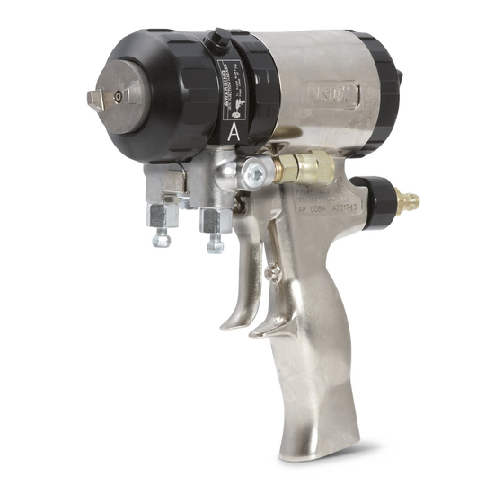
Solvent Purge Plural Component Gun
For use with non-flammable foam and polyurea. For professional use
only. Not for use in explosive atmospheres.
Important Safety Instructions
Read all warnings and instructions in this manual.
Save these instructions.
248597, Series A
Solvent Purge Manual Spray Gun
248647, Series B
Machine Mount Spray Valve with Manual Solvent Purge
248603, Series A
Standard Mechanical Purge Conversion Kit
3500 psi (24.2 MPa, 242 bar) Maximum Fluid Working Pressure
80-130 psi (0.55-0.9 MPa, 5.5-9.1 bar) Air Inlet Pressure Range
200°F (94°C) Maximum Fluid Temperature
3500 psi (24.2 MPa, 242 bar) Maximum Solvent Working Pressure
TI5006c
310648P
EN
TI4965b
II 2 G
Advertisement
Table of Contents

Related Manuals for Graco Fusion


Summary of Contents for Graco Fusion
- Page 1 Instructions-Parts 310648P Solvent Purge Plural Component Gun For use with non-flammable foam and polyurea. For professional use only. Not for use in explosive atmospheres. Important Safety Instructions Read all warnings and instructions in this manual. Save these instructions. 248597, Series A Solvent Purge Manual Spray Gun 248647, Series B Machine Mount Spray Valve with Manual Solvent Purge...
-
Page 2: Table Of Contents
Flush Gun ......24 Graco Information ......56 Clean Outside of Gun . -
Page 3: Manual Conventions
Manual Conventions Manual Conventions Warning Caution CAUTION WARNING A caution alerts you to possible equipment damage or destruction if you do not follow instructions. Note A warning alerts you to possible serious injury or death if you do not follow instructions. A note indicates additional helpful information. - Page 4 Warning WARNING PERSONAL PROTECTIVE EQUIPMENT Always wear appropriate personal protective equipment and cover all skin when spraying, servicing equipment, or when in the work area. Protective equipment helps prevent serious injury, including long-term exposure; inhalation of toxic fumes, mists or vapors; allergic reaction; burns; eye injury and hearing loss.
- Page 5 Misuse can cause serious injury or death. • For professional use only. • Use equipment only for its intended purpose. Call your Graco distributor for information. • Read manuals, warnings, tags, and labels before operating equipment. Follow instructions. • Check equipment daily. Repair or replace worn or damaged parts immediately.
-
Page 6: Overall View
Overall View Overall View TI4966b Key: A Side Fluid Valve (ISO) Optional Fluid Inlets (A Side Shown) B Side Fluid Valve (RESIN) Lock Ring Air Cap Fluid Inlet Swivels (A Side Shown) Air Line Quick Coupler Trigger Muffler Gun Air Whip Hose Fluid Housing Air Valve Gun Fluid Manifold... -
Page 7: Important Isocyanate (Iso) Information
Important Isocyanate (ISO) Information Important Isocyanate (ISO) Information Isocyanates (ISO) are catalysts used in two component materials. Isocyanate Conditions Spraying or dispensing fluids that contain isocyanates creates potentially harmful mists, vapors, and atom- ized particulates. • Read and understand the fluid manufacturer’s warnings and Safety Data Sheet (SDS) to know specific hazards and precautions related to isocyanates. -
Page 8: Material Self-Ignition
Important Isocyanate (ISO) Information For all applications except spray foam Keep Components A and B Separate Spraying or dispensing fluids that contain isocyanates creates potentially harmful mists, vapors, and atomized Cross-contamination can result in cured material in fluid particulates. lines which could cause serious injury or damage equipment. -
Page 9: Foam Resins With 245 Fa Blowing Agents
Check your local electrical code and proportioner man- Changing Materials ual for detailed grounding instructions. Solvent line must be Graco approved grounded hose. NOTICE Changing the material types used in your equipment Primary ground is through the grounded solvent supply requires special attention to avoid equipment damage hose. -
Page 10: Piston Safety Lock
Piston Safety Lock Piston Safety Lock Loss of Air Pressure Engage piston safety lock whenever you stop spray- In event of loss of air pressure while gun is triggered, ing, to avoid accidental triggering. gun will continue to spray. To shut off gun, do one of the following: •... -
Page 11: Conversion Kit 248603
Conversion Kit 248603 Conversion Kit 248603 A Standard Mechanical Purge Gun can be converted into a Solvent Purge Gun with this kit. Liberally lubricate piston o-rings. Install spacer (61) onto piston assembly. Reinstall piston. Shaft is keyed for proper assembly. Push firmly to seat pis- Relieve pressure. -
Page 12: Mounting An Automatic Gun
Mounting an Automatic Gun Mounting an Automatic Gun Mounting to a rod Mounting to a stationary support robotic arm To mount gun to stationary support or robot arm, see To mount the gun on a 1/2 in. diameter rod, insert mounting hole dimensions, page 53. -
Page 13: Setup
Setup Setup Read Hand Drilling of Mix Modules, page 15, Engage piston safety lock (L), page 10. before performing setup procedure. Assemble gaskets (40c), static mixer assembly (40), o-ring (40d), adapter (41), and RAC tip and guard (9, 63) assembly to fluid housing on front TI3850a end of gun. - Page 14 To adjust purge rod position, follow piston and Disengage piston safety lock (L), page 10. purge rod disassembly instruction on page 39. Attach Graco approved grounded fluid supply hose to solvent inlet (Y). Make sure solvent purge valve (V) is closed before TI3849a pressurizing the solvent hose.
-
Page 15: Hand Drilling Of Mix Modules
Locate the larger part side (typically the B [RES] flow at the mix gun port at rear of Polycarballoy Mix Module). Graco only makes 1:1 ratio mix modules. When apply- ing a material that is different than 1:1 it is necessary to Polycarballoy Mix Module cross section. - Page 16 Hand Drilling of Mix Modules Module Port Drill Bit Size When drilling, be careful not to allow bit to come in contact with ID of mix module. The largest drill size that can be used on the XF1313 mix module is #56. To get more flow, Drill Bit Table order a larger mix module: XF3535, XF4747, XF5757...
-
Page 17: Operation
Operation Operation Spraying Turn RAC tip (X) to clean position. To spray, turn RAC tip (X) to spray position. TI5097b TI5096b Hold gun into a grounded metal pail, holding a metal part of fluid manifold firmly to side of pail. Close solvent purge knob (V). -
Page 18: Shutdown
Shutdown Shutdown Daily Shutdown Follow Pressure Relief Procedure, page 19. Flush Gun, page 24. Shutdown for More than a Follow Pressure Relief Procedure, page 19. Flush Gun, page 24. 310648P... -
Page 19: Pressure Relief Procedure
Pressure Relief Procedure Pressure Relief Procedure Turn RAC tip (X) to clean position. WARNING Read warnings, page 5. Relieve pressure before cleaning or repairing gun. Engage piston safety lock (L), page 10. TI5097b Trigger gun onto cardboard or into waste container to relieve pressure. - Page 20 Pressure Relief Procedure Engage piston safety lock (L), page 10. TI3850a WARNING If fluid in the hose and proportioner is still under pres- sure, follow the Pressure Relief Procedure in the pro- portioner manual. To relieve pressure in the hose after the gun is removed, place the fluid manifold over containers, fac- ing away from you.
-
Page 21: Optional Configurations
Optional Configurations Optional Configurations Optional Fluid Manifold Unscrew lock ring (P) until front end of gun is Position loose. Fluid manifold is mounted to bottom of gun, with A side on left, viewed from operator’s position at back of gun. If Rotate fluid housing (F) 180°... -
Page 22: Optional Hose Position
Optional Configurations Optional Hose Position Apply thread sealant to plugs (Z), elbows (AA), and Fluid inlet swivels and air quick disconnect fitting point to male threads of swivels (R). Install elbows (V) in rear. If desired, these positions can be changed so optional inlets (N), facing down. -
Page 23: Maintenance
Applying a light coat of lubricant will make cleaning eas- screens. ier. Lubricate threads and outside of lock ring (11) to ease disassembly. Use Fusion Gun Lubricant 118665. Check that piston safety lock threaded connection As Needed is tight, page 41. -
Page 24: Flush Gun
(AB) in the top mating sur- face. Do not damage the flat sealing surfaces. Cover Solvent Flush Kits 248139 and 248229 are avail- with Fusion Lubricant 118665 if left exposed, to seal out able as accessories. moisture. -
Page 25: Clean Slip-Fit Polycarballoy Mix Module
Maintenance Clean Slip-Fit Polycarballoy Mix Module Follow Pressure Relief Procedure, page 19. Flush Gun, page 24. TI3863a . 1. Cleaning Component A (ISO) Ports Remove mix module, page 34. CAUTION To avoid damaging mix module, do not force drill bits when cleaning impingement ports. -
Page 26: Troubleshooting
Troubleshooting Troubleshooting Follow Pressure Relief Procedure, page 19, before checking or repairing gun. Check all possible problems and causes before disassembling gun. CAUTION To prevent cross-contamination of the gun’s wetted parts, do not interchange A component (isocyanate) and B component (resin) parts. PROBLEM CAUSE SOLUTION... - Page 27 Troubleshooting PROBLEM CAUSE SOLUTION Fluid does not shut off when fluid Damaged fluid valves (12b). Replace. valves are closed. Air leakage around fluid housing. Damaged or missing o-ring (20). Replace. Air leakage from piston safety lock. Damaged or missing o-rings (18). Replace, page 39.
-
Page 28: Theory Of Operation
Troubleshooting Theory of Operation Gun Triggered (Fluid Spraying) Purge rod (31) moves back, opening impingement ports (IP). Components A and B combine in mix module (39). Fluid mixes in static mixer chamber (40) and sprays from RAC tip (9). Fluid ti5099 Gun Detriggered (Mechanical and Solvent Purging) Purge rod (31) moves forward, closing impingement... -
Page 29: Cutaway View
Troubleshooting Cutaway View TI4992b 310648P... -
Page 30: Repair
TI5002b Lubrication Remove mix module nut (25), using a wrench. Remove front seal (46). Liberally lubricate all o-rings, seals, and threads with Fusion Gun Lubricant, 118665. Lubricate threads and outside of lock ring (11). Disassemble Front End TI4986a WARNING Read warnings, page 5. Proper attachment of front end is critical. - Page 31 Repair Remove mix module (39). Ti3846a CAUTION If lock ring (11) is stuck due to material buildup, do not force it by turning entire front end. Locating tabs (Z) may break off. Soak front of gun in solvent to soften cured material and free lock ring.
-
Page 32: Reassemble Front End
Repair Reassemble Front End CAUTION To prevent damage to purge rod (31), always slide front end straight onto purge rod. Check that o-rings (20, 21) are in position. Liberally lubricate o-rings, threads of lock ring (11) and han- dle (1), and outside of lock ring. Carefully slide front end straight onto purge rod (31). - Page 33 Repair CAUTION Reinstall solvent purge assembly (28). Lubricate Do not overtighten mix module nut (25). Overtighten- all threads. Install static mixer (40) and RAC tip (9). ing can deform impingement holes and cause slow Tighten with wrench. gun actuation. Lubricate all threads and reassemble mix module nut (25) fingertight.
-
Page 34: Slip-Fit Polycarballoy Mix Module
Repair Slip-Fit Polycarballoy Mix Disengage piston safety lock (L), page 10. Trigger Module and detrigger gun once to release mix module (39) from fluid housing (7). Remove mix module. See page 50 for available Slip-Fit Polycarballoy Mix Engage piston safety lock. Module sizes. - Page 35 Repair CAUTION Reinstall solvent purge assembly (28). Lubricate Do not overtighten mix module nut (25). Overtighten- all threads. Install static mixer (40) and RAC tip ing can deform impingement holes and cause slow and guard (9, 63). Tighten with wrench. gun actuation.
-
Page 36: Rear Rod Seal
Repair Rear Rod Seal Reassemble new rear seal (46) in rear rod seal nut (23). Lubricate threads and install in fluid housing (7) with nut driver. Follow Pressure Relief Procedure, page 19. Reassemble Front End, page 32. Flush Gun, page 24. Attach fluid manifold. -
Page 37: Adjust Rear Rod Seal
Repair Adjust Rear Rod Seal Follow Pressure Relief Procedure, page 19. Remove fluid housing (7) from rod (31). Flush Gun, page 24. Reassemble Front End, page 32. Remove fluid manifold (G). Leave air connected. Attach fluid manifold. Return gun to service. TI4972b Disassemble Front End, page 30. -
Page 38: Check Valves
Repair Check Valves WARNING Before disassembling, press on ball (36c) to test check valve for proper movement and spring Read warnings, page 4. Damaged check valve o-rings action. (36f, 36g) may result in external leakage. Replace o-rings if any damage is seen. Follow Pressure Relief Procedure, page 19. -
Page 39: Piston And Purge Rod
Disconnect air (D) and remove fluid manifold (G). Unscrew rod from piston with nut driver. Inspect o-ring (18). Liberally lubricate with Fusion Gun Lubricant. To reassemble, thread purge rod (31) into piston (32) until rod stops. Spacer (62) acts as a positive stop. - Page 40 Repair Install piston safety lock assembly until bottomed out. TI3847a Reassemble Front End, page 32. Attach fluid manifold. Connect air. Return gun to service. 310648P...
-
Page 41: Piston Safety Lock
Apply medium-strength Loctite or equiv- alent to threads on stop (15) and cap (10), and reassemble. Liberally lubricate o-rings and reassemble. Use Fusion Gun Lubricant 118665. Torque plug (2) to 125-135 in-lb (14-15 N•m). Attach fluid manifold. Connect air. Return gun to service. -
Page 42: Solvent Purge Assembly
Repair Solvent Purge Assembly Reassemble air cap (28b) to housing (28a), then install (28c) and (28d) into housing (28a). Follow Pressure Relief Procedure, page 19. Assemble (28e). Lubricate packings. Slide (28h) over assembled (28e) into groove and lubricate. Flush Gun, page 24. Assemble knob (28f) onto (28e). -
Page 43: Static Mixer Assembly
Repair Static Mixer Assembly Reassemble static mixer assembly (40a-e). Follow Pressure Relief Procedure, page 19. Reassemble RAC tip, guard (9, 63) and static mixer (40) from solvent purge assembly (28). Flush Gun, page 24. 9, 63 Disconnect air (D) and remove fluid manifold (G). TI5033b Attach fluid manifold. - Page 44 Repair 310648P...
-
Page 45: Parts
Parts Parts 248597 and 248647 Solvent Purge Plural Component Spray Guns, and 248603 Conversion Kit TI5034a Static Mixer Assembly TI5035a Solvent Purge Assembly Ref. Part No. Description Qty. 28❖ 248643 SOLVENT PURGE ASSY.; includes items 28a-28m 15E111 . HOUSING 15E130 . CAP, air 113618 . -
Page 46: 248597 Solvent Purge Manual Spray Gun
Parts 248597 Solvent Purge Manual Spray Gun ★ 25 39 †‡ ★ 28❖ ★ ★ ★ ★ ★ ★ 61❖ ★ 62❖ Supplied Tools ‡◆ ‡◆ ‡ †‡ ‡◆ ‡ ‡ ◆†‡ TI3870a †‡ ‡ ‡ ‡ *36g ‡ †‡ *36f †‡... -
Page 47: 248597 Solvent Purge Manual Spray Gun
117635 . SWIVEL, A side; 1/8 npt(m) x 118575 SCREWDRIVER; 1/8 blade no. 5 JIC(f) 15C480 WASHER, wave 15B993 . SPRING, ring, lock 57■ 118665 LUBRICANT, Fusion Gun; 4 oz 15B209 TRIGGER (113 gram) ★ ★ 248136 O-RING, rod stop; package of 6 15D329 STOP, rod ★... -
Page 48: 248647 Machine Mount Spray Valve With Manual Solvent Purge
Parts 248647 Machine Mount Spray Valve with Manual Solvent Purge ★ ★ †‡ ★ ★ ★ ★ ★ ★ 62❖ ★ Check Valve 61❖ (36) Detail ‡ ‡ †‡36b ‡ †‡ ‡ ‡ ‡ ‡ ‡ ‡ †‡ *‡36g †‡36a ‡... -
Page 49: 248647 Machine Mount Spray Valve With Manual Solvent Purge
117642 NUT DRIVER, hex; 5/16 . MANIFOLD 118575 SCREWDRIVER; 1/8 blade † 246356 . VALVE, fluid 57■ 118665 LUBRICANT, Fusion Gun; 4 oz 100139 . PLUG, pipe; 1/8-27 npt (113 gram) ★ 15B221 . BOLT; 5/16-24 15D329 STOP, rod ★... -
Page 50: Slip-Fit Polycarballoy Mix Module Kits
**For further information, see identification chart under Gun Grip Kit Drill Bit Kits, page 51. ® Graco Gun Grips are designed to be used on Fusion ® **For further information, see identification chart under A, CS, or Probler P2 Guns. -
Page 51: Drill Bit Kits
Parts Drill Bit Kits For cleaning gun ports and orifices and sizing mix module orifices. Illustrations are actual size, for comparison. Not all sizes are used with your gun. Drill Bit Size Kit Part No. Qty in Kit Illustration nominal 246623 0.116 2.90... -
Page 52: Gun Repair Kits
Gun Repair Kits Gun Repair Kits Read the chart left to right and top to bottom to find the quantity of each part in the kits. Ref. Bulk O-ring 246351 248887 Kits, (qty) Check Valve Solvent Purge Gun O-ring Kit Complete O-ring Kit 248136 (6) 248135 (6) -
Page 53: Model 248647 Mounting Dimensions
Model 248647 Mounting Dimensions Model 248647 Mounting Dimensions Measurement Definition in. (mm) 0.73 (18.54) 2 x 1/4-20 1.30 (33.0) 1 (25.4) 0.625 (15.88) 1.06 (26.92) 3 x 1/8 npt 4 x M5 0.127 (3.23) ti4751b 0.625 (15.88) 310648P... -
Page 54: Technical Data
Technical Data Technical Data Category Data Maximum Fluid Working Pressure 3500 psi (24.2 MPa, 242 bar) Minimum Air Inlet Pressure 80 psi (0.55 MPa, 5.5 bar) Maximum Air Inlet Pressure 130 psi (0.9 MPa, 9 bar) Maximum Fluid Temperature 200° F (94° C) Air Inlet Size 1/4 npt Quick Disconnect Nipple Solvent Inlet Size... - Page 55 Technical Data 310648P...
-
Page 56: Graco Standard Warranty
With the exception of any special, extended, or limited warranty published by Graco, Graco will, for a period of twelve months from the date of sale, repair or replace any part of the equipment determined by Graco to be defective.
Need help?
Do you have a question about the Fusion and is the answer not in the manual?
Questions and answers