Graco FinishPro 390 Repair Electrical Manual
Airless/air-assisted sprayer
Hide thumbs
Also See for FinishPro 390:
- Operation (50 pages) ,
- Operation manual (56 pages) ,
- Repair manual (41 pages)
Table of Contents
Advertisement
Quick Links
Airless/Air-Assisted Sprayer
Repair Electrical Manual
FinishPro 395
WARNING
This manual should only be used
by a qualified Service Technician.
FinishPro™ 390/395
ti9026a
3.00
� �
- -
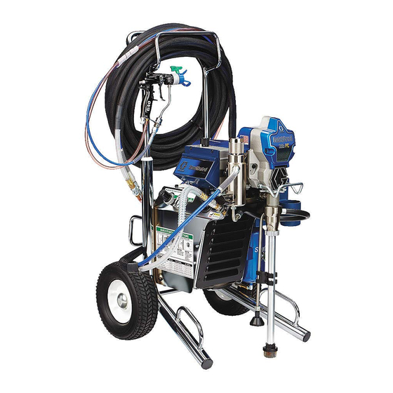
Air Hose
Connection
FinishPro 390
Exhaust Port
First choice when
quality counts.
Rev. B 10/11 /07
Black
Red
Yel
Yel
ti9019a
Advertisement
Table of Contents

Related Manuals for Graco FinishPro 390


Summary of Contents for Graco FinishPro 390
- Page 1 Airless/Air-Assisted Sprayer Repair Electrical Manual First choice when quality counts. Rev. B 10/11 /07 FinishPro 395 3.00 � � Black ti9026a Air Hose Connection FinishPro 390 Exhaust Port ti9019a WARNING This manual should only be used by a qualified Service Technician.
-
Page 2: Table Of Contents
Table of Contents Basic meter terminology and testing procedures....................3-9 Error Code Chart ............................. 26-32 FinishPro 390 ON/OFF Switch Test ............................10 Switch Ladder Diagram............................11 288841Control board: • Airless Motor will not start......................... 12,13 • Airless Motor Test ........................... 14 •... -
Page 3: Basic Meter Terminology And Testing Procedures
BASIC ELECTRICAL TERMINOLOGY In any discussion of electricity, there are three basic terms you will need to understand. CURRENT VOLTAGE RESISTANCE CURRENT: Current is the movement of the electrical charge. Current Flows through the wires from the power source to the load. Current is measured in AMPERES (AMPS, A or I). - Page 4 BASIC ELECTRICAL TERMINOLOGY RESISTANCE: Resistance is anything that causes an opposition to the fl ow of current in a circuit. Resistance is used to control the amount of voltage and/or amperage in a circuit. Resistance is measured in OHMS - Ω. See Figure 3. A common component check would be motor and clutch field windings.
- Page 5 CONTINUITY TESTING Checking “continuity” is one of the most common tests in electrical troubleshooting. Continuity is the ability of a wire or electrical component to conduct current. When you use a continuity tester, you connect a circuit (the continuity tester) that you know works, to a wire or a component that may or may not work.
- Page 6 WIRE CONTINUITY TESTING Continuity testing will “NOT” fi nd wire fragmentation!! Example: 120 Vac input static voltage and drops to 119Vac load voltage. A good piece of wire will carry line and load voltage. Damaged / Fragmented Wire Damaged / Fragmented Wire Pinched Wire 120 Vac input static voltage and drops to 76Vac load voltage.
- Page 7 GROUND TESTING Improper installation or alteration of grounding plug could results in risk of electric shock, fire or explosion that could cause serious injury or death. The other function of the grounding plug is to protect the control board from static build up. If the plug is missing this could cause permanent damage to the control board.
- Page 8 CAPACITOR TESTING: A capacitor is an electrical component that stores electricity. Capacitors are usually used to help start a motor or make a motor run more efficiently. The following instructions can be used to test any capacitor. WARNING! A CAPACITOR CAN SHOCK YOU EVEN WHEN A MACHINE IS UNPLUGGED. NEVER TOUCH CAPACITOR TERMINALS WITH YOUR FINGERS.
- Page 9 RECTIFIER (See Fig. 1) Now we come to the most popular application of the diode: rectifcation. Rectifcation is the conversion of alternating current (AC) to direct current (DC). This almost always involves the use of some device that only allows one-way fl ow of electrons. As we have seen, this is exactly what a diode does.
-
Page 10: Finishpro 390
FinishPro 390 ON/OFF Switch Test Check the connector for the white wires. See step 1.Do you have If ok repair or replace over 100 AC volts? Step 1 110-120 AC the power Cord. Power switch in the Airless Mode. Cord plugged in. -
Page 11: Switch Ladder Diagram
FinishPro™ 390 Switch Ladder Diagram Black Switch Center Control Board Black White White White White Black Black Compressor Power Cord Airless Black Control Board Airless Mode Switch Down Black White White Black Black Compressor Power Cord Air-Assisted Air Assisited Mode Black Control Board Switch Up... -
Page 12: 288841Control Board
FinishPro 390 288841 Control Board Airless Motor will not run See pages 12 for the steps and illustrations. See step 1. See ON/OFF Do you have Switch Test over 100 AC volts? See step 2. Do you have over Replace Control Board. - Page 13 FinishPro 390 261779 Control Board Airless Motor will not run Step 1 Step 2 110-120 AC 110-120 AC Cord plugged in. Cord plugged in. Switch ON. Switch ON. Wires connected Wires connected to control board. to control board. Meter on AC Volts...
-
Page 14: Airless Motor Test
249040 Motor Test 1. Remove the pump pin and try to run the sprayer.If the motor runs check for locked or frozen pump or drive train. If sprayer does not run, go to next step. 2. Set sprayer to OFF and disconnect power to sprayer . 3. -
Page 15: Airless Motor Will Not Shut Off
FinishPro 390 Control Board 261779 Motor will not shut off: Unplug sprayer turn the Unplug sprayer turn the prime/spray valve to the Check the Inlet and Out prime/spray valve to the prime prime position. Plug sprayer valves for a stuck ball, position. -
Page 16: Air Compressor Will Not Start
390 FinishPro Air Compressor will not start. Does the airless See ON/OFF motor run? Switch Test section Step 1 110-120 AC Power switch in the AA Mode. Cord plugged in. See step 1. Do you have Replace the Meter on AC Volts over 100 AC volts? power switch. -
Page 17: Air Compressor Runs But Will Not Build Pressure
390 FinishPro Air Compressor runs but will not build pressure. Connect a test air gauge Is there air coming Is the compressor Is there air coming out of the air to the air hose connector. trying to start? out of the air Pressure Start the compressor. -
Page 18: Finishpro 395
FinishPro 395 ON/OFF Switch Test See pages 18 for the steps and illustrations. Check the connector for the white wires. See step 1.Do you have If ok repair or replace over 100 AC volts? the power Cord. See step 2. Do you have Replace the over 100 AC volts? power switch. - Page 19 FinishPro 395 ON/OFF Switch Test Step 3 Step 1 Step 2 110-120 AC 110-120 AC 110-120 AC Power switch in the Power switch in Power switch in AA Mode. the Airless Mode. the Airless Mode. Blk meter led on the Cord plugged in.
-
Page 20: Switch Ladder Diagram
FinishPro™ 395 Switch Ladder Diagram Switch Center Black Yellow Yellow Black Power Control Board Cord White White Brown Brown Blue Compressor Blue Airless Mode Airless Switch Down Black Yellow Yellow Black Power Control Board Cord White White Brown Brown Blue Compressor Blue Air-Assisted... -
Page 21: 288841Control Board
FinishPro 395 288840 Control Board Airless Motor will not run See page 20 for the steps and illustrations. Remove the control box Have the steps been cover. Turn See ON/OFF followed in the the sprayer Switch Test. (ON/Off Switch Test) section? on. - Page 22 FinishPro 395 288840 Control Board Airless Motor will not run Step 2 Step 1 100 + DC 110-120 AC Cord plugged in. Cord plugged in. Switch ON. Switch ON. Pressure Switch Wires connected. Turned to high. Meter on DC volts. Control Board Control...
-
Page 23: Airless Motor Test
288859 Motor Test 1. Remove the pump pin and try to run the sprayer.If the motor runs check for locked or frozen pump or drive train. If sprayer does not run, go to next step. 2. Set sprayer to OFF and disconnect power to sprayer . 3. -
Page 24: Airless Motor Will Not Shut Off
FinishPro 395 Control Board 288840 Motor will not shut off: Unplug sprayer turn the Unplug sprayer turn the prime/spray valve to the Check the Inlet and Outlet prime/spray valve to the prime valves for a stuck ball, prime position. Plug sprayer position. -
Page 25: Air Compressor Will Not Start
395 FinishPro Air Compressor will not start. Step 1 Does the airless See ON/OFF 110-120 AC Power switch in the motor run? Switch Test section AA Mode. Blk meter led on the Brown wire terminal. Cord plugged in. Meter on AC Volts AA Mode See step 1. -
Page 26: Error Code Chart
395 FinishPro Air Compressor runs but will not build pressure. Is there air coming Is the compressor Connect a test air gauge Is there air coming out of the air trying to start? to the air hose connector. out of the air Pressure (Humming) Start the compressor. - Page 27 FinishPro 395 Error Codes 288840 Control Board Error Codes: CONTROL BOARD GO TO PAGE INDICATION STATUS LIGHT. One Blink when switch Power to board is ok, No RUN command to motor. is turned on. Control is commanding motor to run . Constant on Blinks 2 x repeatedly High pressure signal from transducer.
- Page 28 _ _ _ _ Symptoms: • Sprayer does not run at all • Digital Display shows dashes and Psi icon is not blinking • Control board status light blinks once when switch is turned on but then stays off. What does this mean? Power to board is ok but there is no RUN command to the motor.
- Page 29 Symptoms: • Sprayer does not run at all E=02 • Digital Display shows E=02 • Control board status light blinks 2x repeatedly. What does this mean? The control board is detecting an excessive pressure. The transducer or connections is likely the problem. Troubleshooting Procedure: 1.
- Page 30 Symptoms: • Sprayer does not run at all E=03 • Digital Display shows E=03 • Control board status light blinks 3x repeatedly. What does this mean? The control board is not detecting a pressure signal. The pressure transducer or connections are likely the problem. Troubleshooting Procedure: 1.
- Page 31 Symptoms: • Sprayer does not run at all E=04 • Digital Display shows E=04 • Control board status light blinks 4x repeatedly. What does this mean? Voltage applied to the sprayer is too high. Troubleshooting Procedure: 1. Make sure the sprayer is plugged into the proper AC power source. Less than 138 volts for 120V sprayers and less than 260V for 230V sprayers.
- Page 32 Symptoms: • Sprayer does not run at all E=05 • Digital Display shows E=05 • Control board status light blinks 5x repeatedly. What does this mean? The control is commanding the motor to run but the motor shaft does not rotate. Possibly locked rotor condition, an open connection exists between the motor and control, there is a problem with the motor or control board or the motor amp draw is excessive.
- Page 33 Symptoms: • Sprayer does not run at all E=06 • Digital Display shows E=06 • Control board status light blinks 6x repeatedly. What does this mean? Motor is too hot or motor thermal switch connections are likely the problem. Troubleshooting Procedure: 1.
Need help?
Do you have a question about the FinishPro 390 and is the answer not in the manual?
Questions and answers