Graco Fusion A Series Instructions Manual
Pc spray gun
Hide thumbs
Also See for Fusion A Series:
- Instructions - parts manual (22 pages) ,
- Instructions-parts list manual (56 pages)
Table of Contents
Advertisement
Quick Links
Instructions
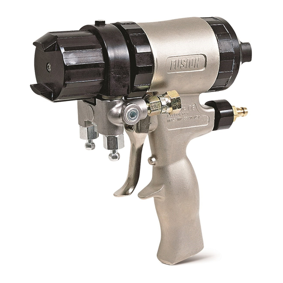
Fusion
Plural component, impingement mix air purge spray gun with ProConnect
for dispensing non-flammable foam and polyurea. For professional use only.
Not approved for use in European explosive atmosphere locations.
3500 psi (24.5 MPa, 245 bar) Maximum Fluid Working
Pressure
80-130 psi (0.56-0.9 MPa, 5.6-9.0 bar) Air Inlet Pressure
Range
200°F (94°C) Maximum Fluid Temperature
See page 4 for model information.
Important Safety Instructions
Read all warnings and instructions in this
manual and in all related manuals before
using the equipment. Save these
instructions.
Important Medical Information
Read the medical alert card provided with
the gun. It contains injection injury
treatment information for a doctor. Keep it
with you when operating the equipment.
®
PC Spray Gun
3A7314B
EN
™
fluid cartridge
Advertisement
Table of Contents


Need help?
Do you have a question about the Fusion A Series and is the answer not in the manual?
Questions and answers