Table of Contents
Advertisement
Repair
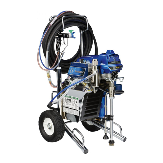
FinishPro II 395/595
Airless/Air-Assisted Sprayer
For the application of architectural paints and coatings.
Not approved for use in explosive atmospheres or hazardous locations.
Maximum Fluid Working Pressure: 3300 psi (227 bar, 22.7 MPa)
Maximum Air Working Pressure: 35 psi (2.4 bar, 0.24 MPa)
Important Safety Instructions
Read all warnings and instructions in this manual,
and in the gun manual. Save these instructions.
Models:
Region
FinishPro II 395
US
Europe CEE 7/7
Europe Multi Cord
UK
Asia/Australia
Related Manuals:
333120
309250
For professional use only.
FinishPro II 595
24U065
24U073
24U067
24U075
24U069
24U077
24U070
---------
24U071
24U071
333182
333154
FinishPro II 395
ti22591a
FinishPro II 595
333126A
EN
ti22592a
Advertisement
Table of Contents

Related Manuals for Graco FinishPro II 395


Summary of Contents for Graco FinishPro II 395
- Page 1 Repair FinishPro II 395/595 333126A Airless/Air-Assisted Sprayer For the application of architectural paints and coatings. For professional use only. Not approved for use in explosive atmospheres or hazardous locations. Maximum Fluid Working Pressure: 3300 psi (227 bar, 22.7 MPa) Maximum Air Working Pressure: 35 psi (2.4 bar, 0.24 MPa)
-
Page 2: Table Of Contents
Motor Replacement ......35 FinishPro II 395 ......35 Motor Replacement . -
Page 3: Warning
Warning Warning The following warnings are for the setup, use, grounding, maintenance, and repair of this equipment. The exclama- tion point symbol alerts you to a general warning and the hazard symbols refer to procedure-specific risks. When these symbols appear in the body of this manual or on warning labels, refer back to these Warnings. Product-specific hazard symbols and warnings not covered in this section may appear throughout the body of this manual where applicable. - Page 4 All parts of the spray sys- tem, including the pump, hose assembly, spray gun, and objects in and around the spray area shall be properly grounded to protect against static discharge and sparks. Use Graco conductive or grounded high-pressure airless paint sprayer hoses.
- Page 5 Check hoses and parts for signs of damage. Replace any damaged hoses or parts. • This system is capable of producing 3300 psi (227 bar, 22.7 MPa) psi. Use Graco replacement parts or accessories that are rated a minimum of 3300 psi (227 bar, 22.7 MPa) psi.
- Page 6 Warning WARNING WARNING WARNING WARNING BURN HAZARD Equipment surfaces and fluid that is heated can become very hot during operation. To avoid severe burns: • Do not touch hot fluid or equipment. MOVING PARTS HAZARD Moving parts can pinch, cut or amputate fingers and other body parts. •...
-
Page 7: Notes
Notes Notes 333126A... -
Page 8: Component Identification
Component Identification Component Identification FinishPro II 395 ti22593a FinishPro II 595 ti22594a 333126A... -
Page 9: Component Identification
Component Identification Component Identification Item Description Drain Tube/Hose Air Hose Connection Prime/Spray Valve Fluid Outlet Air/Fluid Supply Hose Displacement Pump Gun (see manual) Filter Manifold Fluid Pressure Control Power/Function Selector Suction Tube Gun Air Regulator Sprayer Air Pressure Regulator Digital Display Air Pressure Gauge Gun Filter 333126A... -
Page 10: Grounding
Grounding Grounding Extension Cords Ground The equipment must be grounded to reduce the risk of static sparking and electric shock. Electric or static Use an extension cord with an undamaged ground con- sparking can cause fumes to ignite or explode. tact. -
Page 11: Pressure Relief Procedure
Pressure Relief Procedure Pressure Relief Procedure Follow the Pressure Relief Procedure whenever 4. Turn prime valve down. you see this symbol. This equipment stays pressurized until pressure is manually relieved. To help prevent serious injury ti2719a from pressurized fluid, such as skin injection, splashing fluid and moving parts, follow the Pressure If you suspect spray tip or hose is completely clogged, Relief Procedure when you stop spraying and before... -
Page 12: General Repair Information
General Repair Information General Repair Information Flammable materials spilled on hot, bare, motor could To reduce risk of serious injury, including electric shock: cause fire or explosion. To reduce risk of burns, fire or • Do not touch moving or electric parts with fingers or explosion, do not operate sprayer with cover removed. -
Page 13: Troubleshooting
Troubleshooting Troubleshooting What To Check What To Do Problem (If check is OK, go to next check) (When check is not OK, refer to this column) Sprayer Won’t Operate Pressure control knob setting. Motor Basic Fluid Pressure Slowly increase pressure setting to see if motor will not run if set at minimum (fully starts. - Page 14 Replace motor. See page 35, Motor Replacement. leads must have continuity through thermal switch. Brush cap missing or loose brush Install brush cap or replace brushes if leads are lead connections (FinishPro II 395 damaged. See page , Motor Brush Replace- only). ment.
- Page 15 Troubleshooting What To Check What To Do Problem (If check is OK, go to next check) (When check is not OK, refer to this column) Worn spray tip. Low Fluid Output Relieve pressure, page 11. Replace tip. Refer to gun instruction manual, 311937. Verify pump does not continue to Service pump.
- Page 16 Troubleshooting What To Check What To Do Problem (If check is OK, go to next check) (When check is not OK, refer to this column) Motor runs and pump strokes Prime Valve Open. Close prime valve. Paint supply. Refill and reprime pump. Intake strainer clogged.
- Page 17 Troubleshooting What To Check What To Do Problem (If check is OK, go to next check) (When check is not OK, refer to this column) Air compressor does not run Set function selector switch to AA; replace switch. Power/function selector switch Voltage to compressor below 105 Try another outlet.
-
Page 18: Displacement Pump Replacement
Displacement Pump Replacement Displacement Pump Replacement See manual 309250 for pump repair instructions. 6. Using a flat screwdriver, push retaining spring (C) up. Push out pump pin (32). Removal 1. Relieve pressure, page 11. Unplug sprayer from outlet. 2. Loosen two screws (30) and rotate cover (44). ti6140a 7. - Page 19 3. Install pump pin (32). Verify retainer spring (C) is in groove over pump pin. ti6105b 9. Fill packing nut with Graco TSL until fluid flows onto top of seal. Rotate cover (44). Tighten screws (30). ti6108b 4. Push pump (9) up until pump threads engage.
-
Page 20: Drive Housing Replacement
Drive Housing Replacement Drive Housing Replacement Installation 1. Apply a liberal coat of grease to gears and needle bearing surfaces. Install thrust bearing (4) and gears (2) and (3) in front endbell housing. Removal Needle 1. Disconnect power cord from outlet. Bearing Surfaces 2. -
Page 21: Spin Test (395 Only)
Spin Test (395 only) Spin Test (395 only) Armature, Brushes, and Motor Wiring Open See Wiring Diagram, page 36. Circuit Test (Continuity) 1. Connect red and black motor leads with test lead. Turn motor fan by hand at about two revolutions per second. -
Page 22: Fan Replacement
Fan Replacement Fan Replacement Finish Pro 395 Removal 1. Relieve pressure, page 11. Disconnect power cord from outlet. 2. Remove four screws (12) and shroud (23). 3. Remove retaining component (126) on fan (125). ti9604a 4. Pull off fan. Installation Finish Pro 595 1. -
Page 23: Motor Brush Replacement
Motor Brush Replacement Motor Brush Replacement (FinishPro II 395 only) Have commutator resurfaced by a motor repair shop if brushes wear too fast. Removal Installation Replace brushes worn to less than 1/2 in. Brushes wear NOTICE differently on each side of motor, check both sides. -
Page 24: Control Board Replacement
Control Board Replacement Control Board Replacement FinishPro II 395 and 595 Installation See Wiring Diagram, page 37. 1. Clean pad on rear of motor control board (49). Apply small amount of thermal compound to pad. 2. Install motor control board with screws (6). -
Page 25: On/Off Switch Replacement
3. Connect three wires (A) to ON/OFF switch. NOTE: Tag wires before removing to ensure wires are 4. Install pressure control cover (50) with four screws (12). identifiable when assembling. FinishPro II 395 (120V model) ti22704a FinishPro II 595 ti22705a... -
Page 26: Removing And Installing Air Filter
Removing and Installing Air Filter Removing and Installing Air Filter 1. Remove four screws (12) from back louvered cover (64). 2. Unscrew filter (D) from back of sprayer. Install new filter from Compressor Filter Kit 288724. 3. Install back cover (64) with four screws (12). ti22706a 333126A... -
Page 27: Compressor Replacement And Repair
Compressor Replacement and Repair Compressor Replacement and Repair To repair compressor, use Compressor Service Kit 6. Disconnect electrical connection from solenoid 288723. Refer to Thomas Compressor manual pro- valve at the rear of the sprayer. vided. To replace compressor piston assembly, use Kit 288723. -
Page 28: Motor Control Board Diagnostics
Motor Control Board Diagnostics Motor Control Board Diagnostics • Keep new transducer on hand for use for test. NOTICE • Refer to Digital Display Messages, page 29. Do not allow sprayer to develop fluid pressure without transducer installed. Leave prime valve open if test 1. -
Page 29: Digital Display Messages: Finishpro Ii 395
Motor Control Board Diagnostics Digital Display Messages: FinishPro II 395 INJECTION HAZARD No display does not mean the sprayer is not pressurized. Relieve pressure before repair. Display Sprayer Operation Indicates What To Do No Display Sprayer stops. Power is not applied. Sprayer Loss of power. -
Page 30: Digital Display Messages: Finishpro Ii 595
Motor Control Board Diagnostics Digital Display Messages: FinishPro II 595 NOTE: Do not allow sprayer to develop fluid pressure without transducer installed. Leave drain valve open if test transducer is used. 1. For sprayers with digital display, see Digital display Messages. -
Page 31: Pressure Control Transducer
Pressure Control Transducer Pressure Control Transducer Pressure Adjust Potentiometer Removal Removal 1. Relieve pressure, page 11. Disconnect sprayer. 1. Relieve pressure, page 11. Disconnect sprayer. 2. Remove screws and cover. 2. Remove screws and cover. 3. Disconnect lead (E) from motor control board. 3. -
Page 32: Stored Data
Stored Data Stored Data The SmartControl contains stored data to assist with 5. Push display button and next data point displays. troubleshooting and maintenance. to view this stored 6. Turn sprayer OFF and then ON to leave in stored data on the digital display, proceed as follows: data mode. -
Page 33: Drain Valve Replacement
Drain Valve Replacement Drain Valve Replacement Installation NOTE: Before installing new drain valve, be sure old gasket (23a) and seat (23b) are not still inside manifold. Removal 1. Thread drain valve (23) into manifold (15) opening. 2. Hand tighten securely. Using a wrench, torque to 1. -
Page 34: Drain Line Removal/Replacement
Drain Line Removal/Replacement Drain Line Removal/Replacement Removal: Unscrew drain line (55) from filter manifold (15). Installation: Screw drain line (55) into filter manifold (15). ti9603a 333126A... -
Page 35: Motor Replacement
Motor Replacement Motor Replacement FinishPro II 395 6. Disconnect all leads from board (49). Remove screws (6) and board. See Wiring Diagram, page 36. 7. Remove screws (47) and control box (48). 8. Remove screws (47) and manifold (15). 9. Remove screws (47) and motor (54) from frame (59). -
Page 36: Motor Replacement
Motor Replacement Motor Replacement FinishPro II 595 7. Disconnect motor leads. 8. Remove screws (47) and manifold (15). See Wiring Diagram, page 36. 9. Remove screws (47) and control box (48). 10. Remove screws (47) and motor (54) from frame (59). -
Page 37: Wiring Diagrams (395 Models)
Wiring Diagrams (395 Models) Wiring Diagrams (395 Models) 120V RED (+) BLACK/ WHITE (-) ti22727a 240V RED (+) BLACK/ WHITE (-) ti22728a 333126A... -
Page 38: Wiring Diagrams (595 Models)
Wiring Diagrams (595 Models) Wiring Diagrams (595 Models) 120V ON/OFF SWITCH ORANGE ORANGE POTENTIOMETER AASA GROUND CONNECTS AASB TO CASTING TRANSDUCER L2B1 ti22659a 240V BLACK BLACK SOLENOID TIMER WHITE WHITE COMPRESSOR BLUE ECM FILTER DIGITAL DISPLAY GROUND FROM MOTOR BROWN POTENTIOMETER BLUE BROWN... -
Page 39: Technical Data
Technical Data Technical Data Finish Pro II 395 Sprayers U.S. Metric Sprayer Power requirements 100/120V AC, 50/60 hz, 15A, 1 phase 230V AC, 50/60 hz, 10A, 1 phase Max tip size US / UK 0.021 0.021 Europe / Asia/Australia 0.023 0.023 Max material output gpm (lpm) - Page 40 Technical Data Finish Pro II 595 Sprayers U.S. Metric Sprayer Power requirements 100/120V AC, 50/60 hz, 15A, 1 phase 230V AC, 50/60 hz, 10A, 1 phase Max tip size Europe / Asia/Australia 0.027 0.027 Max material output gpm (lpm) US ...
-
Page 41: Notes
Notes Notes 333126A... -
Page 42: Graco Standard Warranty
With the exception of any special, extended, or limited warranty published by Graco, Graco will, for a period of twelve months from the date of sale, repair or replace any part of the equipment determined by Graco to be defective.
Need help?
Do you have a question about the FinishPro II 395 and is the answer not in the manual?
Questions and answers