Table of Contents
Advertisement
Instructions
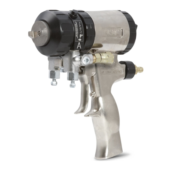
Fusion
Plural component, impingement mix air purge spray gun for dispensing non-flammable
foam and polyurea. For professional use only.
Not approved for use in European explosive atmosphere locations.
3500 psi (24.5 MPa, 245 bar) Maximum Fluid Working
Pressure
80-130 psi (0.56-0.9 MPa, 5.6-9.0 bar) Air Inlet Pressure
Range
200°F (94°C) Maximum Fluid Temperature
See page 4 for model information.
Important Safety Instructions
Read all warnings and instructions in this
manual and in all related manuals before
using the equipment. Save these
instructions.
Important Medical Information
Read the medical alert card provided with
the gun. It contains injection injury
treatment information for a doctor. Keep it
with you when operating the equipment.
®
AP Spray Gun
309550ZAP
EN
TI2408-1A
Advertisement
Chapters
Table of Contents

Related Manuals for Graco Fusion AP


Summary of Contents for Graco Fusion AP
- Page 1 Instructions ® Fusion AP Spray Gun 309550ZAP Plural component, impingement mix air purge spray gun for dispensing non-flammable foam and polyurea. For professional use only. Not approved for use in European explosive atmosphere locations. 3500 psi (24.5 MPa, 245 bar) Maximum Fluid Working Pressure 80-130 psi (0.56-0.9 MPa, 5.6-9.0 bar) Air Inlet Pressure Range...
-
Page 2: Table Of Contents
Inspect the Piston Safety Lock....26 Graco Standard Warranty ....46 Inspect the Check Valves . -
Page 3: Related Manuals
Related Manuals Related Manuals Manual in Description English 309963 Fusion Solvent Flush Kit 309818 Circulation Manifold Kit 3A5616 Fusion Adjustable Flow Cap Kit 311071 Stud Wall Foam Kit and TP100 Kit 3A7314 Fusion PC Spray Gun Instruction Manual 3A7318 Fusion PC Conversion Kit 309550ZAP... -
Page 4: Models
Models Models Round Pattern Guns Mix Chamber Gun Part, Impingement Port Pattern at 24 in (61 Part Equivalent Seal Series Size cm) from target Number Size Material in. (mm) in. (mm) 246099, A AR2020 0.020 (0.50) -000 5 (127) 246100, A AR2929 0.029 (0.70) 8 (203) -
Page 5: Flat Pattern Guns
Models Flat Pattern Guns Mix Chamber Flat Tip Gun Part, Impingement Part Equivalent Part Pattern Size Orifice Size Series Port Size Number Size Number in. (mm) in. (mm) in. (mm) 247101, A AF2020 0.020 (0.50) -000 FT0424 8-10 (203-254) 0.024 (0.61) 247102, A AF2020 0.020 (0.50) -
Page 6: Flat Pattern Stud Wall Gun
Models Flat Pattern Mix Chambers by Pressure and Flow Rate (11.4) 2.25 (8.55) (5.7) 0.75 (2.85) 1000 1500 2000 2500 3000 3500 (3.5, 35) (6.9, 69) (10.3, 103) (13.8, 138) (17.4, 172.4) (20.7, 207) (24.1, 241) PRESSURE in psi (MPa, bar) Flat Pattern Stud Wall Gun Refer to the Stud Wall Foam Kit and TP100 manual for more information. -
Page 7: Four-Hose Gun
Models Four-Hose Gun Wide Round Pattern Gun with Four-Hose Recirculating Gun Manifold Mix Chamber Pattern Diameter at 24 Approximate Flow Gun Part Impingement in. (610 mm) to Target Rate at 1000 psi Part Equivalent Number Port Size in. (mm) (7.0 MPa, 70 bar) Number Size in. -
Page 8: Warnings
Warnings Warnings The following warnings are for the setup, use, grounding, maintenance, and repair of this equipment. The exclamation point symbol alerts you to a general warning and the hazard symbols refer to procedure-specific risks. When these symbols appear in the body of this manual or on warning labels, refer back to these Warnings. Product-specific hazard symbols and warnings not covered in this section may appear throughout the body of this manual where applicable. - Page 9 Warnings WARNING BURN HAZARD Equipment surfaces and fluid that is heated can become very hot during operation. To avoid severe burns: • Do not touch hot fluid or equipment. FIRE AND EXPLOSION HAZARD Flammable fumes, such as solvent and paint fumes, in work area can ignite or explode. Paint or solvent flowing through the equipment can cause static sparking.
- Page 10 Warnings WARNING EQUIPMENT MISUSE HAZARD Misuse can cause death or serious injury. • Do not operate the unit when fatigued or under the influence of drugs or alcohol. • Do not exceed the maximum working pressure or temperature rating of the lowest rated system component.
-
Page 11: Important Isocyanate (Iso) Information
Important Isocyanate (ISO) Information Important Isocyanate (ISO) Information Isocyanates (ISO) are catalysts used in two component materials. Isocyanate Conditions Spraying or dispensing fluids that contain isocyanates creates potentially harmful mists, vapors, and atomized particulates. • Read and understand the fluid manufacturer’s warnings and Safety Data Sheets (SDSs) to know specific hazards and precautions related to isocyanates. -
Page 12: Material Self-Ignition
Important Isocyanate (ISO) Information Material Self-Ignition NOTE: The amount of film formation and rate of crystallization varies depending on the blend of ISO, the humidity, and the temperature. Foam Resins with 245 fa Blowing Agents Some materials may become self-igniting if applied too thick. -
Page 13: Overview
Overview Overview Theory of Operation Gun Detriggered (Air Purging) Mix chamber (19) moves forward, shutting off fluid flow. Impingement ports (IP) open to air chamber (AC), Gun Triggered (Fluid Spraying) allowing purge air to flow through mix chamber nozzle Mix chamber (19) moves back, shutting off purge air (N). -
Page 14: Component Identification
Component Identification Component Identification TI2408A . 1: Component Identification Gun Fluid Manifold A Side Fluid Valve (ISO) Mix Chamber Nozzle B Side Fluid Valve (RESIN) Optional Fluid Inlets (A Side Shown) Air Cap Lock Ring Air Line Quick Coupler Fluid Inlet Swivels (A Side Shown) Muffler Trigger Fluid Housing... -
Page 15: Installation
Installation Installation Grounding 4. Connect gun air whip hose (V) and air valve (W*) to main air hose. Attach fluid manifold (M) to gun. The equipment must be grounded to reduce the risk of static sparking. Static sparking can cause fumes to ignite or explode. - Page 16 Installation 8. Open cleanoff air valve (K) 1/4-1/2 turn and trigger 13. Test spray onto cardboard. Adjust pressure and gun to check that cleanoff air is flowing. Adjust as temperature to get desired results. desired.This step does not apply with spatter pattern spray gun 248408.
-
Page 17: Optional Configurations
Installation Optional Configurations Change Hose Position The fluid inlet swivels and air quick disconnect fitting point to the rear of the gun. If desired, these positions Change Fluid Manifold Position can be changed so hoses travel downward. The fluid manifold is mounted to bottom of gun, with A NOTICE side on left, viewed from operator’s position at back of gun. -
Page 18: Torque To 125-135 In-Lb (14-15 N•M)
Installation Reposition or Replace Flat Spray Tips 5. Apply thread sealant to plugs (12c), elbows (50*), and male threads of fluid inlet swivels (S). Install 1. Follow the Pressure Relief Procedure, page 19. elbows (50*) in optional fluid inlets (P), facing down. Install swivels (S) in elbows. -
Page 19: Operation
Operation Operation Pressure Relief Procedure 4. Trigger the gun onto cardboard or into a waste container to relieve pressure. Follow the Pressure Relief Procedure whenever you see this symbol. TI4722a This equipment stays pressurized until pressure is 5. Engage the piston safety lock (L). See Piston manually relieved. -
Page 20: Piston Safety Lock
Operation Piston Safety Lock Loss of Air Pressure In event of loss of air pressure, gun will continue to spray. To shut off gun, do one of the following: • Engage the piston safety lock. See Piston Safety High-pressure fluid from dispensing devices can Lock. -
Page 21: Daily Shutdown
Operation Daily Shutdown 1. Follow the Pressure Relief Procedure, page 19. 2. Leave the air turned on and gun detriggered. 3. Remove the grease fitting cap. Using the grease gun (Y), dispense grease into fitting (G) until grease mist sprays from mix chamber nozzle (N). Grease your gun daily to prevent two component curing and keep fluid passages clean. -
Page 22: Maintenance
Maintenance Maintenance Preventative Maintenance Recommended Maintenance Procedure Schedule Daily Flush Gun, page 20. Clean Mix Chamber Nozzle, page 23. Clean Air Cap, page 23 Weekly Inspect the Mix Chamber and Side Seal Cartridges, page 24. Check o-rings. Inspect the Check Valves, page 26. Check o-rings and filters. Inspect the Piston Safety Lock, page 26. -
Page 23: Clean Mix Chamber Nozzle
Maintenance Clean Mix Chamber Nozzle Clean Air Cap 1. Follow the Pressure Relief Procedure, page 19. Soak air cap in compatible solvent. Clean holes with #58 (0.042) drill bit. 2. Engage the piston safety lock (L). See Piston Safety Lock, page 20. Clean Impingement Ports 1. -
Page 24: Lubrication
Maintenance Inspect the Mix Chamber and Table 2: Impingement Port Drill Bit Sizes Side Seal Cartridges Counterbore Impingement Port (IP) Mix Chamber Drill Bit Size (CB) Drill Bit Size Part Number in. (mm) See Models, page 4, for available mix chamber sizes. in. - Page 25 Maintenance 7. Pull out side seal cartridges (18). 11. Lubricate and reinstall side seal cartridges (18). NOTICE To prevent cross-contamination in the gun, do not interchange A component (isocyanate) and B component (resin) parts. Cross-contamination can result in cured material in the gun. Cured material may damage the sealing surfaces, block fluid passages, and prevent gun function.
-
Page 26: Inspect The Piston Safety Lock
Maintenance Inspect the Piston Safety Lock Inspect the Check Valves 1. Follow the Pressure Relief Procedure, page 19. 1. Follow the Pressure Relief Procedure, page 19. 2. Disconnect air line quick coupler (D) and remove 2. Follow the Flush Gun procedure, page 20, to fluid manifold (M). -
Page 27: Clean Fluid Manifold
Maintenance Clean Passages 6. Slide filter (26d) off. Clean and inspect parts. Thoroughly inspect o-rings (26f, 26g). If necessary, remove screw (26b) and disassemble entire check If necessary, clean out passages in fluid housing and valve. handle with drill bits. Refer to T 3 and to F . -
Page 28: Inspect The Piston
Maintenance Inspect the Piston 8. Install cylinder cap (5). 1. Follow the Pressure Relief Procedure, page 19. 2. Disconnect air line (D) and remove fluid manifold (M). TI2430A 9. Follow the Attach Front End procedure, page 29. 10. Attach fluid manifold. Connect air. Return gun to service. -
Page 29: Remove Front End
Maintenance Remove Front End 2. Push on air cap (C) until it is flush with front of gun. This ensures that mix chamber is all the way back. 1. Follow the Pressure Relief Procedure, page 19. 2. Follow the Flush Gun procedure, page 20. NOTICE TI2422A If lock ring (R) is stuck due to material buildup, do not... -
Page 30: Troubleshooting
Troubleshooting Troubleshooting 1. Follow the Pressure Relief Procedure, page 19, before checking or repairing the gun. 2. Check all possible problems and causes before disassembling the gun. NOTICE To prevent cross-contamination in the gun, do not interchange A component (isocyanate) and B component (resin) parts. - Page 31 Troubleshooting Problem Cause Solution Loss of flat pattern The spray tip is plugged. Clean in compatible solvent. See Reposition or Replace Flat Spray Tips, page 18. The tip is worn. Replace the flat spray tip. See Reposition or Replace Flat Spray Tips, page 18.
- Page 32 Troubleshooting Problem Cause Solution Rapid buildup of material on air cap. The air cap holes are plugged. Clean the air cap holes. See Clean Air Cap, page 23. Too little cleanoff air. Increase cleanoff air. See Setup, page 15. The fluid housing o-ring (23) is Replace the fluid housing o-ring.
-
Page 33: Parts
Parts Parts NOTE: The round pattern gun is shown below. Refer to Detail Views, page 35, for parts specific to other models. Seal Cartridge (18) Detail 18e‡ 18b‡ 18c‡ 18d‡ 18a‡ TI3926A Check Valve (26) Detail ‡37 26b‡... - Page 34 SEAL KIT, see Side Seal Kits, page www.graco.com 248279 GREASE, tube, 4 oz, not shown; 248130 O-RING, cartridge body; package of 6 sheet available at www.graco.com 248128 O-RING, side seal, package of 6 - - - - CHAMBER, mix; see Mix Chamber NOTE: See Detail Views, page 35, for additional parts.
-
Page 35: Detail Views
Parts Detail Views Flat Pattern Detail Flat Pattern Stud Wall Foam Detail Splatter Tip Detail 10 60 59 61 58 TI2557A TI4555B 62 Flush Manifold Supplied Tools 64 63 TI4660C-1 33 (Ref) 35 (Ref) 4-Hose Fluid Manifold Detail TI3870A 12d (Ref) TI2647A Torque to 125-135 in-lb (14-15 N•m). -
Page 36: Mix Chamber Kits
Parts Mix Chamber Kits Mix Chamber Part Reference Guide Example part number AR4242: AR=Air purge round pattern A orifice size B orifice size (0.042 in.) (0.042 in.) AF=Air purge flat pattern Round Pattern Stainless Chromex Nozzle Nozzle Drill Impingement Impingement Counterbore Counterbore Steel Mix... -
Page 37: Flat Tip Kits
Parts Flat Pattern Mix Chamber Nozzle Orifice Nozzle Drill Impingement Impingement Port Counterbore Counterbore Drill Kit (includes Size Bit Size, Port Size Drill Bit Size, Size Bit Size, drill bits and in. (mm) in. (mm) in. (mm) o-ring) AF2020 0.094 3/32 (2.35) 0.020 #76 (0.50) -
Page 38: Gun Repair Kits
Parts Gun Repair Kits Read the chart left to right and top to bottom to find the quantity of each part in the kits. Includes 246347 246351 246355 25M221 Bulk O-ring Side Seal Cartridge 246348 Check Valve Complete High Temperature Ref. -
Page 39: Drill Bit Kits
Parts Drill Bit Kits For cleaning gun ports and orifices. Illustrations are for 1 in. diameter comparison. Actual length may vary. (25.4 mm) 1 in. NOTE: Not all sizes are used with your gun. (25.4 mm) Drill Bit Size Kit Part Qty. nominal Illustration 249115... -
Page 40: Reamer Kits
Parts Drill Bit Size Kit Part Qty. nominal Illustration 246808 0.040 1.02 248640 0.039 0.99 248618 0.037 0.94 248891 0.033 0.84 246807 0.032 0.81 246630 0.029 0.74 248892 0.028 0.71 246815 0.024 0.61 276984 0.023 0.57 246631 0.020 0.51 246816 0.018 0.46 246817 0.013 0.33... -
Page 41: Accessories
Accessories Accessories Fusion PC Conversion Kits For converting the Fusion AP spray gun to a Fusion PC spray gun for use with ProConnect™ fluid cartridges. See Related Manuals, page 3. Round Pattern Mix Chamber Pattern at 24 Conversion Part Impingement Port Size Equivalent in. -
Page 42: Side Seal Kits
Accessories Side Seal Kits Side Seal Cartridge Kits Kits includes a packing o-ring for each seal. Material Kit Part Description Qty. Stainless 246349 CARTRIDGE KIT, A side Material Description Qty. Steel 246348 CARTRIDGE KIT, B side Stainless Steel 246348 SEAL KIT Polycarballoy 277297 CARTRIDGE KIT, A side 277299 SEAL KIT... -
Page 43: Pour Nozzle Kit
Adjustable Flow Cap Kit 246945 To connect Graco Fusion gun to non-Graco heated 25D632 hose. To allow variable flow to the Fusion AP gun. Refer to the Fusion Adjustable Flow Cap Kit manual. See Related Spatter Conversion Kit Manuals, page 3. 248414 To convert Fusion air purge gun to spray round pattern only, large droplet, low overspray applications. -
Page 44: Solvent Flush Canister Kit
Accessories Solvent Flush Canister Kit Tip Cleanout Tool 248139, 1 qt (0.95 l) Solvent Cup 15D234 Complete with 15B817 Flushing Manifold to flush gun Designed to fit CeramTip internal dome and flat tip slits. with solvent. Portable for remote flushing. Refer to the Solvent Flush Kit manual. -
Page 45: Technical Specifications
Technical Specifications Technical Specifications Fusion Air Purge Spray Gun Metric Maximum Fluid Working Pressure 3500 psi 24.5 MPa, 245 bar Minimum Air Inlet Pressure 80 psi 0.56 MPa, 5.6 bar Maximum Air Inlet Pressure 130 psi 0.9 MPa, 9 bar Air Flow Range See chart below Typical Flow Rate of Round Pattern Guns... -
Page 46: Graco Standard Warranty
With the exception of any special, extended, or limited warranty published by Graco, Graco will, for a period of twelve months from the date of sale, repair or replace any part of the equipment determined by Graco to be defective.
Need help?
Do you have a question about the Fusion AP and is the answer not in the manual?
Questions and answers