Table of Contents
Advertisement
Quick Links
Advertisement
Table of Contents

Related Manuals for avertX AVX-HD119IR


Summary of Contents for avertX AVX-HD119IR
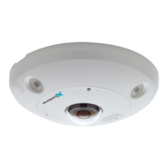
- Page 1 HD119IR 9MP OUTDOOR FISHEYE CAMERA WITH BUSINESS ANALYTICS User Manual...
- Page 2 The information in this publication is provided “as is” without warranty of any kind. The entire risk arising out of the use of this information remains with recipient. In no event shall AVERTX be liable for any direct, consequential, incidental, special, punitive, or other damages whatsoever (including without limitation,...
- Page 3 Before using, make sure power supply and others are properly connected. • While operating, if any abnormal condition or malfunction is observed, stop using the camera immediately and then contact AvertX Customer Support. Handling Do not disassemble or tamper with parts inside the camera.
- Page 4 REGULATION This device complies with Part 15 of the FCC Rules. Operation is subject to the following two conditions: (1) this device may not cause harmful interference, and (2) this device must accept any interference received, including interference that may cause undesired operation. This symbol on the product or on its packaging indicates that this product shall not be treated as household waste in accordance with Directive 2002/96/EC.
-
Page 5: Table Of Contents
TABLE OF CONTENTS INTRODUCTION ............................... 7 Overview ..............................7 Camera Default Settings ......................7 Product Features ........................7 GETTING STARTED ..............................8 Box Contents ............................8 Camera Overview ............................. 9 Camera Diagram ........................9 Dimensions ..........................10 Installing the Camera ..........................11 Resetting the Camera ...................... - Page 6 User Management ........................29 Online Users ........................29 Network ..............................30 Basic Settings ........................... 30 Basic Settings > TCP/IP ....................30 Basic Settings > DDNS ..................... 31 Basic Settings > Port ......................31 Advanced Settings ........................32 Advanced Settings > HTTPS ..................... 32 Stream Settings ............................
-
Page 7: Introduction
IP Address 192.168.51.2 Username admin This AvertX camera model does not have a default password The admin user password can be set using the following methods: 1. ProConnect recorders running software version 2.1 or newer will automatically set a new unique password by: ... -
Page 8: Getting Started
BOX CONTENTS Before proceeding, please check that the box contains the items listed here. If any item is missing or has defects, do not install or operate the product and contact your dealer for assistance. AVX-HD119IR Camera Mounting Screws Plastic Anchors... -
Page 9: Camera Overview
CAMERA OVERVIEW Before installing or connecting the camera, please refer to this section and complete preparations for camera setup and all switch settings. Camera Diagram Use the reset button to restore the factory default settings. To reset your camera: Disconnect the cat5e cable from the camera for 30 seconds. Reset Button Hold the reset button down while reconnecting cat5e and continue holding the reset button for 30 seconds after... -
Page 10: Dimensions
Dimensions 37601AA... -
Page 11: Installing The Camera
INSTALLING THE CAMERA Weather Resistant Cable Connector This camera features an IP66-rated weather resistant connector. For unprotected outdoor connections, screw the connector on the included Ethernet camera cable onto the camera dongle. If your installation location does not require a water-resistant connection, loosen and slide the connector back on the cable until it’s out of the way. - Page 12 Pay careful attention to lens orientation when mounting. Improper lens orientation will result in a skewed image. Proper lens orientation is with the AvertX logo at the bottom. “TOP” is also marked with an arrow on the mounting template. When mounting on a wall, orient the AvertX logo on top.
- Page 13 Direct to Ceiling or Wall Installation 1. Apply drill template to the desired installation location. 2. Using a 5mm bit, drill three holes for the plastic anchors. 3. Using a 1” bit, drill the cable hole. Insert plastic anchors & thread the screws halfway into the anchors. 5.
- Page 14 Inclined or Junction Box Mount - Ceiling or Wall Installation PRO TIP: This mount is compatible with single and dual gang electrical boxes. If connecting this mount to a single or dual gang electrical box, skip to number 6. 1. Apply drill template to the desired installation location. 2.
-
Page 15: Resetting The Camera
PRO TIP: Use the AvertX Connect mobile app to view the camera while adjusting view. NOTICE: AvertX recommends sealing the opening at the wall and at the base of the camera with silicone caulking. For best IR Night Vision performance: Be aware of surfaces that can cause IR light to reflect into the camera. -
Page 16: Connecting
Once the camera is connected to the recorder, test all functions to ensure proper operation. If the camera will not connect or is not functioning correctly, do not install, and contact AvertX Support. NETWORK CAMERA MANAGER Network Camera Manager (NCM) is a software tool that allows you to quickly and easily connect and configure your AvertX IP cameras. -
Page 17: Connecting To The Camera
1. AvertX ProConnect recorders will check the camera for a password once connected. If AvertX software does not detect a password, it will set the camera password to a secure text string of 8 to 16 characters (Including upper-case letters, lower-case letters, digits and special characters (!"#$%&'()*+,-./:;<=>?@[\]^_`{|}~ space)). -
Page 18: Logging Into The Web Interface
LOGGING INTO THE WEB INTERFACE The default static IP address of the camera is 192.168.51.2, and the default subnet mask is 255.255.255.0. DHCP is turned on by default. If a DHCP server is used in the network, the IP address of your camera will be assigned dynamically. -
Page 19: Live View
LIVE VIEW Description Browse to Live View page to view live video Browse to Playback page to view video recorded to onboard storage Browse to the Advanced Page Current user account Exit the device interface Change Aspect Ratio in Live View Select which stream displays in Live View Start/Stop Live View Capture live view image and save to selected location... -
Page 20: Reports
REPORTS The Reports page is used to search, view, and export the Heatmapping and People Counting data stored in the local storage or network storage. People Counting Statistics People Counting Statistics is a graphical representation of persons entering and/or leaving a defined area represented by a list, bar chart, or line chart. -
Page 21: Bar Chart
Bar Chart Based on which Report Type you choose, Bar Chart view will display the data in a list by hour of the day, day of the week, day of the month, or month of the year. Line Chart Based on which Report Type you choose, Line Chart view will display the data in a list by hour of the day, day of the week, day of the month, or month of the year. -
Page 22: Heat Map Statistics
Heat Map Statistics Heat map is a graphical representation of data represented by colors which can be used to analyze the visit times and dwell time of customers in a defined area. To get more intuitional results, you can display the data in different charts. Select the Report Type by clicking the drop-down menu. -
Page 23: Advanced
ADVANCED SYSTEM System Settings Basic Information Basic Information displays details about the camera. Device Name and Device No. are customizable. 37601AA... -
Page 24: Time Settings
Time Settings Configure the time synchronization and DST settings. Select the Time Zone of your location from the drop-down menu. To configure the NTP settings: 1. Click to enable the NTP function. 2. Configure the following settings: Server Address: IP address of NTP server. NTP Port: Port of NTP server. -
Page 25: Dst (Daylight Savings Time)
DST (Daylight Savings Time) Configure daylight savings time, if needed. To configure DST: 1. Select the Start Time and the End Time. 2. Select the DST Bias. 3. Click Save to activate the settings. About Click View Licenses to check information about the open source software that applies to the IP camera. -
Page 26: Maintenance
Maintenance Upgrade & Maintenance Process the operations, including reboot, partly restore, restore to default, export/import the configuration files, and upgrade the device. Reboot: Restart the device. • • Restore: Reset all the parameters, except the IP parameters and user information, to the default settings. -
Page 27: Log
Export the camera log files. To export log files: 1. Set the log search conditions to specify the search, including Major Type, Minor Type, Start Time and End Time. 2. Click Search to search log files. The matched log files will be displayed on the log list interface. -
Page 28: Security
Security Configure the parameters, including Authentication, IP Address Filter. Authentication 1. Set up authentication method for RTSP Authentication and WEB Authentication. CAUTION: Digest is the recommended authentication method for better data security. Be aware of the risk if you adopt basic as the authentication method. 2. -
Page 29: User Management
User Management As Administrator: The admin user can Add, Modify or Delete user accounts, and grant them different permissions. We highly recommend you manage the user accounts and permissions properly. Note: Admin password is required for adding and modifying a user account. Adding a User The admin user has all permissions by default and can create, modify or delete other accounts. -
Page 30: Network
NETWORK Basic Settings Basic Settings > TCP/IP Configure the basic network settings, including the NIC Type, IP Address, Subnet Mask, Gateway, MTU settings and Multicast Address. (Optional): 1. Configure the DNS server. Input the preferred DNS server, and alternate DNS server. 2. -
Page 31: Basic Settings > Ddns
Basic Settings > DDNS Before you start: Registration on the DDNS server is required before configuring the DDNS settings of the camera. 1. Check the Enable DDNS checkbox to enable this feature. 2. Select DDNS Type. Two DDNS types are selectable: DynDNS and NO-IP. DynDNS: 1. -
Page 32: Advanced Settings
Advanced Settings Advanced Settings > HTTPS HTTPS provides authentication of the web site and its associated web server, which protects against Man-in-the-middle attacks. Notes: • HTTPS is enabled by default. • If HTTPS is enabled, the camera creates an unsigned certificate automatically. 1. -
Page 33: Stream Settings
Video Encoding: The camera supports multiple video encodings types, such as H.264, • H.264+, H.265, and H.265+. IMPORTANT: AvertX ProConnect recorders do not currently support H.265/H.265+ video encoding. Note: The camera will require a reboot to turn H.264+/H.265+ on or off. - Page 34 Audio Configure the following audio settings: Audio Encoding G.711ulaw Is the only available option Audio Input MicIn and LineIn are selectable for the connected microphone and pickup respectively. MicIn is selected by default. Input Volume Set the Input Volume to the desired level from 0-100. Environmental Noise Filter Set it as ON or OFF.
-
Page 35: Image
IMAGE Display Settings Configure the image adjustment, exposure settings, day/night switch, backlight settings, white balance, image enhancement, video adjustment, and other parameters in display settings, OSD settings, and privacy mask. Image Adjustment Brightness describes brightness of the image, which ranges from 1 to 100. •... -
Page 36: Exposure Settings
Saturation Set the intensity of color in the image. Low saturation High saturation Contrast Set the degree of difference between the blackest pixel and the whitest pixel. Low contrast High contrast Sharpness Contrast of boundaries of objects in an image. Low sharpness High sharpness Digital Noise... -
Page 37: Backlight Settings
Night: The camera provides high-quality black and white images using the existing light. Auto: The camera outputs the optimum images according to the light condition. In this mode, the camera can switch between night mode and day mode automatically. Sensitivity ranges from 0 to 7, the higher the value is, the easier the mode switches. •... -
Page 38: White Balance
White Balance White balance is the process of offsetting unnatural color cast in images under different color temperatures so as to output images that best suit human eyes. Image Enhancement Digital Noise Reduction: DNR reduces the noise in the video stream. OFF, Normal and •... -
Page 39: Osd Settings
OSD Settings Customize the camera name, time/date format, display mode, and OSD size displayed in live view. To configure OSD settings: 1. Check the applicable checkbox to display the camera name, date or week. 2. Edit the camera name in the text field of Camera Name. 3. -
Page 40: Privacy Mask
Privacy Mask Privacy mask enables you to cover certain areas on the live video to prevent certain spots in the surveillance area from being viewed and recorded. rivacy mask areas are used to protect privacy. For example, a privacy mask can cover the keypad of an ATM machine or the entry to fitting rooms. To configure privacy masks: 1. -
Page 41: Event
EVENT Motion Detection Motion detection detects moving objects in the defined areas. In order to detect the moving objects accurately and reduce the false alarm rate. To configure Normal motion detection: 1. Check Enable Motion Detection. 2. Click Draw Area. Click and drag the mouse on the live video to draw a motion detection area. -
Page 42: Set The Arming Schedule For Motion Detection
Set the Arming Schedule for Motion Detection To configure the motion detection schedule: 1. Click on the time bar and drag the mouse to select the time period. Note: Click on the selected time period, you can adjust the time period to the desired time by either moving the time bar or input the exact time period. -
Page 43: Set The Linkage Method For Motion Detection
Set the Linkage Method for Motion Detection Use the checkboxes to enable the available actions. ACTIONS (Arming Schedule must be configured to enable): Record Video to Memory Card – Video will be recorded when motion is detected. Upload Snapshots to Memory Card – Capture the image when motion is detected and save the picture to the onboard microSD card. -
Page 44: Storage
STORAGE Schedule Settings Schedule Settings > Record Schedule This camera includes an integrated microSD™ card slot that can be used to record video. The card slot is compatible with a microSD™ card up to 512GB. This section is used to define when video should be recorded to the microSD card. -
Page 45: Schedule Settings > Capture Schedule
Note: In addition to configuring the recording schedule, the schedule and actions must also be configured in the Motion Detection settings. Event: video will be recorded when an event occurs. Note: In addition to configuring the recording schedule, the schedule and actions must also be configured in the Analytics settings. -
Page 46: Schedule Settings > Capture Parameters
Schedule Settings > Capture Parameters 1. Check Enable Timing Snapshot. 2. Select the Quality and Capture Interval. Quality: Low, Medium, High • Interval: length of time between images • Available options are Millisecond, s (second), minute(s), hour, day(s) 3. Check Enable Event-Triggered Snapshot. 4. -
Page 47: Storage Management
Storage Management View the capacity, free space, status, type, formatting type, and property of the disk. Note: The camera must be powered off when installing or removing the microSD card. If the status of the disk is Uninitialized, check the corresponding checkbox to select the disk and click Format to start initializing the disk. -
Page 48: People Counting
People Counting People Counting provides the necessary data to assist in managing labor allocation at peak service times. IMPORTANT: Set the date and time on the camera to ensure accuracy in your People Counting reports. 1. Enable People Counting People Counting is enabled when the checkbox is checked and disabled when unchecked. 2. - Page 49 Manually captures a snapshot from live video and downloads the image to your computers downloads folder. 8. Start/Stop Recording Manually start and stop recording live video. The video will be saved to your local PC when recording is stopped. 9. On-Screen Display Click inside the box and drag to reposition the OSD.
-
Page 50: Data Uploading
Data Uploading Display Configurations Real-Time Upload Data ON: Updates count data based on increment of time selected for Data Refresh Cycle. • • OFF: Turns off real time upload Data Refresh Cycle Select how frequently data will be refreshed; 1, 5, 10, 15, 20, 30, and 60 minutes(s) are the •... -
Page 51: Heat Map Configuration
Heat Map Configuration Heatmapping provides the necessary data to assist in managing labor allocation at peak service times as well as maximizing upsell opportunities by identifying high traffic areas. IMPORTANT: Set the date and time on the camera to ensure accuracy in your Heat Map reports. 1. - Page 52 5. Select All Select the entire image as the detection area. 6. Clear Clear all detection areas and min/max boxes. 7. Start/Stop Recording Manually start and stop recording live video. The video will be saved to your local PC when recording is stopped.
- Page 53 All rights reserved. No part of this publication may be reproduced by any means without written permission from AvertX. The information in this publication is believed to be accurate in all respects. However, AvertX cannot assume responsibility for any consequences resulting from the use thereof. The information contained herein is subject to change without notice.
Need help?
Do you have a question about the AVX-HD119IR and is the answer not in the manual?
Questions and answers