Table of Contents
Advertisement
Quick Links
Advertisement
Table of Contents

Subscribe to Our Youtube Channel
Related Manuals for Overland Storage LoaderXpress


Summary of Contents for Overland Storage LoaderXpress
- Page 1 Part No. 104249-102 04/2004...
- Page 2 All information contained in or disclosed by this document is considered proprietary by Overland Storage. By accepting this material the recipient agrees that this material and the information contained therein are held in confidence and in trust and will not be used, reproduced in whole or in part, nor its contents revealed to others, except to meet the pur- pose for which it was delivered.
- Page 4 Preface Purpose of This Manual This manual provides step-by-step installation instructions, and information required for ongoing use and maintenance of the LoaderXpress tape drive system. This manual is written for the installer and user of this equipment. Organization The following information is contained in this manual.
- Page 6 xiii...
-
Page 7: Table Of Contents
Chapter 1 - Introduction Introduction........................ 1-1 Figure 1–1 LoaderXpress ..................1-1 Benefits ........................1-1 Features ........................1-2 Table 1–1 LoaderXpress Features ..............1-2 Front Panel ......................... 1-2 Figure 1–2 Front Panel..................1-2 Table 1–2 Front Panel Controls and Indicators ..........1-3 Control Panel ......................1-3 Figure 1–3 Control Panel ..................1-3... - Page 8 Figure 2–10 Rack Slides Separated ..............2-8 Figure 2–11 Attaching the Inner slide..............2-9 Installing the LoaderXpress in the Rack ............... 2-9 Figure 2–12 Rack Slide Callouts .................2-9 Figure 2–13 Mounting Screw Locaations............2-10 Figure 2–14 Rack Slide Mounting Holes ............2-10 Figure 2–15 Install Clip Nuts ................
- Page 9 Figure 3–5 Default Screens .................3-5 Fault Screen ......................3-6 Figure 3–6 Fault Screen..................3-6 The DLT/SDLT LoaderXpress Menu Structure ............3-7 Figure 3–7 DLT/SDLT LoaderXpress Menu Structure .........3-7 The DLT/SDLT Loader Menu Structure ..............3-8 Figure 3–8 DLT/SDLT Loader Menu Structure ............3-8 The LTO Loader Menu Structure ................
- Page 10 Figure 3-8 Security Menu .................. 3-17 Figure 3-9 Code Select Submenu ..............3-17 Figure 3-10 Code Accept Submenu............... 3-18 Unlocking the Control Panel................3-18 Figure 3-11 Panel Locked Screen ..............3-18 Figure 3-12 Code Entry Submenu..............3-19 Displaying Firmware Revision ................3-19 Inserting &...
- Page 11 Chapter 5 - Troubleshooting Diagnosing Problems ....................5-1 Platform Problems ....................5-1 General Drive Errors ....................5-1 Error Recovery Flow Chart..................5-1 Error Recovery Procedures..................5-2 Fault Symptom Codes (FSC) ..................5-3 Table 5–1 Fault Symptom Codes...............5-3 Using the Demo Submenu ..................5-18 Pausing Demo 1 ....................
- Page 13 List of Figures Chapter 1 - Introduction Figure 1–1 LoaderXpress ....................1-1 Figure 1–2 Front Panel ....................1-2 Figure 1–3 Control Panel....................1-3 Figure 1–4 Rear Components ...................1-4 Figure 1–5 Tape Cartridge Magazine ..............1-5 Chapter 2 - Installation Figure 2–1 Unpacking the Loader ................2-2 Figure 2–2 Tabletop Clearance Allowance ............2-3...
- Page 14 Figure 3–5 Default Screens..................3-5 Figure 3–6 Fault Screen ..................... 3-6 Figure 3–7 DLT/SDLT LoaderXpress Menu Structure ..........3-7 Figure 3–8 DLT/SDLT LoaderXpress Menu Structure ..........3-8 Figure 3–9 LTO LoaderXpress Menu Structure............3-9 Figure 3–10 LTO LoaderXpress Menu Structure............. 3-10 Figure 3-1 Main Menu-.....................
- Page 15 List of Tables Chapter 1 - Introduction Table 1–1 LoaderXpress Features .................. 1-2 Table 1–2 Front Panel Controls and Indicators.............. 1-3 Table 1–3 Control Panel Controls and Indicators............1-3 Table 1–4 Rear Components .................... 1-4 Chapter 2 - Installation Table 2–1 Power Cord Rating ..................2-20 Table 2–2 LoaderXpress Configuration Options............
-
Page 17: Chapter 1 - Introduction
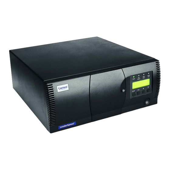
Chapter 1: Introduction Introduction This chapter introduces you to the LoaderXpress. It includes an overview of the followings sections: • Benefits • Features • Front Panel • Control Panel • Rear Components • Tape Cartridge Magazines Figure 1–1 LoaderXpress Benefits TheLoaderXpress is a compact, easy-to-use tape loader, which includes many features ideally suited to applications requiring automated backup. -
Page 18: Features
• Embedded diagnostics for verification and memory testing at power-up and for user and customer engineer troubleshooting Features The LoaderXpress features the following: Table 1–1 LoaderXpress Features Feature/Component Description Number of Drives... -
Page 19: Table 1-2 Front Panel Controls And Indicators
ONTROL ANEL Table 1–2 Front Panel Controls and Indicators Component Description Magazine Door Used to gain access to the magazine. Includes electronically controlled locks. Access is gained via the Control Panel menu. Power Switch Pushbutton switch used to apply power to the unit. -
Page 20: Rear Components
OMPONENTS Rear Components SCSI TERMINATOR This dev ice co mp lie s with Part 15 o f FC C ru les Op era tion is This device complies with Part 15 of FCC rules Operation is xxxx xxxxxxxx xxxxxxxx xxxxxxx xxxxxxxx xxxxxxxx xxxxxxxx xxxxxxx xxxxxxxx xx xxxxxxxxxxxxxxxxxxxxxxxxxxxxxxxxxxxxxxxxxxxxxxxxxxxxxxxxxxxxxxxxxxxx xxxx xxxxxxxx xxxxxxxx xxxxxxx xxxxxxxx xxxxxxxx xxxxxxxx xxxxxxx xxxxxxxx xx xxxxxxxxxxxxxxxxxxxxxxxxxxxxxxxxxxxxxxxxxxxxxxxxxxxxxxxxxxxxxxxxxxxx... -
Page 21: Figure 1-5 Tape Cartridge Magazine
Slot 1 DLT/SDLT LXL-0026a Figure 1–5 Tape Cartridge Magazine The LoaderXpress is equipped with a 10-cartridge (DLT/SDLT) or 11-cartridge(LTO) magazine. The magazine is made of rugged molded polymer, which fits into an extruded track, for precise positioning with the robotics. Introduction... -
Page 22: Tape Cartridge Magazines
ARTRIDGE AGAZINES Introduction... -
Page 23: Chapter 2 - Installation
Chapter 2: Installation Introduction This chapter describes the installation of your LoaderXpress. It includes: • Unpacking • Installation Notes • Tabletop Placement & Setup • Rack Mount Installation (If applicable) • Inserting & Removing Cartridges • Interface Descriptions • Host Computer Connection •... -
Page 24: Figure 2-1 Unpacking The Loader
Tabletop Placement & Setup 1) Place the LoaderXpress on a stable horizontal surface with at least a 2-inch clearance behind the chassis to allow for cable installation and sufficient cooling air to flow freely from the cooling fan. See Figure 2–2. -
Page 25: Figure 2-2 Tabletop Clearance Allowance
Figure 2–2 Tabletop Clearance Allowance Rack Mount Installation (If applicable) The LoaderXpress can be mounted in a standard 19-inch EIA/RETMA rack with a depth of 24 to 30 inches. Units that are purchased as rackmount units are shipped with the top cover and rack slides installed. -
Page 26: Figure 2-3 Cooling Fan Clearance
Figure 2–3 Cooling Fan Clearance Removing the Skin and Installing the Top Cover The skin is held in place by four screws at the rear panel of the LoaderXpress. Users that purchase the LoaderXpress as rack mount ready (top cover installed) may skip this section and proceed to “Installing the LoaderXpress in the... -
Page 27: Figure 2-4 Removing Outer Skin
LXL-0004 Figure 2–4 Removing Outer Skin 2) Place the top cover on top of the LoaderXpress with the cover's front edge about one inch behind the front panel. Slide the top cover forward as far as it will go. Install two of the four screws removed when you removed the skin. -
Page 28: Rack Slides
NOTE: The left and right slides are alike, so there is no risk of confusing the parts on reassembly. 1) Refer to Figure 2–6 to identify and orient the parts of the slides. The slide is attached to the LoaderXpress pem enclosure by means of three screws through the inner slide. Front Attached to the chassis... -
Page 29: Figure 2-7 Separating Rack Slides
OUNT NSTALLATION F APPLICABLE LXL-0047a Figure 2–7 Separating Rack Slides LXL-0071 Figure 2–8 Separating Rack Slides • Continue to pull the outer slide towards the rear until the outer slide lock engages the intermediate slide. Press the inner slide lock button to permit the intermediate slide to continue to move toward the rear. -
Page 30: Figure 2-9 Rack Slides Separated
OUNT NSTALLATION F APPLICABLE LXL-0056 Figure 2–9 Rack Slides Separated LXL-0057 Figure 2–10 Rack Slides Separated 3) For Tabletop conversions: Place one of the inner slides against one side of the chassis so that the holes in the inner slide are aligned with the holes in the chassis. -
Page 31: Figure 2-11 Attaching The Inner Slide
Figure 2–11 Attaching the Inner slide 5) Repeat steps 3 and 4 for the other slide on the other side of the chassis. Installing the LoaderXpress in the Rack Refer to the figures for identification of parts and unit/slide mounting holes. -
Page 32: Figure 2-14 Rack Slide Mounting Holes
½ inch space Location of rails and to the center of the mounting hardware next ½ inch space. for the LoaderXpress The Overland LoaderXpress uses 4 U of rack space. Hole spacing = 5/8 inch Nut Clips Hole spacing = ½... -
Page 33: Figure 2-15 Install Clip Nuts
OUNT NSTALLATION F APPLICABLE (Outer slide installed Clip Nut for clarity) Figure 2–15 Install Clip Nuts Rear Front LXL-0060 Figure 2–16 Outer Slide and Mounting Hardware 3) Snugly assemble (do not tighten) an adjustable mounting bracket to each outer slide on the rear of the unit, using two 10-32 screws with washers and a nut plate. -
Page 34: Figure 2-17 Adjustable Mounting Bracket
Rear LXL-0062 Figure 2–18 Adjustable Mounting Bracket 5) Fasten each outer slide behind (for LoaderXpress in racks with a 24” depth) the front rail of the rack using two 10-32 screws with washers and one nut plate as depicted in Figure 2–19. -
Page 35: Figure 2-19 Outer Rail Mounting (Front)
OUNT NSTALLATION F APPLICABLE LXL-0063 Figure 2–19 Outer Rail Mounting (Front) 6) Fasten each of the mounting brackets to the front of the rear rail of the rack using two 10-32 screws and one nut plate. NOTE: When fastening the adjustable bracket, allow room for the slide to pass by the inside of the rack as depicted in Figure 2–20. -
Page 36: Figure 2-21 Rack Slide Extended
9) At front of the rack, lift the module to its installed height. Engage the inner slides mounted on the LoaderXpress with the intermediate slides protruding from the rack, and slide the LoaderXpress toward the rack until the inner slide lock engages the intermediate slide. This leaves the entire LoaderXpress protruding from the rack, locked in position, supported by slides. -
Page 37: Figure 2-23 Test For Binding
Front LXL-0060 Figure 2–24 Front & Rear Slide Hardware 13)If necessary, repeat previous 2 steps until the LoaderXpress chassis does not bind against the slides. 14)Slide the LoaderXpress into the rack, and install and tighten one 10-32 thumb screw through each panel extension (left and right sides) into the clip nuts. -
Page 38: Figure 2-25 Installed Panel Extender
Prevent/Allow Medium Removal command. To release the lock, exit the host software. If host computer failure prevents the host from releasing the lock, cycle power to the LoaderXpress. If you are still unable to open the magazine door, see “Emergency Magazine Removal”. -
Page 39: Figure 2-26 Magazine Door Open
(LTO). After you insert the desired cartridges into the magazine, position the magazine so the cartridges protrude to the left, and the magazine handle is toward you. Insert the magazine into the LoaderXpress with that orientation, see Figure 2–27. -
Page 40: Figure 2-27 Cartridge Media
SCSI Terminator - Used to terminate the last unit in a Daisy Chain. • SCSI-2 - Ultra 2 / Wide LVD uses high-density 68 pin connectors. All SCSI cables used with the LoaderXpress should meet the following requirements: • Shielded or double-shielded, as required to meet EMI specifications •... -
Page 41: Figure 2-28 Interface Connections
OMPUTER ONNECTION SCSI TERMINATOR This dev ice co mp lie s with Part 15 o f FC C ru les Op era tion is This device complies with Part 15 of FCC rules Operation is xxxx xxxxxxxx xxxxxxxx xxxxxxx xxxxxxxx xxxxxxxx xxxxxxxx xxxxxxx xxxxxxxx xx xxxxxxxxxxxxxxxxxxxxxxxxxxxxxxxxxxxxxxxxxxxxxxxxxxxxxxxxxxxxxxxxxxxx xxxx xxxxxxxx xxxxxxxx xxxxxxx xxxxxxxx xxxxxxxx xxxxxxxx xxxxxxx xxxxxxxx xx xxxxxxxxxxxxxxxxxxxxxxxxxxxxxxxxxxxxxxxxxxxxxxxxxxxxxxxxxxxxxxxxxxxx... -
Page 42: Figure 2-29 Single Host Configuration
OWER OURCE ONNECTION 3) If the LoaderXpress is one of several units you are connecting to the host, connect them in a daisy-chain by doing the following: • Connect the cable from the host, to one of the SCSI connectors of the first SCSI device •... -
Page 43: Configuring The Loaderxpress
Table 2–1 Power Cord Rating Europe Harmonized marked <Har> or nationally certi- fied Configuring the LoaderXpress You can change configuration option settings if necessary from the Control Panel. Before changing any settings, refer to your host system documentation or contact your Technical Support representative. -
Page 44: Set Data Format
ONFIGURING THE OADER PRESS Load/Unload Unlock Door Show status Menu Maintenance Menu 2) Press the button to scroll to the Configure Menu option. and press Enter Unlock Door Maintenance Menu Configure Menu Security Menu Set Data Format Set SCSI Set Library Mode Set Element Base 3) Press the button to scroll to the option you want to change. -
Page 45: Set Identification
ONFIGURATION PTIONS ESCRIPTIONS Configuration Options Descriptions You can change the following options on the Configure Submenu: NOTE: Configuration Options defaults are listed below in Table 2–2. Set Data Format This setting allows you to set the data format and enable or disable data compression. This setting applies to the next or the currently, loaded cartridge only. -
Page 46: Set Date
ONFIGURATION PTIONS ESCRIPTIONS Set Date This enables you to set the module’s calendar. Set Time This enables you to set the module’s clock. Set Baud Rate This enables you to set the data transmission rate of the module’s trace port. This function is intended for use by CE’s only. -
Page 47: Set Special Configurations
Special Configurations section of Table 2–2 for a list of options and default values. Set Default The Default option resets all of the preceding configuration options to factory defaults. Table 2–2 LoaderXpress Configuration Options SDLT Option Available Options Default Default... - Page 48 ONFIGURATION PTIONS ESCRIPTIONS Table 2–2 LoaderXpress Configuration Options (Continued) Set Time Hour, Minute Time Time Time Set Baud Rate [Overland CE Use Only] 38,400 115,200 115,200 Set Serial Number Select number and alpha numerics Unit specific Unit spe- Unit spe-...
- Page 49 ONFIGURATION PTIONS ESCRIPTIONS Table 2–2 LoaderXpress Configuration Options (Continued) Post Recv'd Error: Disabled, Disabled Disabled Disabled Enabled Tape Alert Mode: Logging Dis- Logging Dis- Logging Logging abled, No Exceptions, Unit Atten- abled Disabled Disabled tion, Rec. Error (cnd), Rec. Error...
- Page 50 ONFIGURATION PTIONS ESCRIPTIONS 2-28 Installation...
-
Page 51: Chapter 3 - Operation
Figure 3–1 Front Panel Power Switch The push-on, push-off power switch controls the supply of AC power to the LoaderXpress. When the power is on, the backplane of the Control Panel display is illuminated. Control Panel The Control Panel consists of four LED indicators, a 4-line by 20-character backlit LCD display, and four buttons. -
Page 52: Table 3-1 Control Panel Buttons
Return to the Main Menu at any time from a submenu by pressing the Escape button repeatedly until the Main Menu appears. Pressing the Escape button while the Main Menu is displayed exits the Menu Mode and returns the LoaderXpress to the Default Screen. -
Page 53: Table 3-2 Control Panel Button Functions
(Refer to display menu structures described later in this chapter.) You can also lock and unlock the media using the host software's SCSI Allow/Prevent Medium Removal command. If there is a host failure, you can restore media access by cycling LoaderXpress power. Operation... -
Page 54: Display Messages
RONT ANEL Display Messages The display on the Control Panel is capable of displaying four lines of 20 characters each, to allow the use of easy-to-understand messages. Many of these messages and their functions are described in this chapter. Those displays that are described in other chapters are also cross-referenced here. - Page 55 RONT ANEL SDLT1: No Tape Loader Idle _ _ _ _ _ _ _ _ _ LTO1: No Tape Loader Idle _ _ _ _ _ _ _ _ _ _ Figure 3–5 Default Screens The first line of the Default Screens show the status of the drive. Possible status conditions of the drive are: •...
-
Page 56: Fault Screen
RONT ANEL • Checking Drive • Orphaned Cartridge • Trapped Cartridge • Scanning Labels. The fourth line represents a map of the magazine. A 10 (DLT/SDLT) or 11 slot (LTO) magazine is shown. The number 1 shows the location of slot 1 (the front slot) in the map. The number at the far right shows the location of the rear slot in the map. -
Page 57: The Dlt/Sdlt Loaderxpress Menu Structure
- Label Alignment - Abort Move Status Set Unload Mode - SCSI - Mode - Post Recv'd Error Set Auto Clean Mode - TapeAlert Mode - Clean Threshold - AutoHome Set Default LXL-0076a Figure 3–7 DLT/SDLT LoaderXpress Menu Structure Operation... -
Page 58: The Dlt/Sdlt Loader Menu Structure
RONT ANEL The DLT/SDLT Loader Menu Structure Library Negotiation Mode SCSI Mode Product Type Transfer Rate Post Rec'vd Error Firmware Rev Unload Mode TapeAlert Mode Date Auto Clean Cln Cart Count Time Loader status Reserved Slots AutoHome Library Mode Mode Page 1f Length TUR Reporting Library Config Init Elem Status... -
Page 59: The Lto Loader Menu Structure
RONT ANEL The LTO Loader Menu Structure Power Up Displays Default Display Fault Display Escape Key Panel Lock Main Menu Load/Unload Unlock Door Show Status Menu Maintenance Menu Configuration Menu Security Menu Clean Drive Set Unlock Code Library Set Data Format From/To - Cleaning - Using... -
Page 60: The Lto Loader Menu Structure
RONT ANEL The LTO Loader Menu Structure Library Negotiation Mode SCSI Mode Product Type Post Recv'd Error Firmware Revison Transfer Rate Unload Mode TapeAlert Mode Date Auto Clean Mode Time AutoHome Reserved Slots Loader status Mode Page 1f Length Library Mode TUR Reporting Library Config. -
Page 61: Selecting Control Panel Display Modes
If the Control Panel is locked, the following screen displays. In order to access the Main Menu, you must enter the unlock code for your LoaderXpress if a code has been set. If you do not know the code, contact your system administrator. -
Page 62: Exiting The Menu Mode
ELECTING ONTROL ANEL ISPLAY ODES Unlock Code Figure 3–13 Code Entry Submenu Use the buttons to set the first digit of the unlock code. Press the Enter button to move the cursor to the second digit and repeat the process. When you have finished, press the Escape button, then the Enter button to confirm your entry. -
Page 63: Unlock Door
If the “Magazine Locked” message appears on the screen, the host software has locked the magazine. Usually, exiting your backup or host software releases the lock. If there is a host failure, cycle power to the LoaderXpress to release the lock. Show Status Menu You can select the Show Status submenu directly from the Default Screen without entering the Menu Mode by pressing the Escape button. - Page 64 ELECTING ONTROL ANEL ISPLAY ODES Scroll the Library submenu to display the following options: • Product Type for example: LoaderXpress” • Firmware Revision • Date • Time • Loader Status • Library Mode • Library Config. • Vendor Ident. •...
-
Page 65: Status Submenu
ELECTING ONTROL ANEL ISPLAY ODES • Abort Move Status • SCSI Mode • Post Recv'd Error • TapeAlert Mode • Clean Cart Count (DLT/SDLT Models) • AutoHome Status Submenu When drive type DLT1, SDLT1, or LTO1 is selected the Submenu is displayed. For example, if SDLT1 is selected: Tape Motion : Idle... -
Page 66: Map Info Submenu
Dependent upon the report for each location, line 3 indicates either Label Valid or Label Not Present. If you have added the optional bar code reader to the LoaderXpress, line 4 displays the actual bar code on the label, up to 8 characters, for each location reported. If there is no label, or if there is no bar code reader installed, line 4 is blank. -
Page 67: Maintenance Menu
Security Menu The Security Menu allows you to lock the Control Panel and prevent unauthorized access to the Menu Mode, which takes the LoaderXpress offline. When you lock the Control Panel, you cannot open the magazine door. To display the Status Menu with the Control Panel locked, press the Escape button at the Default Screen. -
Page 68: Unlocking The Control Panel
ELECTING ONTROL ANEL ISPLAY ODES A cursor appears beneath the first digit. Scroll to display the desired number. To move the cursor to the second digit, press the Enter button. Repeat the process for each of the four digits. Be sure to remember the 4-digit number; you will need it in order to enter the Menu Mode. -
Page 69: Displaying Firmware Revision
Prevent/Allow Medium Removal command. To release the lock, exit the host software. If host computer failure prevents the host from releasing the lock, cycle power to the LoaderXpress. If you are still unable to open the magazine door, see “Emergency Magazine Removal”. -
Page 70: Emergency Magazine Removal
(LTO). After you insert the desired cartridges into the magazine, position the magazine so the cartridges protrude to the left, and the magazine handle is toward you. Insert the magazine into the LoaderXpress with that orientation, see Figure 3–24. -
Page 71: Tape Requirements
EQUIREMENTS Write Protect Switch Label Slot 1 LXL-0026e Label Slot 1 Write Protect Switch Slot 1 DLT/SDLT LXL-0026a Figure 3–24 Cartridge Media Tape Requirements Cartridge Handling and Storage • Store the tape cartridge vertically until you select it for use. •... -
Page 72: Loading And Unloading Cartridges
EQUIREMENTS Loading and Unloading Cartridges The Load/Unload menus enable you to specify a source and a destination for a cartridge movement. As a result, you use exactly the same procedure to load as to unload. To load or unload a tape from the front panel of the module, use the Load/Unload menus as follows. SDLT1: Idle Loader Idle _ _ _ _ _ _ _ _ _... - Page 73 EQUIREMENTS – T INE - The list on line 4 (the To line) includes all of the valid NITIAL CREEN destination choices, that is, the drive if it is empty, or all slots that are empty. You can’t put a cartridge into a slot or drive which already has one in it. –...
- Page 74 EQUIREMENTS From : SDLT1 To: Slot 4 ENTER to Execute ESCAPE to Cancel Figure 3–30 Confirmation Screen Press the Enter button to execute the operation or the Escape button to return to cancel. The following screen displays. If the source is a slot, the word Load displays instead of Unload on line 4.
-
Page 75: Chapter 4 - Maintenace
The only regular maintenance tasks that you should perform are Run or Replace the Cleaning Cartridge. There are User Diagnostics on the Demo submenu that you can use to check the operation of the LoaderXpress. Occasionally, Overland Storage issues new firmware which must be installed by qualified service personnel. -
Page 76: Required Location For The Cleaning Cartridge
3) Close the magazine door. Auto Clean Mode If you enable the Auto Clean Mode on the Configuration Menu, the LoaderXpress will run the cleaning cartridge automatically whenever the Use Cleaner LED comes on. Running the Cleaning Cartridge From the Front Panel This procedure assumes that the cleaning cartridge has been installed into Slot 1 of the magazine, and that no reserved slots are set. -
Page 77: Figure 4-2 Maintenance Submenu
LEANING ARTRIDGE Press the button three times to move the next to Maintenance Menu, then press the Enter button to slect the Maintenance Menu. The display will show something similiar to the following. Clean Drive Diagnostic Menu Demo Menu Flash Update Figure 4–2 Maintenance Submenu Press the Enter button once to select Clean Drive. -
Page 78: Figure 4-5 Cleaning In Progress Screen
If not, then unload it using the Chapter 3, “Operation” Load/Unload Menu, as described in 2) Remove the magazine from the LoaderXpress using the procedure described in Chapter 3 - Operation, Removing the Magazine. -
Page 79: Chapter 5 - Troubleshooting
Demo submenu to test operation. Diagnosing Problems There are two main types of problems that can cause the LoaderXpress to malfunction: platform problems and/or general loader errors . Platform Problems Platform problems are caused by incorrect installation and configuration. -
Page 80: Error Recovery Procedures
RROR ECOVERY HART Figure 5-1. Error Recovery Process Error Recovery Procedures Table 5-1 to identify and correct errors. Table 5-1. Error Recovery Procedures Procedure Cycle power to the drive using the AC switch on the front panel of the module. Wait 30 seconds to power on again. Turn off power to the module and inspect connectors and cables. -
Page 81: Fault Symptom Codes (Fsc)
(FSC) AULT YMPTOM ODES Fault Symptom Codes (FSC) If a fault persists, look up the FSC in the following table and call your Technical Support Representative Table 0–1 Fault Symptom Codes Message Description 0101 Unused Interrupt Firmware error - HARD fault - the code tried to C, D, G Enter to Reboot or execute an un-initialized (unused) interrupt vector. - Page 82 (FSC) AULT YMPTOM ODES Table 0–1 Fault Symptom Codes 0501 Barcode Comm. Error C, D, G HARD fault - Unable to open the barcode serial Enter to Reboot or port. The loopback test of the baud rate divisor reg- isters or one of the "expected 0" bit tests failed. It is Power Down to Clear not necessary that a bar code scanner be connected for this fault to be reported.
- Page 83 (FSC) AULT YMPTOM ODES Table 0–1 Fault Symptom Codes 1006 SCSI Message Error SOFT fault - SCSI message err Press Enter to Clear 1007 SCSI Invalid Element SOFT fault - a request was made to reserve a non- Press Enter to Clear existent element 1008 SCSI No Pending Int.
- Page 84 (FSC) AULT YMPTOM ODES Table 0–1 Fault Symptom Codes 1051 No Free Tids SOFT fault - the SCSI process cannot get a transaction Press Enter to Clear id because all id are currently in use. 2001 Ctl. Invalid Command The browser issued an unrecognized command. This code is used only to report the exception back to the Press Enter to Clear Web TLC.
- Page 85 (FSC) AULT YMPTOM ODES Table 0–1 Fault Symptom Codes 200E No Magazine SOFT fault - The magazine is not installed. Press Enter to Clear 200F Removal Prevented SOFT fault - medium removal prevented by drive. Press Enter to Clear 2010 Ctl.
- Page 86 (FSC) AULT YMPTOM ODES Table 0–1 Fault Symptom Codes 2040 Invalid Ctl Msg HARD fault - Invalid message ID in Queued C, D, G Enter to Reboot or command. Power Down to Clear 2041 Invalid Ctl Msg HARD fault - Invalid message ID in Queued C, D, G Enter to Reboot or command.
- Page 87 (FSC) AULT YMPTOM ODES Table 0–1 Fault Symptom Codes 2063 Calib. Error Port 3 HARD fault - Multi module passthru elevator C, D, G calibration error - does not apply to LTO loader. Enter to Reboot or Power Down to Clear 2064 Calib.
- Page 88 (FSC) AULT YMPTOM ODES Table 0–1 Fault Symptom Codes 300D Passthru Open Tach HARD fault - missing tach phase on Passthru servo. C, D, G Enter to Reboot or Power Down to Clear 3010 Picker Retries Excd. HARD fault - Picker positioning error. C, D, G Enter to Reboot or Power Down to Clear...
- Page 89 (FSC) AULT YMPTOM ODES Table 0–1 Fault Symptom Codes 4001 Rom CRC Error HARD fault - The main code image failed the power C, D, G Enter to Reboot or up CRC check and is unusable. Power Down to Clear 4002 Ram Test Failed HARD fault - The RAM did not read back the same...
- Page 90 (FSC) AULT YMPTOM ODES Table 0–1 Fault Symptom Codes 5013 DRV Timeout Error SOFT fault - DRV Timeout Error (unused in LTO). Press Enter to Clear 5014 DRV Already Loaded SOFT fault - DRV Already Loaded (unused in LTO). Press Enter to Clear 5015 Expired Clean'g Cart SOFT fault - A front panel cleaning cycle detected an...
- Page 91 (FSC) AULT YMPTOM ODES Table 0–1 Fault Symptom Codes 503A Auto Cleaning Not a fault code. - The loader is auto-leaning the drive. Press Enter to Clear 5090 Slave Cmd Failure SOFT fault - this slave could not execute a diagnostic Press Enter to Clear command from the remote master.
- Page 92 (FSC) AULT YMPTOM ODES Table 0–1 Fault Symptom Codes 6014 Invalid Com Blk Type HARD fault - Invalid Com Blk Type. C, D, G Enter to Reboot or Power Down to Clear 6015 Ack Timeout - Out HARD fault - Ack Timeout - Out. C, D, G Enter to Reboot or Power Down to Clear...
- Page 93 (FSC) AULT YMPTOM ODES Table 0–1 Fault Symptom Codes 6028 Slave Unavailable SOFT fault - Slave Unavailable. Press Enter to Clear 6029 Slave Has No Flash SOFT fault - Slave Has No Flash. Press Enter to Clear 6030 Slave Dev. Incompat. SOFT fault - Slave Dev.
- Page 94 (FSC) AULT YMPTOM ODES Table 0–1 Fault Symptom Codes 6045 Command Overlap HARD fault - Command Overlap. C, D, G Enter to Reboot or Power Down to Clear 6046 No Pkts to Send HARD fault - No Pkts to Send. C, D, G Enter to Reboot or Power Down to Clear...
- Page 95 (FSC) AULT YMPTOM ODES Table 0–1 Fault Symptom Codes B001 Boot ROM CRC Error HARD fault - The CRC of the boot sector is bad. The C, D, G Power Down to Clear boot sector image is unusable. B002 Boot RAM Test Failed HARD fault - The RAM did not return the expected C, D, G Power Down to Clear...
-
Page 96: Using The Demo Submenu
SING THE UBMENU Table 0–1 Fault Symptom Codes F007 Flash Invld SCSI Cmd SOFT fault - the transfer length requested in a SCSI Press Enter to Clear Write Buffer command was greater than 0x8000 bytes. F010 Flash Erase Error HARD fault - the EEPROM failed to properly erase 1 or C, D, G Enter to Reboot or more sectors during the reprogram cycle. -
Page 97: Pausing Demo 1
SING THE UBMENU Pausing Demo 1 To pause the test, press and hold the Escape button until a flashing message displays that the test is paused. Stopping Demo 1 To stop the test, press the Escape button a second time to return to the Main Menu. Troubleshooting 5-19... - Page 98 SING THE UBMENU 5-20 Troubleshooting...
-
Page 99: Appendix A - Specifications
Appendix A: Specifications Table A–1 Specifications Ultra2 / Wide SCSI-2 SDLT Number of Cartridges, Full Magazine Media type SDLT Number of Drives Power Specifications Voltage 100-240 VAC 100-240 VAC 100-240 VAC Amperage 1.8–1.0 A 1.8–1.0 A 1.8–1.0 A Line Frequency 50/60 Hertz 50/60 Hertz 50/60 Hertz... -
Page 100: Electromagnetic Emission
Table A–1 Specifications Acoustic Emissions Drive In Use <50 dBA <50 dBA <50 dBA (Intermittent robot motion excepted) Safety The LoaderXpress carries the following Regulatory Agency product safety certifications: Certification Standard Standard Standard UL Listed UL 1950 UL 1950 UL 1950... -
Page 101: Fcc Notice
FCC N OTICE FCC Notice This equipment has been tested and found to comply with the limits for a Class A digital device, pursuant to Part 15 of the FCC rules. These limits are designed to provide reasonable protection against harmful interference when the equipment is operated in a commercial environment. -
Page 102: Declaration Of Conformity
FCC N OTICE Declaration of Conformity. - Page 103 Index Front Panel, ......Benefits, ........Buttons General Drive Errors, ....... Enter, ........Escape, ........Scroll Down, ......3-21 If You Drop a Cartridge, ....Scroll Up, ......... Installing, ........Installing A Cleaning Cartridge, ..3-21 Cartridge Handling and Storage, ..Cartridges 3-21 handling, ........
- Page 104 Index 3-11 Tape Cartridge Magazine, ....Unlock Code, setting, ...... 3-21 Tape Requirements, ....... Using the Control Panel Buttons, ..Index-2...
Need help?
Do you have a question about the LoaderXpress and is the answer not in the manual?
Questions and answers