RADWAG PUE HY10 User Manual
Hide thumbs
Also See for PUE HY10:
- User manual (305 pages) ,
- User manual (26 pages) ,
- Quick start manual (13 pages)
Table of Contents
Advertisement
Quick Links
Advertisement
Table of Contents

Related Manuals for RADWAG PUE HY10


Summary of Contents for RADWAG PUE HY10
- Page 2 NOVEMBER 2020...
- Page 3 PRECAUTIONS Prior to installation, use or maintenance activities, carefully read this user manual. Use the PUE HY10 Indicator only as intended. Prior to the first use, carefully read this user manual. Use the device only as intended. Protect the indicator against considerable temperature variation, solar and UV radiation, substances causing chemical reactions.
-
Page 4: Table Of Contents
Contents 1. INTENDED USE ..............................5 2. WARRANTY CONDITIONS ..........................5 3. MAINTENANCE..............................6 3.1. Cleaning Stainless Steel Components ......................6 3.2. Cleaning ABS Components......................... 6 4. MECHANICAL DESIGN ............................. 6 4.1. Dimensions ..............................6 4.2. Connectors ..............................7 4.3. Pins Assignment ............................8 4.4. -
Page 5: Intended Use
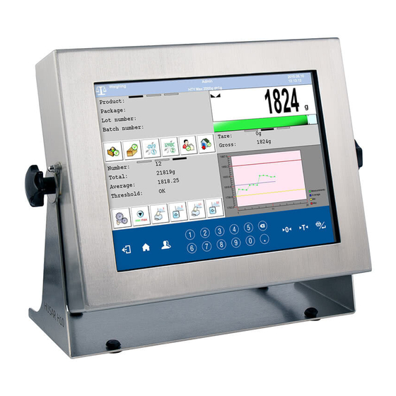
1. INTENDED USE PUE HY10 weighing indicator is a device intended to be a part of construction of industrial scales based on load cells and electromagnetic modules. The PUE HY10 is equipped with stainless steel housing of IP 68/69 ingress protection. -
Page 6: Maintenance
Before using the cleanser for all surfaces we recommend carrying out tests. Do not use cleansers containing abrasive substances. 4. MECHANICAL DESIGN 4.1. Dimensions PUE HY10 indicator, overall dimensions... -
Page 7: Connectors
4.2. Connectors PUE HY10 indicator, connectors Grounding terminal. Power cord cable gland. USB A connector. USB M12 4P connector. RS232(1) M12 8P connector. Ethernet RJ45 connector. 4OUT M12 8P connector. 4IN M12 8P connector. Platform 1 cable gland. Platform 2 cable gland. -
Page 8: Pins Assignment
Spot intended for cable gland / additional equipment connector (Vk1, RS485, Analog OUT) – mounted depending on indicator type, by default plugged. RS232(3) M12 8P connector - optional. RS232 (2) connector. Power supply switch. 4.3. Pins Assignment Pin1 – NC Pin2 –... -
Page 9: Technical Specifications
Pin1 – IN1 Pin2 – IN2 Pin3 – IN3 Pin4 – IN4 4INPUTS Pin5 – COM Pin6 – 24VDC Pin7 – GND Pin8 – NC 4.4.1. Technical Specifications Output parameters Output quantity Output type Solid-state relay Cable cross-section 0.14 - 0.5 mm Maximum output current 0.5 A DC Maximum output voltage... -
Page 10: Operation Panel
4.5. Operation Panel PUE HY10 indicator, keypad Keys Press to go back Press to enter the menu. Press to go to the home screen. Press to log in. Press to zero the scale. Press to tare the scale. Press to send the weighing result to a printer or a computer. -
Page 11: Technical Specifications
Dot character. Numeric keys. … 4.6. Technical Specifications General parameters Housing Stainless steel Ingress protection IP68 (1h max) / 69 10.1” - colour, widescreen Display 1024 x 600 + touch panel 100 240 VAC 50 60 Hz Power supply External, 12 24 VDC Optional power supply -10 °C ÷... -
Page 12: Indicator Installation
Extra options 12IN/12OUT – cable gland 12IN module Analog outputs modes: 4 - 20 mA, AN module 0 - 20 mA, 0 - 10 V (cable gland) 1 × M12 5P connector, B-codded, DP SLAVE PROFIBUS module PROFINET module 1 x hermetic RJ45 connector RS232 interface 1 x hermetic M12 8P connector RS485 interface... -
Page 13: Top Bar
Home screen layout: Detailed instruction on how to configure the home screen is to be found in „PUE HY10 Indicator Software Manual”. 6.1. Top Bar The top bar displays the following information: Working mode name and symbol. Login entry. Symbol informing that communication with a PC is on. -
Page 14: Operating The Menu
7. OPERATING THE MENU Due to a colour display and a touch panel, operation of the HY10 indicator menu is intuitive and simple. 7.1. Operation Panel Press to go to the menu. Press to go to the home screen directly. Press to go to the home screen directly. -
Page 15: Return To Weighing
8. INSTALLER INSTRUCTION The PUE HY10 indicator can be a base component of a load cell scale. 8.1. Connecting Platform Equipped With 6-Wire Load Cells 6-wire load cell connection... -
Page 16: Connecting Platform Equipped With 4-Wire Load Cells
Radwag A/D converter board Load cell signals NOTES SHIELD REF+ SENSE + JP3 not to be soldered REF- SENSE - JP4 not to be soldered OUTPUT+ OUTPUT- INPUT+ AGND INPUT- 8.2. Connecting Platform Equipped With 4-Wire Load Cells 4-wire load cell connection... -
Page 17: Connecting Signal Cable's Shield With The Platform
8.3. Connecting Signal Cable's Shield With the Platform To ensure correct scale operation, follow the below instructions regarding connection of the load cell's signal cable shield. The rules are valid for 6- and 4-wire cables. Scale with indicator Scale of a compact mechanical a metal housing, the indicator design metal... -
Page 18: Factory Setup Access
Weighing platform quantity. Declaring type of the weighing module Weighing module type Standard connecting with the indicator (read section 11). Declaring whether the scale is verified Verified or not. Request modules Enabling/disabling pairing of modules pairing connecting with PUE HY10 indicator. - Page 19 Enabling/disabling modifications „Parts Counting” mode for verified NTEP scales (USA market). 6.25, 12.5, 25, 50, Converter speed Converter rate change. Determining gravitational correction g-cor. value (read section 9.7). Serial number Serial number of the scale. Additional Profibus, Profinet, Enabling/disabling additional communication Analog module communication module.
-
Page 20: Factory Parameters
Setting default scale configuration Set default scale (button functions, printouts, text configuration information). Reset to factory Restoring default global settings. default settings 9.3. Factory Parameters NAME DEFAULT VALUES DESCRIPTION Metrology Metrology related settings Rounding of the last digit and position 0,001 ... -
Page 21: Metrological Data
VALUES DESCRIPTION NAME Enabling/disabling display of metrological data in Activation Yes, No the top bar of the home screen. PUE HY10, Selecting scale type, the scale type is conditioned Scale type HTY, HRP by an indicator type. Special name and/or... -
Page 22: Factory Adjustment
9.5. Factory Adjustment 9.5.1. External Adjustment Enter < Factory/ Adjustment> submenu and go to < Adjustment> parameter. Unload the platform. Message <Unload the platform> is displayed. Press button. Start mass is determined, message <Start mass determination> is displayed. ... -
Page 23: Linearity Correction
9.6. Linearity Correction 9.6.1. Linearity Determination Determining mass for each step of the linearity and corrections via scale software. Procedure: Enter < Factory/ Linearity> submenu and go to <Determine> parameter. <Mass> dialog box and an on-screen keyboard opens. Unload the platform. ... -
Page 24: Deleting Linearity
determined by gravitational acceleration method, determined by latitude method. 9.7.1. Entering the Gravitational Correction Value The gravitational correction value must be entered with reference to tables prepared by „Radwag Balances and Scales” or calculated using the below formula:... -
Page 25: Gravitational Acceleration Method
uzyt. cor. kal. If the scale is calibrated at the place of use then the gravitational correction value (<g-cor.> parameter) is 1.00000. If the scale is calibrated away from the place of use (longitudinal change) the value of <g-cor.> parameter must be corrected. -
Page 26: Latitude Method
Press button to confirm, the newly calculated gravitational correction value is automatically attributed to <g-cor.> parameter of < Factory / Metrology> submenu. Return to weighing, saving changes. 9.7.3. Latitude Method The method consists in automatic calculation of value of gravitational correction, <g-cor.>, on the basis of: ... -
Page 27: Declaring Verified Scale
9.8. Declaring Verified Scale Some special functions of the program are restricted for verified scales. <Verified> parameter has been introduced in order to automatically lock access to the restricted functions. <Verified> parameter must be set to <No> value for users who do not need to use verified scale, with this their device functionality is boosted. - Page 28 12IN/12OUT module 10.1.2. 12IN/OUT Schematic Diagrams 12 inputs 12 outputs...
-
Page 29: 4In/4Out Module
10.1.3. Input / Output Signals The signals are sent via 16x0.5 mm cable with numbered wires. INPUTS OUTPUTS Wire number Signal Wire number Signal OUT1 OUT2 OUT3 OUT4 COMM1 COMM1 OUT5 OUT6 OUT7 OUT8 COMM2 COMM2 OUT9 IN10 OUT10 IN11 OUT11 IN12 OUT12... -
Page 30: An Analog Output Module
10.2.2. 4IN/4OUT Schematic Diagram 4 inputs 4 outputs 10.2.3. Input / Output Signals INPUTS OUTPUTS WIRE NUMBER SIGNAL WIRE NUMBER SIGNAL OUT1 OUT2 OUT3 OUT4 COMIN COMOUT GNDIN GNDOUT +24 VDC +24 VDC 10.3. AN Analog Output Module AN module operates in three different modes: ... - Page 31 10.3.1. AN Module Configuration The module’s working mode is set using S1 switch, when setting the module's working mode refer to the below table. Analog output module board provides description of settings, for the description look around S1 switch. WORKING MODE 0-10V 4-20mA 0-20mA...
-
Page 32: Additional Platform Module, Dp6
Maximum load cell impedance Load cell power supply Load cell wiring 4 or 6 wires + Shield Multi-range option 10.4.2. Colours of Weighing Platform's Signal Wires RADWAG Marking of terminals (solder pads) on RADWAG Colour Markings A/D converter boards +INPUT brown -INPUT... -
Page 33: Rs485 Module (309R)
Module of an additional A/D DP6 converter* 10.5. RS485 Module (309R) The PUE HY10 indicator can be equipped with RS485 interface (option). This requires installation of 309Rxxxx board in U1 socket of the universal communication modules board (385Rxxxx board, ver. B). -
Page 34: Profinet Module
The modules are installed interchangeably in the same socket of the main board, 483R 10.7. PROFINET Module The PUE HY10 indicator can be equipped with PROFINET interface (option). This requires installation of AB6005 Anybus-IC module (Elmark Automatyka) in U1 socket of universal communication modules board (386R board). -
Page 35: Additional Modules Positioning
Position of PROFINET module on 386R board The indicator is equipped with an additional RJ45 connector with PROFINET description. For detailed description of PROFINET interface settings read the „PUE HY10 Indicator Software Manual”, and for communication protocol description read the „PROFINET Communication Protocol User Manual”. -
Page 36: Exclusions Regarding Installation Of Additional Modules
Additional platform DP6 11. ANNEX A - Communication with Modules Taking Function of an Additional Weighing Platform In order to declare type of a weighing module connecting with the PUE HY10 indicator go to: < Global> submenu. Weighing module's transmission parameters (baud rate,... - Page 37 Refresh * the associated device. *) - Transmission parameters of PUE HY10 indicator must be compatible with the associated device. To set transmission parameters of PUE HY10 go to „SETUP/ Communication” submenu. Set respective parameter values and return to weighing, saving changes.
-
Page 38: Communication With Mw-01 Weighing Module
RS232 or Ethernet interface. Procedure: Connect the MW-01 module to the PUE HY10 indicator using RS232 or Ethernet cable (conditioned by model), and switch both devices on. Enter global parameters submenu of the PUE HY10 indicator. - Page 39 In order to set transmission parameters for MW-01 weighing module it is necessary to put a jumper onto the module's main board: Procedure: Make sure that communication between the PUE HY10 and the MW-01 is established, enter factory parameters submenu of the PUE HY10 indicator.
- Page 40 (read section 11.2.2). Make sure that communication between the PUE HY10 and the MW-01 is established, and enter factory parameters submenu of the PUE HY10 indicator.
- Page 41 Miscellaneous Miscellaneous parameters. Group parameters communication Pue7: Communication between PUE HY10 indicator and MW -01 module (read section 11.2.1). Group of parameters enabling modification of transmission parameters for MW -01 module MW-01: Communication using PUE HY10 indicator (read section 11.2.1).
-
Page 42: Communication With Hrp Weighing Module
RS232, RS485 or Ethernet interface. Procedure: Connect the HRP module to the PUE HY10 indicator using a dedicated RS232, RS485 or Ethernet cable (list of connection cables is to be found in service manual of the HRP module). - Page 43 SW1 switch on the main board of the module. Follow HRP service manual. Make sure that communication between the PUE HY10 and the HRP is established, and enter factory parameters submenu of the PUE HY10 indicator.
- Page 44 SW1 button on the main board of the module. Follow HRP service manual. Make sure that communication between the PUE HY10 and the HRP is established, enter factory parameters submenu of the PUE HY10 indicator.
- Page 45 Verified Declaring whether the scale is verified or not. Yes, Adjustment Adjustment process. Determining start mass module Start mass determination (procedure analogous procedure described in section 9.5). HRP module adjustment (the procedure is Adjustment likewise to the one described in section 9.5). Factory adjustment procedure carried out with Internal adjustment the use of an internal adjustment weight.
- Page 46 Single w/o Type hysteresis; Single Parabolic linearity type. with hysteresis Coefficient A Parabolic linearity coefficient A. Coefficient B Parabolic linearity coefficient B. experimentally determined value that approximates parabola for loads exceeding Multiplier maximum mass of a weight used during the procedure.
-
Page 47: Diagrams Of Connection Cables
Procedure: Enter <Info / Paired modules / Pair modules> submenu. The HRP platform is automatically paired with the PUE HY10 indicator, message <Modules paired> is displayed. Press button to confirm. Serial number of the paired HRP weighing platform is displayed. - Page 48 Indicator - printer cable (EPSON) Indicator - printer cable (ZEBRA) USB adapter cable...
- Page 49 Indicator – barcode scanner cable (LS2208) Indicator – PRINT, TARE, ZERO, STOP cable Indicator - IN/OUT cable „Scale-Ethernet” cable is a standard network cable terminated with RJ45 connectors on both ends.
Need help?
Do you have a question about the PUE HY10 and is the answer not in the manual?
Questions and answers