RADWAG PUE HY10 User Manual
Hide thumbs
Also See for PUE HY10:
- User manual (26 pages) ,
- User manual (50 pages) ,
- Quick start manual (13 pages)
Table of Contents
Advertisement
Quick Links
Advertisement
Table of Contents

Related Manuals for RADWAG PUE HY10


Summary of Contents for RADWAG PUE HY10
- Page 1 PUE HY10 WEIGHING INDICATOR USER MANUAL ITKU-88-03-08-17-EN www.radwag.com...
- Page 2 AUGUST 2017...
-
Page 3: Table Of Contents
Table OF CONTENTS 1. INTENDED USE ..............................9 2. PRECAUTIONARY MEASURES ........................9 2.1. Precautions..............................9 2.2. Operation in a strong electrostatic field......................9 2.3. Scale washing ............................10 3. WARRANTY CONDITIONS ..........................11 4. UNPACKING AND MOUNTING........................12 5. WEIGHING INDICATOR STRUCTURE ......................13 5.1. - Page 4 16.4. Barcode scanner ............................43 16.4.1. Port for barcode scanner ......................43 16.4.2. Prefix / Suffix ..........................44 16.4.3. Field selection ..........................44 16.4.4. Test ............................... 46 16.5. Transponder card reader ......................... 47 16.5.1. Com port for transponder card readers ..................47 16.5.2.
- Page 5 24. SPECIAL FUNCTIONS OF WORKING MODES ................... 86 24.1. Working modes accessibility ........................87 24.2. Save mode ............................... 88 24.3. Down-weighing ............................88 24.4. Checkweighing ............................89 24.5. Tare mode ..............................89 24.6. Labelling mode ............................90 24.6.1. Setting of the number of labels to print ..................91 24.6.2.
- Page 6 30.11.1. Abort of control - procedure ...................... 148 30.11.2. Procedure of control completion ....................149 30.12. Simultaneous carrying out two control processes ................150 30.13. Report from estimating average tare ....................151 30.14. Report from product testing ........................153 31. WORKING MODES – DENSITY ........................155 31.1.
- Page 7 35.2. Deleting older data ..........................198 35.3. Weighment date search ......................... 198 35.4. Reports from weighment records ......................199 35.4.1. Filtering............................199 35.4.2. Report printout ..........................200 35.4.3. Weighments chart ........................201 35.4.4. Export a database to a file ......................202 35.4.5.
- Page 8 39. COOPERATION WITH PERIPHERAL DEVICES ..................246 40. OPTIONAL EXTENSIONS MODULES ......................247 40.1. Additional I/O module ..........................247 40.1.1. 12IN/12OUT module: technical specifications ................247 40.1.2. 12IN/OUT schematic diagrams ....................248 40.1.3. Inputs/Outputs signals overview ....................249 40.2. 4IN/4OUT – 4IN ............................. 249 40.2.1.
-
Page 9: Intended Use
1. INTENDED USE PUE HY10 weighing indicator is designed to be a component of industrial scales operation of which is based on load cells. It features stainless steel housing with IP 68/69, with thus high IP rate it can be operated within wide temperature range: -10 C –... -
Page 10: Scale Washing
2.3. Scale washing Weighing platforms are made of stainless steel (according to standards PN–0H18N9, EN-1.4301, AISI–304) and silicon elements. There is an exception, zinc coated overhead scales and painted livestock scales made of mild constructional steel with aluminium cover plate on the platform, polyester overlays and stainless steel or polyamide glands. -
Page 11: Warranty Conditions
Taken off pan 3. WARRANTY CONDITIONS A. RADWAG is obliged to repair or change those elements that appears to be faulty because of production and construction reason, B. Defining defects of unclear origin and outlining methods of elimination can... -
Page 12: Unpacking And Mounting
C. RADWAG does not take any responsibility connected with destructions or losses derives from non-authorized or inappropriate (not adequate to manuals) production or service procedures, D. Warranty does not cover: • Mechanical failures caused by inappropriate maintenance of the device or failures of thermal or chemical origin or caused... -
Page 13: Weighing Indicator Structure
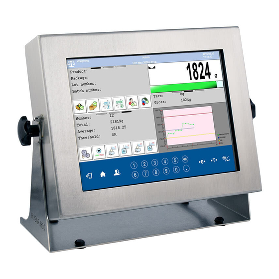
5. WEIGHING INDICATOR STRUCTURE 5.1. External view 5.2. Main dimensions PUE HY 10 indicator dimensions... -
Page 14: Description Of Connectors
5.3. Description of connectors Sockets in PUE HY10 1. Ground connector. 2. Power cord gland. 3. USB A connector. 4. USB M12 4P connector. 5. RS232(1) M12 8P connector. 6. Ethernet RJ45 connector. 7. 4WY M12 8P connector. 8. 4WE M12 8P connector. -
Page 15: Connectors' Pins Layout
5.4. Connectors’ pins layout Pin1 – NC Pin2 – RxD Pin3 – TxD Pin4 – NC RS232 Pin5 – GND Pin6 - +5VDC Pin7 – GNDZ Pin8 – 24VDC Pin1 – NC Pin2 – A PROFIBUS IN Pin3 – NC (male) Pin4 –... -
Page 16: Inputs/Outputs
5.5. Inputs/Outputs Standard version of the indicator features 4 optoisolated inputs and 4 solid- state relay outputs. Signals are fed through M12 8P connectors. Pin1 – OUT1 Pin2 – OUT2 Pin3 – OUT3 Pin4 – OUT4 4OUTPUTS Pin5 – COMM Pin6 –... -
Page 17: Inputs/Outputs Schematic Diagram
5.5.2. Inputs/Outputs schematic diagram 4 inputs 4 outputs 6. GETTING STARTED • At the back of the indicator housing find an ON-OFF switch, press it, Windows system starts loading, • When the loading procedure is completed the main software window appears. -
Page 18: Functions Of Keys
8. FUNCTIONS OF KEYS Description Press to move one level up Press to enter balance menu or to get back to the home screen Press to log in Press to zero the balance Press to tare the balance Press to send the indication to a printer or to a computer Numeric keys …... -
Page 19: Program Structure
9. PROGRAM STRUCTURE The main menu has been divided into twelve functional groups. In every group there are parameters of similar use. Pictogram Description Scale Databases Reports Working Modes Communication Devices Display Inputs / Outputs Authorization Units Other User Adjustment Info Update Remote desktop... -
Page 20: Indicating Window
10. INDICATING WINDOW Main view: In the main application window one can see two separate parts: • Top bar, • Workspace. 10.1. Top bar The top bar on the display contains the following data: Pictogram and name of an active working mode Logged user Pictogram of an active connection with a computer Symbol for active connection with E2R SYSTEM... -
Page 21: Workspace
Device name Date and time 10.2. Workspace Under the top bar, there is a workspace comprising four programmable screens for each working mode. For detailed information on screen components read section 17.1 of this user manual. 11. LOGGINGG IN In order to get full access to users parameters and to be able to edit database the user must log as an <Administrator>. -
Page 22: Logging Out Procedure
11.2. Logging out procedure • Go to the main screen and press button, operators database window opens, • Press Logging out button situated in the top bar of the operators’ database window: • The program returns to the main window and in the top bar the operators name is substituted by <Log in>. -
Page 23: Navigating Within The Menu
1. Authorization level for editing functions: • < Printouts> in submenu „ Devices / Printer”, • < Sample> in submenu „ Devices / Additional display”, • < Displaying template> in submenu „ Display / Text information”, • < Date and Time> in submenu < Others>, The functions are declared in submenu <... - Page 24 Menu list „up” Menu list „down” Scrolling „up-down” Enter (OK) Abort Add a new item in a database Disabling the formerly selected record e.g. Logging out the operator Searching a database by date Searching a database by name Searching a database by code Printing on item from a database Exporting reports from testing and average tare (for testing pre-packages mode PGC)
-
Page 25: Return To Weighing
12.2. Return to weighing Changes made to the scale’s settings are automatically saved in the memory on returning to the main software window. The scale provides two ways of returning to the main window: • By pressing key for a few times until returning to the main window, •... -
Page 26: Zeroing
• Do not apply concentrated forces (all load in one point): • Avoid side loads, particularly side strokes: 13.2. Zeroing In order to zero the indication choose a platform on the touch panel and press . After zeroing is performed the indication is equal zero and following symbols usually appear: Zeroing is possible only when the indication is stable. -
Page 27: Tarring
13.3. Tarring In order to tare the scale choose a platform on the touch panel if necessary, put a package on the pan and press . You will see the indication equal zero and following symbols usually appear: Net and After placing a load on the weight pan net mass will be shown. -
Page 28: Toggling Between Weighing Units
Switching between the II range and I range is automatic both in the switching point the autozero zone. While in AUTOZERO – pictogram appears. Then pictogram is off and a scale returns to weighing in the I range. 13.5. Toggling between weighing units Operators can change the weight unit in two ways: •... -
Page 29: Scale Parameters
14. SCALE PARAMETERS Users can set the scale according to the ambient conditions (filtering level) or own needs (autozero) and set the LO threshold for minimum load that enables operation of some functions. This parameters are placed in < Weighing>. In order to enter submenu <... -
Page 30: Filter
14.2. Filter This filter is intended to suppress continuous mechanical vibrations at the cost of stabilization time. Procedure: • Enter < Weighing> according to ch. 14 of the manual, select < Filter> and then set an appropriate value. Accessible settings: None, V.Fast, Fast, Average, Slow. -
Page 31: Minimum Weight For Different Functions (Lo)
14.4. Minimum weight for different functions (LO) Parameter <LO THRESHOLD> is associated with automatic weighing. Next weighing will not be saved until the indication goes under the THRESHOLD LO (net). Procedure: • After entering < Threshold Lo> according to ch. 14 of this manual a keyboard is displayed, •... -
Page 32: Communication
15. COMMUNICATION The scale can communicate with external devices via different ports: • RS232 (1), • RS232 (2), • Ethernet, • TCP, • Wi-Fi *. *) – Option The communication can be configured in parameters’ group < Communication>. In order to enter < Communication>, press and then „... -
Page 33: Ethernet Setting
15.2. ETHERNET setting Procedure: • Enter < Communication> according to ch.15 of the manual, select < Ethernet> and then set an appropriate value. Following settings are accessible for Ethernet: • DHCP Yes – • IP Address - 192.168.0.2 • Subnet Mask - 255.255.255.0 •... -
Page 34: Wi-Fi
• Enter the required number and press Caution: The number of TCP port in RADWAG instruments is set to default value: 4001. 15.4. Wi-Fi 15.4.1. Wi-Fi network status In order to view selected network parameters click <Network Status> field. -
Page 35: Transmission Parameters
Procedure: • Enter < Communications> parameter group as described in chapter 15 of this manual, • Go to < Wi-Fi / Available networks> submenu and select determined network out of the list, • In order to search for available networks again, select < Refresh>... -
Page 36: Devices
3. When setting <DHCP> parameter to value and restarting the device, the remaining parameters are characterized with <Read only> attribute. • With modifications carried out press button, the following message is displayed <Restart to apply the changes>, • Enter weighing mode and restart the device. 16. -
Page 37: Computer Address
16.1.2. Computer address Procedure: • Enter < Devices> parameter group as described in chapter 16 of the manual, • Choose „ Computer / Address” then the window <Address> with the screen keyboard appears, • Enter the required address and confirm it by pressing 16.1.3. -
Page 38: Cooperation With "E2R System
Procedure: • Enter < Devices> parameter group as described in chapter 16 of the manual, • Choose „ Computer / Weighing Printout Template” then the editing field <Weighing Printout Template> with the screen keyboard appears, • Modify the template if necessary and confirm the changes by pressing Caution: There are additional buttons in the bottom line of the screen keyboard. -
Page 39: Printer
Procedure: • Enter < Devices> parameter group as described in chapter 16 of the manual, • Choose „ Computer / E2R System / System is active” and then set an appropriate value. Accessible settings: System is not active System is active •... -
Page 40: Printer Port
16.2.1. Printer port Procedure: • Enter < Devices> parameter group as described in chapter 16 of the manual, choose „ Printer / Port” and then select an appropriate option. Printers can be attached to: • RS232 (1), • RS232 (2), •... - Page 41 • Modify the template according to your requirements and confirm it by pressing Caution: There are additional buttons in the bottom line of the screen keyboard. They can be used while modifying a printout template.: Screen keyboard on/off Reading a printout template from a *.lb file (button active while connecting a USB pendrive) Saving printout template in a file format *.lb (option enabled on plugging a portable data storage device to scale port)
-
Page 42: Printouts Activation
Exit Ticket Printout Template See ch. 33.5 Control Weighing Ticket Printout Template See ch. 33.5 Vehicle Scales Report Printout Template See ch. 33.5 Product Printout Template {50} {51} Operator Printout Template {75} {76} Client Printout Template {85} {86} Warehouse Printout Template {130} {131} Package Printout Template... -
Page 43: Barcode Scanner
16.4. Barcode scanner The balance allows for cooperation with a barcode scanner. The scanner can be used for quick search of: • Products, • Operators, • Clients, • Packages, • Warehouses, • Dosing process, • Formulation, • Universal variables, • Lot number, •... -
Page 44: Prefix / Suffix
Caution: A special protocol is required in order the code be received by RADWAG equipment. It is required to program an appropriate prefix and suffix. Prefix – one byte 01 hexadecimal form, suffix one byte 0D hexadecimal form. - Page 45 Source warehouse Target warehouse Dosing process Formulation Universal variable 1 Universal variable 2 Universal variable 3 Lot number Batch number • Select an item and then you can edit following parameters: Declaring an item, according to which searching Filtering is supposed to be performed Setting the first significant character in code from Offset which the comparison with items is performed during...
-
Page 46: Test
Start marker Start marker declaration End marker End marker declaration Inventory of items to be selected for filtering: Record Item for filtering Product None, Name, Code, EAN Code Operator None, Name, Code Client None, Name, Code Package None, Name, Code Source warehouse None, Name, Code Target warehouse... -
Page 47: Transponder Card Reader
• After scanning the code is entered to the ASCII field and HEX filed and at the bottom of the window a test result is displayed. When: • <Prefix> and <Suffix> declared in settings are the same as <Prefix> and <Suffix> in the read code then the test result is <Positive>, •... -
Page 48: Procedure Of Attributing The Card Number To An Operator
16.5.2. Procedure of attributing the card number to an operator To use a transponder card to log on an operator the card needs to be ascribed to the operator in the database of operators. Procedure: • Connect the transponder card reader to the required communication port (RS 232 (1) or RS 232 (2)), •... -
Page 49: Communication Protocol Frame
16.6.2. Communication protocol frame Weighing indicator with following displays: • WD display, • WWG display. To start cooperation of scales with displays go to parameter < Sample> and define an appropriate communication protocol. Procedure: • Enter parameters’ group < Devices> according to ch. 16 of this manual, •... -
Page 50: Communication Port
Caution: For detailed overview of memory map and of variables of Modbus RTU communication protocol go to chapter 38 of this manual. 16.7.1. Communication port Procedure: • Enter < Devices> parameter group as described in chapter 16 of this manual, select „ Modbus RTU / Port”... -
Page 51: Display
Procedure: • Enter parameters’ group < Devices> according to ch. 16 of this manual. • Select „ Advanced settings / Number of printers”, next set demanded number of printers (1, 2 or 3). • < Devices> parameters group will automatically be extended with new positions. -
Page 52: Display Components
17.1. Display components Workspace of the display comprises four programmable screens for each working mode: Notice: „PGC”, „SQC”, „Vehicle scale” modes are exception to the rule, for these modes it is possible to program screens 2 and 4 exclusively. < Display components>... - Page 53 Each programmable screen comprises the following components: • mass, • bargraph, • workspace, • buttons, • chart, • databases *. *) – component intended for screen 1 and 2 exclusively: • Component declared for screen 1 is automatically displayed within area of screen 1 and 3, •...
-
Page 54: Mass
• “Chart” Combining programmable screen 1 and 2 Combining programmable screen 3 and 4 • “Workspace” Combining programmable screen 1 and 2 Combining programmable screen 3 and 4 Combining programmable screen 1 and 3 Combining programmable screen 2 and 4 •... -
Page 55: Text Strings
17.3. Text strings In < Text information> users can set: Display template Data displayed in the workspace. Left displaying template Detailed description in point 17.3.1. Right displaying template Font Submenu on font settings. Changing font type for text data Type displayed in the workspace. - Page 56 The upper section of the workspace comprises a graphic information on which of the three templates is enabled. Changing of the template is carried out by dragging the workspace to the right or left. Change of the displaying template is carried out in submenu: “...
-
Page 57: Function Keys
17.4. Function keys < Button functions> submenu is designed to enable screen buttons programming. The buttons are programmed individually for each of the working modes. Particular button gets activated when a specified function is assigned to it. The button stays inactive when no function is assigned to it. Procedure: •... -
Page 58: Bargraph Type
17.5.1. Bargraph type To declare bargraph type go to: “ Display / Bargraph” / Bargraph Type” submenu. Accessible bargraphs: • None (Bargraph is not displayed), • Fast weighing, • Signalling checkweighing ranges, • Linear, • Control *. *) – intended for „PGC” and „SQC” working modes exclusively, remaining bargraph types for these mode are inaccessible. -
Page 59: Bargraph "Signalling Of Checkweighing Ranges
Means of operation: • The bargraph consists of 8 red fields and three green fields. • The green fields signal weighings between MIN and MAX threshold, where: MIN = the minimum threshold of acceptable weighing - LO MAX = the maximum threshold of acceptable weighing - HI •... -
Page 60: Bargraph Type: „Linear
Stable – signalling of OK thresholds is previewed on exceeding LO threshold and OK threshold working mode reaching stable measurement result; Unstable – signalling of OK thresholds is previewed on exceeding LO threshold Colour selection for signalling MIN threshold. Min threshold signalling colour 18 colours palette available. -
Page 61: Control" Bargraph
Colour selection for signalling MIN Min threshold signalling colour threshold. 18 colours palette available. Colour selection for signalling OK OK threshold signalling colour threshold. 18 colours palette available. Colour selection for signalling MAX Max threshold signalling colour threshold. 18 colours palette available. Background colour selection for MIN, Min Max range background colour MAX range of the bargraph. - Page 62 Means of operation: The bargraph features signalization points of: • Nominal mass Qn declated for a product, • MIN, MAX thresholds – if such are declared, • Mass value for Qn-T, • Mass value for Qn-2T, • Mass value for Qn+T, •...
-
Page 63: Inputs / Outputs
• Signaling mass above the set value of Qn+2T: Caution: In case of additional declaring the values for MIN, MAX limits, the “control” bargraph refers to the MIN, MAX limits and the nominal mass, but without displaying the errors for T and 2T. 18. -
Page 64: Configuration Of Outputs
18.2. Configuration of outputs Ascribing a function to the output enables the output at the same time. If an output has no ascribed function it is disabled. Procedure: • Enter < Inputs / Outputs> according to ch. 18 of this manual, •... -
Page 65: Authorization
PGC – pending Signal for awaiting for PGC control control *) Not applicable to „Standard” software. • Choose the required function from the list and return to weighing saving the changes according to ch. 12.2 of this manual. Caution: By default all outputs have no function attributed – setting <None>. 19. -
Page 66: Date And Time
19.2. Date and time Default settings allow a logged-in Administrator to change settings of date and time. Software however allows to change the access level to this option: < Date and time>. Procedure: • Enter parameters’ group < Authorization> according to ch. 19 of the manual, choose <... -
Page 67: Databases Edition
19.4. Databases edition It is possible to set the access levels to the following databases: • Database of Products, • Database of Clients, • Database of Formulations, • Database of Dosing processes, • Database of Packages, • Database of Warehouses, •... -
Page 68: Set Element From The Database
Procedure: • Enter parameters’ group < Authorization> according to ch. 19 of the manual, choose: „ Databases edition / Delete older data”, and then set the parameter. Accessible authorization levels: None, Operator, Advanced Operator, Administrator. 19.6. Set element from the database The user may set authorization levels for scales operator when it comes to selection of particular database positions by the operator: •... -
Page 69: Pgc
19.7. PGC The user may set authorization levels when it comes to modification of the following local parameters values of < PGC> operating mode: • Batch number, • Number of batches, • Number of samples, • Average tare estimation, • Tare, •... -
Page 70: Start Unit
Procedure: • Enter submenu < Units> in accordance with ch. 20 of this user manual, • Select option < Accessibility> which opens a window with a list of available weighing units with their accessibility attribute. Where: - Weighing unit enabled - Weighing unit disabled •... -
Page 71: User Defined Units
20.3. User defined units An option only for non-verified scale Procedure: • Enter submenu < Units> in accordance with ch. 20 of this user manual, • Select option < Defined unit 1> and determine the values of the following parameters: Multiplier Multiplier of scale’s adjustment unit Name... -
Page 72: Other Parameters
21. OTHER PARAMETERS There is a group of parameters different from others which influence the operation of the scale. They are gathered in group < Others> e.g. language, beep etc. To enter < Others>, press and then „ Others”. 21.1. Languages Procedure: •... -
Page 73: Sound Signal
Icon Name Value Description Selection of date format. Possible values: d.M.yy, d.M.yyyy, d/M/yy, dd.MM.yy, dd.MM.yyyy, dd.MMM.yyyy, dd/MM/yy, Date format yyyy.MM.dd * dd/MM/yyyy, dd-MMM-yy, dd-MM-yy, M/d/yy, M/d/yyyy, MM/dd/yy, MM/dd/yyyy, yy/MM/dd, yy-M-dd, yy-MM-dd, yyyy.MM.dd, yyyy-M-dd, yyyy-MM-dd. Selection of time format. Possible values: H.mm.ss, H:mm:ss, H-mm-ss, HH.mm.ss, HH:mm:ss, HH-mm-ss, H.mm.ss tt, Time format... -
Page 74: Screen Brightness
21.4. Screen brightness Scale user can change brightness of the screen in the range between 0% and 100%. Caution: The default screen brightness is set to 90%. Procedure: • Enter submenu < Other> as described in chapter 21 of this manual. •... -
Page 75: Screen Timeout
21.6. Screen timeout The user can specify how much time it shall take before sleep mode activates. By default the value is set to 0[s] (parameter inactive). Procedure: • Enter submenu < Others> according to ch. 21 of this manual. •... -
Page 76: Permissible Quantity Of Unsuccessful Logging
21.8. Permissible quantity of unsuccessful logging The program features option for locking particular operator logging, the operator is locked after specified number of logging operations has been performed by him/her. Procedure: • Enter submenu < Others> according to ch. 21 of this manual, •... -
Page 77: Error Information Preview Time
Procedure: • Put a memory stick into USB port of a scale, • Enter submenu: „ Others / Start logo” according to ch. 21 of this manual, • Enter < Start logo> to open content of a memory stick main folder, •... -
Page 78: Export / Import Of Settings
21.12. Export / import of settings The user can export/import scale settings (printout templates, user parameters) using flash memory stick. Procedure for settings export: • Connect flash memory stick to USB port of your scale, • Enter „ Others / Export”... -
Page 79: Adjusting Procedure
22.1. Adjusting procedure • Enter submenu < User Adjustment > according to ch. 22 and select: “ Adjustment”, • After entering the parameter the following message box appears: • Take the load off the pan of platform 1, • Press button . -
Page 80: Start Mass Adjustment
• Accept the message box by pressing key and return to weighing mode. < Setting of start mass> parameter allows to adjust start mass of platform 1. Caution: Adjustment process for remaining platforms is likewise. 22.2. Start mass adjustment It is possible to adjust only a start mass, it helps to correct the start zero when the span does not change. -
Page 81: Report From Adjustment Process
• After the procedure has been completed the following message box appears: • Accept the message box by pressing key and return to weighing mode. 22.3. Report from adjustment process Parameter < Report printout> enables activating the function of automatic printout of a report from adjustment process on a printer plugged to the scale. -
Page 82: Adjustment Track Record
22.4. Adjustment track record Each completed adjustment process is automatically saved in scale’s database in submenu < Adjustment track record>. In order to enter submenu < Adjustment track record >, press key, „ User Adjustment / Adjustment track record”. Files comprising reports have names with time and date when the process was performed. -
Page 83: On-Line Updating
• Select parameter < Software version on server> which reads software version and its availability date on RADWAG server. Caution: In case of no connection with the global network Intranet or incorrect settings of Ethernet parameters, the scale displays the following message: “... -
Page 84: Update From Pen Drive
• After downloading the update press an active key which is followed by displaying a message: • Accept the message by pressing key. The indicator shall restart with update installing procedure. 23.2. Update from pen drive Procedure: • Copy file “update.hy10” containing the current software version onto the external data storage device (to the main catalogue), •... -
Page 85: Changes In Software
• Accept the message by pressing key which automatically starts the updating process. On its completion the indicator displays the following message: • Accept the message by pressing key. The indicator shall restart with update installing procedure. 23.3. Changes in software Parameter <... -
Page 86: Special Functions Of Working Modes
24. SPECIAL FUNCTIONS OF WORKING MODES Scale can operate in following work modes: Weighing Counting pieces Deviations Dosing Formulation Density Weighing animals Vehicle scale Work modes can be configured in < Working Modes>. To enter submenu < Working Modes>, press and then „... -
Page 87: Working Modes Accessibility
Parts Percent Weighing Weighing Density counting setup animals Save Mode Down-weighing Checkweighing Tare mode Labelling mode Statistics Differential weighing Min 2, Max 2 thresholds active Peak hold Information about saved measurement Ingredient weight entered manually Other special functions are related directly to a specific working mode, and they are described in further part of this user manual. -
Page 88: Save Mode
• Set accessibility attribute for each of the working modes and return to weighing mode. 24.2. Save mode Depending on setting parameter < Save Mode> users can send data from the scale to an external device. Procedure: • Enter parameters group < Working modes>... -
Page 89: Checkweighing
Procedure: • Enter parameters group < Working Modes> according to ch. 24 of this manual, • Enter the required working mode and choose < Down-weighing> and then set the required option. Accessible options: Traditional weighing Down-weighing mode 24.4. Checkweighing In case of enabling the checkweighing mode, printouts are performed only when a weighing is between MIN and MAX thresholds that have been defined before. -
Page 90: Labelling Mode
• Enter the required working mode and choose < Tare mode> and then set the required option. Options: Single Basic tare mode. The set (chosen) tare value is overwritten after entering a new value Current sum Summing up tare values of product and package together with manually entered tare. -
Page 91: Setting Of The Number Of Labels To Print
24.6.1. Setting of the number of labels to print In the parameter < Number of labels> user defines the amount of labels. They are printed on the printer connected to the weight. Procedure: • Enter parameters group < Working Modes> according to ch. -
Page 92: Automatic Triggering Of Cumulative Labels
Procedure: • Enter parameters group < Working Modes> according to ch. 24 of this manual, • Enter the required working mode and choose: „ Labelling mode / No. of CC labels”, then the editing field <No. of CC labels> with the screen keyboard is opened, •... -
Page 93: Automatic Triggering Cumulative Labels Of Cumulative Labels
Printing followed by zeroing label counter or the total mass Printing without zeroing label counter or the total mass By default setting button is accessible in the bottom part of the display but activating the button can be done in submenu: „... - Page 94 • Enter the required working mode and choose: „ Labelling mode / CC label automatic triggering / Mode” and then set the required option: None Cumulative label of cumulative labels printout is initiated by pressing Mass Cumulative label of cumulative labels printout is initiated by exceeding the value set in parameter <...
-
Page 95: Statistics
− If parameter < Mode> is set to <Number> use the screen keyboard to enter the required counter value as a threshold to trigger off printing CC labels. • Confirm the changes introduced by pressing 24.7. Statistics All statistics are continuously updated after each measurement is saved in the scale memory. -
Page 96: Local Settings
24.8.1. Local settings Local settings for < Differential weighing> function are to be accessed in submenu: „ Working modes / Weighing / Differential weighing: Activation of differential weighing function Activation - function active, - function inactive) Batch type, for differential weighing: Value –... -
Page 97: Peak Hold
Caution: The user can customize report template, to customize the template go to: „ Devices / Printer / Printouts Differential weighments reports template” (read section 16.2.3 of this user manual). Report on each completed differential weighing process is recorded in < Differential weighments>... -
Page 98: Information About Saved Measurement
24.10. Information about saved measurement The user can activate message informing on the fact that a particular weighing result has been recorded in a database, the message is displayed each time after performed measurement. Procedure: • Enter submenu < Working modes> according to ch. 24 of this manual, •... -
Page 99: Working Mode - Weighing
25. WORKING MODE - WEIGHING The < Weighing> mode is the standard working mode allowing to perform weighments and saving them in the database < Weighings / Alibi>. 25.1. Starting the working mode The < Weighing> mode is the standard working mode. If a user has changed the operating mode to another follow the actions below: •... -
Page 100: Working Modes - Parts Counting
Information abort Detailed description in ch. 24.10 of the user manual saved measurement Ingredient weight Detailed description in ch. 24.11 of the user manual entered manually 26. WORKING MODES – PARTS COUNTING Parts counting is working mode allowing to count pieces on the basis of the standard unit mass of a single piece set on the scale or fetched from the database. -
Page 101: Automatic Correction Of Reference Mass
Automatic correction Detailed description in ch. 25.2.1 of the user manual of reference mass Minimum reference mass Detailed description in ch. 25.2.2 of the user manual Save Mode Detailed description in ch. 24.2 of the user manual Down-weighing Detailed description in ch. 24.3 of the user manual Checkweighing Detailed description in ch. -
Page 102: Minimum Reference Mass
Function < Automatic correction of reference mass> in mode < Parts counting > is enabled at the moment of estimating the sample quantity and signalled by displaying <PCS> and <SMP> (single part/piece mass) on the top part of the display. There are four criteria of working “Automatic correction of reference mass”... -
Page 103: Setting A Reference Unit By Entering Known Piece Mass
Accessible settings: 1 d, 2 d, 5 d, 10 d. Caution: While the procedure of evaluation the mass of single piece the mass of all pieces put on the pan is lower than the value declared in parameter „ Minimum reference mass”, the following warning message will be displayed: <... -
Page 104: Setting The Reference Mass By Entering Single Piece Mass Directly To The Database
• Enter a value and confirm it by pressing , then the following message is displayed: <Put pieces: xx> (where xx – the value entered before), • Put the declared quantity of pieces on the pan and when the result is stable (symbol ) confirm it by pressing •... -
Page 105: Working Modes - Percent Setup (Deviations)
b) Hold your finger on a selected product from the <Products> list, context menu is displayed, c) Choose option <Ascribe standard>, then the standard unit mass is attributed to the product in the field <Mass>. Caution: Attributing a standard to a selected product is also possible by programmable button. -
Page 106: Reference Unit Mass Estimated By Weighment
Save Mode Detailed description in ch. 24.2 of the user manual Down-weighing Detailed description in ch. 24.3 of the user manual Checkweighing Detailed description in ch. 24.4 of the user manual Tare mode Detailed description in ch. 24.5 of the user manual Labelling mode Detailed description in ch. -
Page 107: Working Modes - Dosing
28. WORKING MODES - DOSING < Dosing> mode enables carrying out filling and dosing processes of goods on scales featuring an indicator PUE HY10 series. The working mode enables manual and automatic dosing on a single or simultaneously on many weighing platforms. -
Page 108: Dosing Process Structure
28.2. Dosing process structure All activities related to the dosing process can be carried out from the level of scale. Each dosing process < > contains: • Its name < >, • code < >, • assigned weighing platforms < >... -
Page 109: Description Of Functions And Setting Dosing Process
Enables an already initiated process to be Automatic cycle performed in a cyclic manner Global Global settings of doisng process Enables setting the outputs for dosing (fine Batching outputs dosing in case of two-step dosing process) Enables setting outputs for bulk dosing in Bulk batching output case of two-step dosing process Enables determining global value of... - Page 110 Mass Mass of an ingredient to be dosed Mass of an ingredient for bulk dosing Mass for fast dosing (in case of two-step dosing process) Dosing process ingredient uploaded from Product Products database Enables switching on checkweiging mode Down-weighing (weighing on minus) Function enabling setting the status of indicator’s outputs for controlling peripheral Outputs...
- Page 111 Conditional function, determining when the followwing step should be carried out, depending on status of indicator’s intput. Each input can take the following status: None – input disabled; „0” – input with low status; „1” – [CI] Input condition input with high status; „/” – input with increasing tendency (status change from low to high, e.g.: the moment of pressing a key);...
-
Page 112: Creating A New Dosing Process
Permissible error ± of dosed-out mass, given Insensibility threshold as a percentage [%] Minimal flow value given as [g/s] or [kg/s] for an Minimal flow initiated algorithm of gravitational dosing Weighing in minus Allows for turning on weighing in minus mode 28.5. -
Page 113: Instances Of Dosing Processes
28.6. Instances of dosing processes 28.6.1. Instance 1 – Manual dosing process of 4 ingredients on 2 weighing platforms Description: A dosing process contains 4 ingredients, which are weighed on two weighing platforms: • Weighing Platform 1: ingredients: Flour and Sugar •... - Page 114 [5s] Place empty Pending for loading an empty container 8. [TI] Delay container for the second product Input 1 has to take increasing tendency – 9. [CI] Input Input 1 – „/” press function key confirming loading a condition container 10.
-
Page 115: Instance 2 - Automatic Dosing Of 2 Ingredients On 2 Weighing Platforms
Checking condition, whether signal flag 1 is set to value “1” – i.e. checking whether 8. [CF] Flags desired part of the process has been already Signal flag 1 – „1” condition realized on the weighing platform no. 1. If Yes, then dosing process on the second weighing platform shall continue. - Page 116 The condition is marked with signal flags, which determine formulation making process between the weighing platforms, in a way which orders dosing Water ingredient as the second one. The whole process is described below in tables, separately for each weighing platform. Dosing process name: Instance 2 Dosing process code: 2222 Dosing process from an indicator level:...
-
Page 117: Instance 3 - Mixed Dosing Process
Platform 2 Icon Step Value Description Checking condition, whether signal flag 1 is set to value “1” – i.e. checking whether 1. [CF] Flags Signal flag 1 – desired part of the process has been condition „1” already realized on the weighing platform no. - Page 118 Dosing process is carried out manually and automatically, and it includes a condition that the dosing sequence is strictly determined – dosing of “Water” ingredient can be initiated only on completing the dosing process of ingredient “Flour” and “Sugar”. Ingredient “Seasoning” will be added as the last one to the dosing process.
- Page 119 11. [T] Tare Tare Tarring the weighing platform no. 1 12. [DH] Dose Manual weighing product Sugar to 0,4 kg [Sugar] manually obtain 0,4 kg mass [5s] Unload container Pending for unloading the container with 13. [TI] Delay with product “Sugar”...
-
Page 120: Reporting Of Completed Dosing Processes
Platform 2: Icon Step Value Description Checking condition, whether signal flag 1 is set to value 1. [CF] “1” – i.e. checking whether desired part of the process Flags Signal flag 1 – „1” has been already realized on the weighing platform no. condition 1. -
Page 121: Working Modes - Formulation
Default form of the report template on dosing template: ---------------------------------------------- Dosing process ---------------------------------------------- {40:Start date:,-25}{180} {40:End date:,-25}{181} {40:Name:,-25}{175} {40:Code:,-25}{176} {40:Status:,-25}{182} {40:Measurements:,-25} ---------------------------------------------- {185:(50,-20) (7)(11) (40:Nominal Mass:,-25)(186)(11) (40:Difference:,-25)(187)(11) ---------------------------------------------- }{40:Mass:,-25}{184}{11} ---------------------------------------------- The report from each completed process is simultaneously saved in the database of <... -
Page 122: Local Setting Of A Working Mode
Local parameters Select formulation Start formula making process Stop formula making process Select formulation ingredient from the list Set “mass from hand” – mass of an ingredient supplied in ready packaged and with determined mass 29.2. Local setting of a working mode Local settings for the working mode <... -
Page 123: Creating A New Formulation
29.3. Creating a new formulation Procedure: • Databases> from main menu Press key and select option < then select < Formulation>, • In order to create a formulation, press < Add> key, and confirm creating a new record in formulation database. List of data specified for a new formulation: Name Formulation name... - Page 124 List of data created for an ingredient of a formulation: Name Name of an ingredient in a formulation Code Code of an ingredient in a formulation An ingredient of a formulation selected from the Product database of products Mass Mass of an ingredient Declaring the deviation type: the measuring unit fo Deviation type an active weighing platform or the value in [%]...
- Page 125 3) – in case of declaring the value of the low deviation as greater than the declared ingredient mass, the software displays the following message: 4) – in case the sum of ingredients mass and the value of high deviation are exceeding the maximum capacity of a weighing platform, the software displays the following message: •...
-
Page 126: Formula Making Process
29.4. Formula making process Starting the making process requires that the authorization (access formula level) of the logged user is sufficient to start the process. Caution: 1. Starting the process requires that the logged user has access level at least of an <operator>. - Page 127 2. The inserted code of the current ingredient is incorrect, and the ingredient is not in the formulation composition. The software displays a message: <No ingredient with specified code. Abort?>. On accepting the message by pressing key the software goes to another ingredient on the list.
-
Page 128: Reporting From Completed Formula Making Processes
• If a user tries to accept the following weighed mass without changing mass of the load placed on the weighing platform, the software displays a message <Load appropriate product>, • If a user tries to accept mass of a portion while the parameter < Portion weighing>... -
Page 129: Working Mode - Pgc (Control Of Prepacked Goods)
Default form of the report template on formula making process: ---------------------------------------------- Formulation ---------------------------------------------- {40:Start date:,-25}{240} {40:End date:,-25}{241} {40:Name:,-25}{220} {40:Code:,-25}{221} {40:Status:,-25}{242} {40:Measurements:,-25} ---------------------------------------------- {245:(50,-20) (7)(11) (40:Nominal Mass:,-25)(246)(11) (40:Difference:,-25)(247)(11) ---------------------------------------------- ---------------------------------------------- {40:Mass:,-25}{244} ---------------------------------------------- The report from each completed formula making process is simultaneously saved in the database of <... -
Page 130: Starting The Working Mode
The acquired data allow for carrying out a quality control of manufactured packaged goods for: • Compatibility with the Regulation by the Central Office of Measures of 3 April 1997 on the requirements for a quality control of prepacked goods – by random selecting measurement results and sending them to the procedure of control of prepacked goods, •... -
Page 131: Control Settings Mode Window
Where: Entering control settings window Local settings for the working mode Product record of a database (name and nominal value) 30.2. Control settings mode window Caution: Before entering the control settings mode carry out Logging procedure, as described in ch. 11.1 of this manual. Press button located at the bottom of the <... -
Page 132: Local Setting Of A Working Mode
Where: Selecting product from the database Declaring number of the controlled batch Working mode local settings Returning to the working mode home screen Control start 30.3. Local setting of a working mode Local settings of the working mode < PGC> are accessible on pressing a hot-key <... -
Page 133: Editing A Product To Be Controlled
30.4. Editing a product to be controlled A product is edited in submenu “ Databases”. Caution: In case the scale cooperates with a computer software < E2R System> editing the databases from the scale level is blocked. Editing and exporting product records to the scales is carried out from the level of computer software. - Page 134 Declaring quantity of packages to be controlled Quantity of for determining average tare (for control type packages “non-destructive average tare”) Cyclic Turning on / turning off an option of displaying of cyclic estimation of average tare for a product. average tare Value of time determining frequency of tare Interval of control during a process of product control.
-
Page 135: Control Start Procedure
Average limit value (negative) for a tested sample Average limit value [ - ] (refers to average limit value as a “constant”) Average limit value (positive) for a tested sample Average limit value [ + ] (refers to average limit value as a “constant”) Standard deviation multiplier for the average limit Factor value [- Wk] value (negative) determined in the automatic mode... -
Page 136: Control Aborting Procedure
where: Abort control start Control start Caution: If before control start the operator: • Does not remove a load from the weighing pan or other criteria for zeroing are failed (e.g. unstable weighing result) the scale displays a message: <Unable to start control. Zeroing error>, •... -
Page 137: Logging Out From A Control Process In Progress
Simultaneously, a control report with status <Terminated> is added to the database of < Controls>. 30.7. Logging out from a control process in progress Procedure: • While in control mode press pictogram with name of the logged operator located in the bottom bar of the display, •... -
Page 138: Non-Destructive Average Tare Control Mode
• Pressing the button causes displaying a Logging in window <Insert Password> with the name of previously logged operator. • After entering a correct password and accepting it by pressing the scale automatically returns to the control process in progress. 30.8. - Page 139 - Average tare of a packaging in [g] - Standard deviation - Characteristics of negative errors T1 in a sample - Characteristics of negative errors 2T1 in a sample - Net mass of the controlled package - Packaging tare Status - Packaging control status Place packaging - Command on control process with quantity of all...
- Page 140 Pressing key causes moving to the control process without saving the determined average mass of a packaging in product record in the database. Pressing key causes moving to the control process with simultaneous saving the determined average mass of a packaging in product record in the database.
- Page 141 Characteristics of negative errors 2T in a sample: -30g - value of the negative error 2T Max 2T - permissible number of the negative errors 2T n 2T - actual number of the negative errors 2T Net mass of the controlled product Tare of the packaging Status Control status: positive, negative...
- Page 142 • Data on control process in progress Pressing key displays data on a control process in progress: Pressing key causes returning to the control process in progress. Pressing key causes moving to displaying a list of completed weighments: In order to return to the control process in progress press key.
- Page 143 Additionally, pressing the workspace area enables an operator to change its format (from a line chart to a bar chart): After completing the control the scale generates a process summary, and the accomplished control is automatically saved in the scale database: Pressing key causes printing a report on a printer connected to the scale.
-
Page 144: Performing Non-Distructive Testing In Mode Empty-Full
Press and then some descriptions and boundary criteria are changed. After the test has been completed the test is summarized and the results are automatically saved in the database and the report can be printed on an attached printer. Caution: A pattern and example of the report from testing products are described in ch. -
Page 145: Performing Destructive Testing In Modes Empty-Full And Full-Empty
Where: Product Name of the controlled product Code Code of the controlled product Nominal value of the controlled product Average mass of the controlled product Value of the disqualifying average Characteristics of negative errors T1 in a sample (in accordance with ch. 30.6 of the manual) Characteristics of negative errors 2T1 in a sample (in accordance with ch. -
Page 146: Control In Accordance With Internal Criteria
After selecting from a list a product with set options for the destructive control with determined measuring “lot”, and starting the control process, the software will display messages facilitating the control process (as in the case of control process described above). Depending on the set control mode, the scale orders the following sequence of weighing products: “empty-full”... - Page 147 Accept the message box by pressing key which causes moving to the control process. During control process the software carries out real-time monitoring of the measurement results and displays them it the corresponding fields of the display for informing the operator on control result: Where: Product Name of the controlled product...
-
Page 148: Abort Of Control - Procedure
Characteristics of positive errors 2T in a sample: +30g - value of the positive error 2T, Max 2T - permissible number of the positive errors 2T, n 2T - acutal number of the positive errors 2T Put Full 1/30 Command on control process Net mass of the controlled product Data on a control process in progress (in accordance with ch. -
Page 149: Procedure Of Control Completion
A report on control will be saved to < Controls> database, report’s status - <Terminated>. 30.11.2. Procedure of control completion Completion of control realized in accordance with internal criteria may be carried out in two ways: • Automatically All samples control – number of controlled samples accordant with declared value in <Sample quantity>... -
Page 150: Simultaneous Carrying Out Two Control Processes
30.12. Simultaneous carrying out two control processes The scale enables carrying out two control processes at the same time. The option is enabled in: • Go to local mode settings and set parameter < Number of accessible controls> to value 2 (two controls), •... -
Page 151: Report From Estimating Average Tare
Caution: Processes: • Control carrying out, • Logging out during control in progress, • Control termination, are the same as in case of the above parts of the manual. 30.13. Report from estimating average tare Report example: Average Tare Report U/26/09/09/10/56/T --------------------------------------- Balance Type: WPY KTP... - Page 152 Standard Deviation: 0.3162278 Test result: Positive Weighments: 1. 8.5 g 2. 7.5 g 3. 8.0 g 4. 8.0 g 5. 8.0 g 6. 7.5 g 7. 7.5 g 8. 8.0 g 9. 8.0 g 10. 8.0 g ........---------------------------------------- Report pattern: In submenu <...
-
Page 153: Report From Product Testing
30.14. Report from product testing Report example: PGC Report U/26/09/09/10/59 ---------------------------------------- Balance Type: WPY KTP Max: 1.5/3 kg d=e: 0.5/1 g Factory Number: 123589 Start date: 2009.09.26 10:55:28 End date: 2009.09.26 10:59:53 Operator: Jan Kowalski Product: AQUABA SAUCE Batch Number: 123/09 Nominal Mass: 520 g... - Page 154 Report pattern: In submenu < Printouts> users can edit the pattern of the average tare report (see ch. 16.2.3). The default pattern is shown below: PGC Report {279} --------------------------------------- {40:Balance type:,-20}{44} {40:Max:,-20}{34} {40:d=e:,-20}{33} {40:Factory number:,-20}{32} {40:Start date:,-20}{261} {40:End date:,-20}{262} {40:Operator:,-20}{75} {40:Product:,-20}{50} {40:Batch number:,-20}{260} {40:Nominal Mass:,-20}{53}{278}...
-
Page 155: Working Modes - Density
31. WORKING MODES – DENSITY Working mode < Density> enables determining density of solids, liquids and materials of high viscosity. The density is determined on basis of Archimedes principle, according to which any floating object displaces its own weight of fluid. The density mode also enables utilizing a pycnometer for determining density of liquids. -
Page 156: Carrying Out Density Determination Procedure
Ask about sample Function ordering inserting number of a sample before initiating the test procedure number Parameter designed for manual determining mass of a pycnometer expressed in [g]. If inserted value is equal Pycnometer mass to „0” then on test procedure start, the pycnometer mass shall be measured. - Page 157 Process course: • Press < Local parameters> key to enter the setting of local parameters in density mode. • Press < Sinker volume> in order to insert the volume of the sinker (given in [cm ]) which is immersed in the tested liquid. •...
-
Page 158: Determining Density Of Solids
31.3.2. Determining density of solids Density of solids is determined by weighing a solid object in two different medium: in the air and in auxiliary liquid with determined density. The difference between the two measurements is displacement weight, which is used by scale software to calculate the density of tested solid. Before starting the measurement select <... -
Page 159: Determining Density Of Pycnometer
Caution: If in the local parameters, < Ask about sample number> function is enabled, then on initiating the process, the system asks for inserting the number of tested sample. The inserted sample number is linked to the process data and saved in the database. •... - Page 160 The excess of liquid pouring through the capillary tube is removed with an absorbent paper. Then, the vessel is immediately placed on a scale, and its mass is determined as quickly as possible. During the mass measurement, due to contraction of the volume of liquid its level usually decreases in the capillary tube, but this does not matter if at the time of placing instrument on the scale, it was completely filled and had correct temperature.
-
Page 161: Determining Density Of A Porous Body
Caution: If in the local parameters, < Ask about sample number> function is enabled, then on initiating the process, the system asks for inserting the number of tested sample. The inserted sample number is linked to the process data and saved in the database. •... - Page 162 Process course: • Press < Local parameters> key to enter the setting of local parameters in density mode. • Press < Standard liquid> key to select the auxiliary liquid used for the density determination procedure. If the auxiliary liquid is other than “Water”...
-
Page 163: Reporting From Completed Density Determination Processes
• On carrying out the third measurement, the scale automatically determines the density of the porous body, and indicates the result on indicator’s display. If the user needs a report from the density determination process, it can be printed on a plugged printer by pressing key. -
Page 164: Table Of Density Parameter For Water
31.5. Table of density parameter for water T/°C 0.99973 0.99972 0.99971 0.99970 0.99969 0.99968 0.99967 0.99966 0.99965 0.99964 0.99963 0.99962 0.99961 0.99960 0.99959 0.99958 0.99957 0.99956 0.99955 0.99954 0.99953 0.99951 0.99950 0.99949 0.99948 0.99947 0.99946 0.99944 0.99943 0.99942 0.99941 0.99939 0.99938 0.99937 0.99935 0.99934 0.99933 0.99931 0.99930 0.99929 0.99927 0.99926 0.99924 0.99923 0.99922 0.99920 0.99919 0.99917 0.99916 0.99914 0.99913 0.99911 0.99910 0.99908 0.99907 0.99905 0.99904 0.99902 0.99900 0.99899 0.99897 0.99896 0.99894 0.99892 0.99891 0.99889 0.99887 0.99885 0.99884 0.99882... -
Page 165: Working Modes - Animal Weighing
32. WORKING MODES – ANIMAL WEIGHING Working mode < Animal weighing> enables weighing objects which do not stabilize if placed on scale’s weighing platform and while carrying out weighing process. Weighing process is achieved by implementing parameter of time for stability of measurement, which is set in global parameters of the working mode. -
Page 166: Carrying Out Animals Weighing Procedure
Declaration of process duration in seconds (from 1s to 90s) – measurements carried out in set time Averaging time interval are used to calculate mean value, which is the result of the measurement Operation mode, in which the scale automatically begins the following measuring process, if the load Automatic mode placed on scale’s weighing platform exceeds value... - Page 167 • Select working mode < Vehicle Scale>, the software automatically returns to the main window: Where: Select a vehicle Default transaction type Local parameters of a working mode Select an open transaction Select a product Select a client Abort an ongoing transaction...
-
Page 168: Working Mode Local Settings
33.2. Working mode local settings The local settings of working mode < Vehicle Scale> are accessed by pressing an hot-key < Local settings>: Default transaction Selecting a default transaction type. Available type settings: Entrance, Exit, Control weighment. Declaring the means for selecting a vehicle. Select vehicle Available options: From list, From hand, By name, By code. - Page 169 Procedures for carrying out an entrance transaction and an exit transaction are the same, therefore the further part of the user manual contains description of an entrance transaction only. Before starting a transaction enter to scale memory general parameters of the working mode (see point 33.2 of this user manual). Procedure: •...
- Page 170 Caution: 1. Additionally, an operator can: • Assign a product to a transaction by pressing button, • Assign a client to a transaction by pressing button. 2. Before starting a transaction, first an operator should select a vehicle to be weighed. Otherwise the scale displays a message <...
- Page 171 Confirm weighing 2 - Message for an operator. The scale waits for accepting the exit weighment 0 kg - Mass of the load • At the same time, a printer connected to the scale prints an “Entrance ticket”. Caution: A default format of an „Entrance ticket” template is described in point 33.5 of this user manual.
-
Page 172: Control Weighment Transaction
Caution: 1. In case of declaring an automatic printout of a report, on completing a vehicle transaction the scale orders printing a “Report from Vehicle Scale” together with the printout of the “Exit ticket”. 2. A default format of the printout template of the “Exit ticket” and a “Report from Vehicle Scale”... - Page 173 Where: - A vehicle with saved registration number PL 45332 - Transaction type (control weighment) Control weighment Confirm weighing 1 - A message for an operator. The scale waits for accepting the control weighment Caution: Additionally, an operator should determine: −...
-
Page 174: Open Transactions Table
Caution: The non-declared transaction items are represented by dashes, correspondingly denoting: • Missing code assigned to a vehicle, • Missing product assigned to a transaction, • Missing client assigned to a transaction, • Missing value of load mass. • At the same time, a printer connected to the scale prints a ticket “Control weighment ticket”. -
Page 175: Printout Templates For An Ongoing Transaction
Caution: If a user attempts to choose a vehicle for which a transaction is already opened, then the software displays a message box: 33.5. Printout templates for an ongoing transaction During ongoing vehicle transaction the user can print transaction tickets (reports) with the use of a printer connected to the scales. -
Page 176: Executed Transactions - Reporting
Control Weighment Ticket ---------------------------------------- Control weighment ticket Printout Template: ---------------------------------------- {40: Date:,-20}{4} {40: Vehicle:,-20}{210} {40: Mass:,-20}{7}{11} Signature......---------------------------------------- Report from Vehicle Scale ---------------------------------------- Report from Vehicle Scale Printout Template: ---------------------------------------- {40:Start date:,-20}{213} {40:End date:,-20}{214} {40:Vehicle:,-20}{210} {40:Mass on entrance:,-20}{215}{11} {40:Mass on exit:,-20}{216}{11} {40:Mass of load:,-20}{217}{11} Signature...... -
Page 177: Databases
Detailed list of data for an executed vehicle transaction – see point 35.5.7 of this manual. 34. DATABASES Scale databases hold different data: Products Operators Clients Dosing processes Formulations Vehicles Identification processes Time Schedule PGC Packages Warehouses Labels Universal variables Extra variables Images In order to enter <... -
Page 178: Database Configuration
34.1. Database configuration < Databases configuration> submenu enables the user to: • Set databases availability • Categorize product • Declare data operation for databases: product, operators, clients, extra variables • Change databases records preview • Import databases from a memory stick to the scale •... -
Page 179: Database Variables Operation
To operate product categories < Product categories> parameter needs to be activated. The parameter is located in „ Databases configuration categories” submenu. How to create databases categories – procedure: • Enter „ Databases configuration/ Categories Database of categories”, • Press button to see <Create new record?>... -
Page 180: Change Name Of An Extra Variables Database
• Choose a demanded database to view a list of variables with accessibility attribute. Where: - Accessible variable - Inaccessible variable • Set accessibility of a demanded variable and exit in order to start weighment. 34.1.4. Change name of an extra variables database The user can change a name of an extra variables chart (table) in the following cases: •... -
Page 181: Databases Export / Import
Where: - List - Tiles 34.1.6. Databases export / import The user can export/import all databases with the use of a memory stick. Database export procedure: • Put a memory stick into USB port of a scale, • Enter: „ Database configuration / Export”... -
Page 182: Quick Name Search
34.2.1. Quick name search Procedure: • Enter < Databases> according to ch. 34 of the manual, • Enter < Products>, • Press , then an editing field appears <Search by name> with the screen keyboard, • Enter the name of a product or its part and press •... -
Page 183: Deleting Items In Databases
Caution: Adding new records in databases is possible only by logged-in administrators. 34.4. Deleting items in databases Procedure: • Enter < Databases> according to ch. 34 of the manual, • Enter < Products>, • Give a long press to the item, then the context menu is displayed, •... -
Page 184: Context Menu
34.6. Context menu Context menu enables the user to a quick access to database functions. Pressing a demanded database element (submenu) for about 2 seconds is required in order to activate a context menu. Context menu for each of the databases displays the following list of functions: Where: Open... -
Page 185: Database Edit Window
34.7. Database edit window The database edition can be performed by an administrator. 34.7.1. Operators’ database Procedure: • Enter < Databases> according to ch. 34 of this manual, • Enter < Operators> and press the required position. Record of operator: Name Operator name Code... - Page 186 Product record: Name Product name Code Product code EAN code Product barcode Mass Nominal product mass Mass of an ingredient for bulk dosing Mass for fast dosing (in case of two-step dosing process) Batching outputs Declaring numbers of outputs for fine dosing Bulk batching output Declaring numbers of outputs for bulk dosing Value of dosing correction for weighing...
-
Page 187: Database Of Clients
Submenu with data declared in the working PGC mode mode PGC (see ch. 30.4 of the manual) Number of validity Number of days to calculate expiry date dates Additional days of Offset of number of days of assortment expiry expiry period date Date Constant product date... -
Page 188: Database Of Dosing Processes
Client records: Name Client’s name Code Client’s code Tax ID Client’s tax ID Address Client’s address Postal code Client’s postal code City Client’s Town/City Discount Client’s discount Label Client’s label template 34.7.4. Database of dosing processes Procedure: • Enter < Databases>... -
Page 189: Database Of Formulations
34.7.5. Database of formulations Procedure: • Enter < Databases> according to ch. 34 of this manual, • Enter < Formulations> and press the required position. List of data for a specific formulations: Name Formulation name Code Formulation code Ingredients Defining ingredients of a formulation Number of Previewing number of created ingredients in a formulation ingredients... -
Page 190: Database Of Vehicles
Cyclic control Activating cyclic control Interval [min] Specifying time interval in [min] for cyclic control 34.7.7. Database of vehicles Procedure: • Enter < Databases> according to ch. 34 of this manual, • Enter < Vehicles> and press the required position. List of data definable for a vehicle: Name * Name of a vehicle (registration number) -
Page 191: Database Of Packages
List of data for a selected identification process: Name Identification process name Code Identification process code Enables an already initiated identification process Repeat the process to be performed in a cyclic manner Submenu used for defining (creating) an Process creator identification process 34.7.9. -
Page 192: Database Of Labels
Warehouse record: Name Warehouse name Code Warehouse code Description Additional warehouse description 34.7.11. Database of labels The database comprises templates of labels which users can attribute to products or clients to operate in labelling mode. Procedure of editing databases: • Enter < Databases>... -
Page 193: Database Of Universal Variables
34.7.12. Database of universal variables The database includes templates of general purpose variables which user can attribute to screen function buttons , in order to enter any alphanumeric text intended to be printed. Additionally values of three first universal variables are stored in scales storage. -
Page 194: Images Database
Caution: Procedure of defining screen function buttons is described in point 17.2 of this manual. 34.7.14. Images database The database contains graphics that can be assigned to particular records of < Products> database. Creating a new record - procedure: • Put a memory stick into USB port of a scale, •... -
Page 195: Reports
35. REPORTS Software enables the following reports: Weighments / Alibi Reports from dosing Reports from recipes Controls Reports Average tare reports Vehicle scale reports Density reports Differential weighments reports To enter < Reports> menu press button, which is located in the window of the indicator, and choose <... -
Page 196: Reports Accessibility
35.1.1. Reports accessibility Submenu < Reports accessibility> allows for declaration of reports that are to be accessible for the user. Procedure: • Enter submenu < Reports> according to ch. 35 of this manual, • Select < Reports accessibility> to view a list of reports with the accessibility attribute. -
Page 197: Query For Number Of Weighings To Be Deleted
List of data definable for a batch number: Name Change of the batch number name Batch number template, allows using variables that Template are intended for a printout 35.1.4. Query for number of weighings to be deleted The user with Administrator permissions level can delete (undo) recently performed weighings using programmable button: <... -
Page 198: Deleting Older Data
• All of the weighings that are to be deleted refer to any kind of report (report on dosing, report on formula, report on PGC control, report on vehicle scale, report on density, report on differential weighing) then the following message is displayed <Operation not allowed. -
Page 199: Reports From Weighment Records
• Press , then an editing field appears <Specify year> with the screen keyboard, • Enter: year, month, day, hour, minute of weighing and confirm it by pressing • The program will automatically display the list of weighments putting at the top the position with the entered date. 35.4. -
Page 200: Report Printout
- lot number, - batch number, - source warehouse name, - target warehouse name, - result control, - platform number. Procedure: • Enter submenu: „ Reports / Reports From weighing records / Filtering” according to ch. 35 of this manual, •... -
Page 201: Weighments Chart
Weighing records {100: (40:Date:,-10)(4) (40:Mass:,-10)(6) (10) }---------------------------------------- {40:Number of weighments:,-20}{115} {40:Totalized weighments:,-20}{116}{11} Caution: • Submenu: „ Devices / Printer / Printout / Report From Weighments Printout Template” allows for free modification of a report template (see point 16.2.3 of this manual); •... -
Page 202: Export A Database To A File
Available options, located below the diagram: 100% zoom of a diagram Zoom out, the diagram gets back to its previous size Display the previous window Print the diagram, use a PCL type printer Save the diagram as a *.bmp file, save it to a memory stick connected to USB port 35.4.4. - Page 203 Operator Product Client Package Source warehouse Target warehouse Checkweighing Platform number Statistics: Number of measurements Weighing counter Trade settlement Vehicle Universal variable Extra variable Custom variable: Value Custom variable: Name *) – Automatic selection of data to be exported (unfilled fields are omitted) •...
-
Page 204: Counter Of Weighments Records
Caution: In case a pen drive is not recognized after entering < Export database of weighments to a file> a message is displayed: <Operation failed>. • After the operation has been completed: „Operation finished successfully” is displayed together with the file name (with extension *.txt) created on the pen drive, Caution: The file name consists of a database name and scale factory number,... -
Page 205: Reports Preview
• Enter option < Weighing counter> which opens an editing window with the value of the counter of weighing records and an on-screen numeric keyboard. • Insert desired value and accept it by pressing key. 35.5. Reports preview 35.5.1. Weighments / Alibi Procedure: •... -
Page 206: Reports From Dosing
Platform number Platform number to perform weighments Statistics: Number Statistics: Current number of measurements of measurements Weighing counter Global counter of weighment records < Trade settlement> submenu will be created automatically in a weighment record when a chosen product is being weighed. List of <... -
Page 207: Reports From Recipes
List of data for a selected report from dosing: Status Status of correctness for a completed dosing process Start date Start date of dosing process End date End date of dosing process Dosing process Name of completed dosing process Operator Operator preparing a dosing process Client Client for which the dosing process is prepared... -
Page 208: Density Reports
Number of Number of measurements within a completed Measurements formulation making process 35.5.4. Density reports Procedure: • Enter < Reports> according to ch. 35 of this manual, • Enter < Density Reports> and press the required position. List of data for a specific report from density determination process: Number of sample for which the density is Sample number determined... -
Page 209: Controls Reports
Weighing 2 Mass value of the 2 measurement Weighing 3 Mass value of the 3 measurement Value of pycnometer’s mass utilized during Pycnometer mass density determination process Value of pycnometer’s volume utilized during Pycnometer density density determination process 35.5.5. Controls reports Every control procedure performed on the scale is sent to a printer and saved in database <... -
Page 210: Average Tare Reports
Inventory of fields in every control: Batch number Batch number of tested goods Status Control Status/Result Start Date Control beginning date End Date Control finishing date Product Tested product name Operator Operator performing the test Average value of weighments Disqualifying average value Standard deviation Number of products in a batch for which a sample Batch quantity... - Page 211 Report number pattern: X / y y / M M / d d / H H / m m / s s / T, where: X - Test mode: U – regulation compliant test, Z – test terminated by an operator, yy –...
-
Page 212: Report From Vehicle Scale
35.5.7. Report from vehicle scale Procedure: • Enter submenu < Reports> according to ch. 35 of this manual, • Enter database < Vehicle Scale Reports> and choose a required one. List of data for an individual report from vehicle scale: Vehicle Vehicle registration number Transaction status. -
Page 213: Identification Processes
• Go to submenu < Differential weighments reports> and press appropriate position. List of data definable for differential weighments report: Start date Start date of the differential weighing process End date End date of the differential weighing process Weighing 1 * List of data for an executed weighment 1 Weighing 2 * List of data for an executed weighment 2... -
Page 214: Identification Process - Creation
This allows the user to register detailed weighment report with unique data being stored during the process. Through this it is possible to identify and localize faulty products (lot of products) of chain manufacturing processes. Identification processes can be carried out in the following working modes: •... -
Page 215: List Of Identification Process Functions
Caution: It is possible to modify an already existing process. To add an element to the existing process press and hold for about 2 seconds the element before which the function is to be added. The following menu will be shown: Edit Delete Cancel... - Page 216 Selection of a demanded position out of product Product chart (default database). This function is dependent form declared database. Do a series of Function inducing execution of a particular weighments series. weighments Weighments series mode Number – execution of a particular number of weighments Mode Mass –...
-
Page 217: Identification Process - Activation Procedure
Declaration of type of product variable, which is to Type of variable be edited: mass, price, number of days left before the expiry date, additional days of expiry period Function setting indicator outputs state, for control of peripherals. Possible values: None: - inactive Outputs output;... -
Page 218: Activation By Operator Logging
Procedure: • For a chosen button set one of three functions: Select an identification process Select an identification process by name Select an identification process by code • Go back to the main window, • Press programmable button and select an appropriate identification process to activate it. -
Page 219: Example Of Process Forming And Its Realization
• Out of a database select an earlier edited product, and wait for an automatic activation of an identification process assigned to this operator to proceed. 36.3.4. Example of process forming and its realization Description: User must get through the following balance operation algorithm: 1. - Page 220 Displays window: „Record edition: 5. Edit product Variable type: Price product / price” with a numeric keyboard Displays chart of extra variable from Database: extra variable; assign 6. Select item from position 1 to 20. Naming chart: to extra variable: 2; start database “Country of origin”...
- Page 221 User may break the identification process or get back to its previous step. In order to break identification process one must: • Press button of the main window of a process to see a message: Press button to confirm and wait for the following window: Press <...
-
Page 222: Communication Protocol
37. COMMUNICATION PROTOCOL 37.1. General information A. Scales- indicator serial communication protocol serves for communication between RADWAG scales and peripheral device, it uses RS-232C and Ethernet interface; B. It consists of commands sent from an external device to the scale and a responses from a scale. -
Page 223: List Of Rs Commands
37.2. List of RS commands Commands Description of commands Zeroing Tarring Get tare value Set tare value Send the stable result in basic unit Send the result immediately in basic unit Send immediate results from all platforms in basic units Send the stable result in current unit Send the result immediately in current unit Switch on continuous transmission in basic unit... -
Page 224: Respond Message Format
37.3. Respond message format After sending a request message you can receive: XX_A CR LF command accepted and in progress XX_D CR LF command completed (appears only after XX_A) XX_I CR LF command comprehended but cannot be executed XX _ ^ CR LF command comprehended but time overflow error appeared XX _ v CR LF command comprehended but the indication below the... -
Page 225: Tarring
37.4.2. Tarring Syntax: T CR LF Possible answers: T_A CR LF - command accepted and in progress T_D CR LF - command completed T_A CR LF - command accepted and in progress T_v CR LF - command comprehended but tare range overflow appeared T_A CR LF - command accepted and in progress T_E CR LF... -
Page 226: Send The Stable Result In Basic Unit
Caution: Use dots as decimal points in tare values. 37.4.5. Send the stable result in basic unit Syntax: S CR LF Possible answers: S_A CR LF - command accepted and in progress S_E CR LF - time limit for stable result exceeded S_I CR LF - command comprehended but cannot be executed S_A CR LF... -
Page 227: Send Immediate Results From All Platforms In Basic Units
Example: S I CR LF – computer command S I _ ? _ _ _ _ _ _ _ 1 8 . 5 _ k g _ CR LF - command done, mass value in basic unit is returned immediately. 37.4.7. -
Page 228: Send The Result Immediately In Current Unit
SU_A CR LF - command accepted and in progress SU_E CR LF - timeout while waiting for stable results SU_I CR LF - command comprehended but cannot be executed SU_A CR LF - command accepted and in progress MASS FRAME - mass value in current unit is returned Frame format: 7-15... -
Page 229: Switch On Continuous Transmission In Basic Unit
37.4.10. Switch on continuous transmission in basic unit Syntax: C1 CR LF Possible answers: C1_I CR LF - command comprehended but cannot be executed C1_A CR LF - command comprehended and in progress MASS FRAME - mass value in basic unit is returned Frame format: 7-15 space... -
Page 230: Switch Off Continuous Transmission In Current Unit
37.4.13. Switch off continuous transmission in current unit Syntax: CU0 CR LF Possible answers: CU0_I CR LF - command comprehended but cannot be executed CU0_A CR LF - command comprehended and executed 37.4.14. Set lower threshold Syntax: DH_XXXXX CR LF, where: XXXXX – mass format Possible answers: DH_OK CR LF - command executed... -
Page 231: Read Upper Threshold
37.4.17. Read upper threshold Syntax: OUH CR LF Possible answers: UH_MASA CR LF - command executed Frame format: 4-12 space mass space unit space Mass - 9 characters justified to the right Unit - 3 characters justified to the left 37.4.18. -
Page 232: Give Balance Serial Number
37.4.20. Give balance serial number Syntax: NB CR LF Possible answers: NB_A_”x” CR LF - command understood, returns serial number NB_I CR LF - command understood but not accessible at this moment x – serial number of the device (inserted in between inverted commas) Example: NB CR LF –... -
Page 233: Activate Sound Signal
37.4.23. Activate sound signal Syntax: BP_TIME CR LF Where: _ - space, TIME – parameter, decimal specifying how long shall the sound last, parameter given in [ms]. Recommended range <50 - 5000>. Possible answers: BP_OK CR LF - command carried out, BEEP sound signal activated BP_I CR LF - command understood but not accessible at this moment ES CR LF... -
Page 234: Set Working Mode
Working modes list: 1 – Weighing 2 – Parts Counting 3 – Deviations 4 – Dosing 5 – Recipes 6 –Weighing Animals 7 – Density 17 - Control of packaged goods PGC 20 - Comparator 21 – Vehicle scale Notice: Working modes numbering is identical for each kind of balance. -
Page 235: Give Current Working Mode
Example: OMS_2 CR LF - set working mode “Parts counting” OMS_OK CR LF - working mode “Parts counting” 37.4.26. Give current working mode Syntax: OMG CR LF Possible answers: OMG_n_Mode name CR LF - command carried out, current working mode given OMG_I CR LF - command understood but not accessible at this moment... -
Page 236: Manual Printouts / Automatic Printouts
_ _ _ _ _ _ 1 8 3 2 . 0 _ g _ _ CR LF – the printout generated from the scale after pressing 38. MODBUS RTU COMMUNICATION PROTOCOL The indicator PUE HY10 enables complete operation of programmable controllers (PLC), which communicate through Modbus protocol class 0. The indicator in a network using modbus standard operates as slave on an accessible interfaces, RS232 or Ethernet. - Page 237 • Write multiple registers (fc 16), for cyclic record of the weighing module statuses. The superordinate unit (master): • Cyclically reads inputs signals from the indicator PUE HY10, • Cyclically saves outputs status to the indicator PUE HY10. Functions of Modbus communication with the indicator PUE HY10: •...
-
Page 238: Memory Map
38.1. Memory map 38.1.1. Output address Address Offset LO 1 LO 1 LO 1 LO 2 LO 2 LO 2 LO 2 LO 3 LO 3 LO 3 LO 3 LO 4 LO 4 LO 4 LO 4 Where: - Mass for a platform, 4 bytes, float - Tare for a platform, 4 bytes, float - Current measuring unit of a platform, 2 bytes, word - Platform status, 2 bytes, word... -
Page 239: Input Address
38.1.2. Input address Address Offset Where: - command, 2 bytes, word - command with a parameter, 2 bytes, word - Actual platform , 2 bytes, word - Tare for a platform, 4 bytes, float - Lo threshold of a platform, 4 bytes, float - Outputs status, 2 bytes, word - MIN threshold, 4 bytes, float - MAX threshold, 4 bytes, float... - Page 240 List of output variable: Name of output variable Adress Length [word] Data type Mass platform 1 float Tare platform1 float Unit platform 1 word Status platform 1 word Lo platform 1 float Mass platform 2 float Tare platform 2 float Unit platform 2 word Status platform 2...
- Page 241 • mass – mass value in current unit is returned, • tare – tare value in calibration/adjustment unit is returned, • unit – determines current (displayed) measuring unit: Byte no. Unit gram kilogram carat pound ounce Newton For instance: Byte no Value Scale use kilogram [kg].
- Page 242 (Dec) process disabled (inactive) dosing start dosing stop end of dosing process • Inputs status – determines the status of inputs in an indicator PUE HY10: Decimal value of Input no. 12 a variable (Dec) 4094 • MIN – set value of MIN Threshold (in calibration/adjustment unit) is returned.
-
Page 243: Input Variables
• Formulation – response is the value of a code of a selected formulation (numeric range 0 - 32767). 38.2.2. Input variables Saving the input variables into the indicator PUE HY10 enables controlling module’s operation. Notice: All input values are set in reaction to calibration/adjustment unit. - Page 244 • command – basic command. Setting of an appropriate command’s byte is directly responsible for carrying out a task, in accordance with below table: command task bytes scale zeroing scale tarring dosing process start dosing process stop (emergency stop) For instance: 0000 0000 0010 0000 –...
- Page 245 • LO – complex command parameter – LO threshold value (in calibration / adjustment unit). • outputs status – complex command parameter determining outputs status of an indicator PUE HY10 series. Output status byte no. Out3 Out2 Out1 • MIN - complex command parameter – MIN threshold value (in calibration / adjustment unit).
-
Page 246: Cooperation With Peripheral Devices
• Destination warehouse - complex command parameter: he value of a code of a selected destination warehouse (numeric range 0 - 32767). • Formulation - complex command parameter: response is the value of a code of a selected formulation (numeric range 0 - 32767). Notice: A command or a command with a parameter is carried out once on detecting the setting of a corresponding bit. -
Page 247: Optional Extensions Modules
40. OPTIONAL EXTENSIONS MODULES 40.1. Additional I/O module The module has been designed to improve functionality of an indicator for additional 12 inputs and 12 outputs. The module features optoisolated inputs and solid-state relay outputs. It enables free inputs and outputs setup (using indicator menu). -
Page 248: 12In/Out Schematic Diagrams
Fig.21. 12IN/12OUT 40.1.2. 12IN/OUT schematic diagrams 12 inputs 12 outputs... -
Page 249: Inputs/Outputs Signals Overview
40.1.3. Inputs/Outputs signals overview Signals transferred via 16x0.5mm cable with numbered wires. INPUTS OUTPUTS WIRE NUMBER SIGNAL WIRE NUMBER SIGNAL OUT1 OUT2 OUT3 OUT4 COMM1 COMM1 OUT5 OUT6 OUT7 OUT8 OUT9 COMM2 COMM2 IN10 OUT10 IN11 OUT11 IN12 OUT12 COMM3 COMM3 40.2. -
Page 250: 4In/4Out Schematic Diagram
Input parameters Inputs number Inputs type Optoisolated Wire cross-section 0,14 – 0,5mm Control voltage 5 -24VDC 40.2.2. 4IN/4OUT schematic diagram 4 inputs 4 outputs 40.2.3. Inputs/Outputs signals overview INPUTS OUTPUTS WIRE WIRE SIGNAL SIGNAL NUMBER NUMBER OUT1 OUT2 OUT3 OUT4 COMIN COMOUT GNDIN... -
Page 251: Analog Outputs Module
40.3. Analog outputs module Module accessible in three configurations: Voltage output AN 0-10V Current output AN 4-20mA Current output AN 0-20mA Fig.22. Analog outputs module 40.3.1. AN module setup The module’s working mode is set by means of S1 switch, while setting the working mode refer to the below table. -
Page 252: An Module: Technical Specifications
Caution: Installed AN module disables installation of 12IN/12OUT module. 40.3.2. AN module: technical specifications Working modes 4 - 20mA , 0 - 20mA, 0 - 10V Resolution 16 bit <500Ω Current output resistance >400Ω Voltage output resistance Power supply 24VDC (12 - 30V DC), max 40mA 40.3.3. -
Page 253: Module For An Additional Platform - Dp4
40.4. Module for an additional platform – DP4 The module increases functionality of PUE HY10 indicators, with it an additional platform can be supported. The module is intended to be mounted inside the indicator. For a weighing indicator featuring DP4 module (384Rxxxx) the additional platform is connected via cable gland mounted on a housing cover. -
Page 254: Rs485 Module (309Rxxxx)
Fig.23. Additional A/D converter module – DP4 40.5. RS485 module (309Rxxxx) The PUE HY10 indicator can be equipped with RS485 interface (option). This requires installation of 309Rxxxx board which is mounted in U1 socket on universal communication modules board (385Rxxxx board). -
Page 255: Profibus Board
40.6. PROFIBUS board The PUE HY10 indicator can be equipped with PROFIBUS interface (option). This requires installation of AB6000 Anybus-IC module which is mounted in U1 socket on universal communication modules board (385Rxxxx board). Fig.25 Position of AB6000 module on the 385Rxxxx board The indicator is equipped with input and output connectors. -
Page 256: Additional Modules Positioning
40.7. Additional modules positioning It is possible to install different modules to one and the J1 socket on the main board. Rules for additional modules installation are to be found in an exclusion table (go to section 8.7.1.). The below figure presents an exemplary positioning of modules on 383R main board. -
Page 257: Profibus Communication Module
Profibus DP protocol. The supervising unit enables: • Cyclic reading in input signals from an indicator PUE HY10 series, • Cyclic saving outputs status to an indicator PUE HY10 series. Profibus communication functionality with the indicator PUE HY10 enables: •... -
Page 258: Memory Map
Pin1 – NC Pin2 – A PROFIBUS IN Pin3 – NC (male) Pin4 – B Pin5 – NC Pin1 - +5V Pin2 – A PROFIBUS OUT Pin3 – GND (female) Pin4 – B Pin5 – NC Caution: If the main board features RS485 module then it is impossible to install PROFIBUS module onto it, these two are installed interchangeably in one and the same interface of the interfaces board. -
Page 259: Input Address
Where: - Mass of a weighing platform, 4 bytes, float - Tare of a weighing platform, 4 bytes, float - Measuring unit of a weighing platform, 2 bytes, word - Status of a weighing platform, 2 bytes, word - Lo limit of a weighing platform, 4 bytes, float - MIN threshold, 4 bytes, float - MAX threshold, 4 bytes, float - Lot, 4 bytes, word... -
Page 260: Description Of Variables
- Product, 2 bytes, word - Client, 2 bytes, word - Packages, 2 bytes, word - Source warehouse, 2 bytes, word - Destination warehouse, 2 bytes, word - Formulation, 2 bytes, word 41.3. Description of variables 41.3.1. Output variables Reading the output variables enables obtaining data on device status. List of output variables: Variable Address Length [word]... - Page 261 float float Lot number word Operator word Product word Client word Packaging word Source warehouse word Destination warehouse word Formulation word • Mass of platform – response is mass on a weighing platform in current measuring unit. • Tare of platform – response is the value of tare on a weighing platform in adjustment unit.
- Page 262 Status bits: - correct measurement (the scale does not report an error) - stable measurement - scale in precise zero - scale tarred - scale in 2nd measuring range - scale in 3rd measuring range - scale reports NULL error - scale reports LH error - scale reports FULL error Example:...
-
Page 263: Input Variables
• Destination warehouse – response is the value of a code of a destination warehouse. • Formulation – response is the value of a code of a selected formulation. 41.4. Input variables Saving input variables in an indicator PUE HY10 series enables influencing its operation. List of input variables: Variable Address... - Page 264 List of parameters of a complex command: Parameter Address Length [word] Data type Platform word Tare float LO limit float Output status word float float Lot number word Operator word Product word Client word Packaging word Source warehouse word Destination warehouse word Formulation word...
- Page 265 Command bit Command Setting tare value of a weighing platform Setting the value of LO limit of a weighing platform Setting outputs status Setting the value of MIN threshold Setting the value of MAX threshold Notice: A complex command requires setting an appropriate parameter (addresses from 4 to 48.
- Page 266 • Lot number - complex command parameter: the value of lot number. • Operator - complex command parameter: the value of a code of a logged operator. • Product - complex command parameter: the value of a code of a selected product. •...
-
Page 267: Diagrams Of Connection Cables
42. DIAGRAMS OF CONNECTION CABLES Indicator – computer cable Indicator – KAFKA printer cable Indicator – barcode scanner (LS2208) cable... - Page 268 Indicator – printer (CITIZEN, EPSON) cable Indicator – ZEBRA printer cable Indicator - IN/OUT cable...
-
Page 269: Additional Equipment
Indicator – PRINT, TARE, ZERO, STOP cable Caution: Cable „scale – Ethernet” is a standard network cable with RJ45 connectors on both sides. 43. ADDITIONAL EQUIPMENT Accessories: • Cable RS232 for computer - PT0020, • Cable RS232 for CITIZEN, EPSON printer - PT0019, •... -
Page 270: Technical Parameters
• “LABEL EDITOR R02” computer program, • "RAD-KEY" computer program, • "PW-WIN" computer program. 44. TECHNICAL PARAMETERS PUE HY10 Housing Stainless steel IP rating acc. to PN-EN 60529 IP68 / IP69 10,1” – widescreen display Display 1024 x 600 + capacitive touch screen... -
Page 271: Error Messages
45. ERROR MESSAGES... -
Page 272: Appendix 01 - Variables For Printouts
46. APPENDIX 01 – Variables for printouts 46.1. Inventory of variables Caution: Every variable needs to be included in brace brackets e.g. {x}, where x – variable number. A list of variables accessible in the system for defining printout templates and data displayed in the workspace of scale’s screen: Description Symbol Standard printout in adjustment unit... - Page 273 {24} Cumulative of Cumulative Statistics: Max {25} Mass: lb {26} Checkweighing {27} Value to pay {28} C Value (cumulative amount to pay) {29} CC value (cumulative of cumulatives amount to pay) {30} Gross (amount to pay + VAT) {31} Platform number {32} Factory Number {33}...
- Page 274 {58} Product: Testing Pre-packages mode (PGC) {59} Product: Number of validity days {60} Product: VAT {61} Product: Date {62} Product: Expiry Date {63} Product: Density {64} Product: Ingredients {65} Product: Description {66} Product: Low deviation {67} Product: High deviation {68} Product: Category {69} Product: Expiry Date 1...
- Page 275 {108} Filter of weighments report: Max {109} Filter of weighments report: Lot number {110} Filter of weighments report: Batch number {111} Filter of weighments report: Target warehouse {112} Filter of weighments report: Source warehouse {113} Filter of weighments report: Checkweighing {114} Filter of weighments report: Platform number {115}...
- Page 276 {156} Density: End date {157} Density: Method {158} Density: Standard liquid {159} Density: Standard liquid density {160} Density: Temperature {161} Density: Sinker volume {162} Density {163} Density: Unit {164} Density: Sample number {165} Density: Weighing 1 {166} Density: Weighing 2 {167} Density: Weighing 3 {168}...
- Page 277 {217} Vehicle scale: Load mass {218} Vehicle scale: Transaction type {219} Vehicle scale: Status {220} Recipe: Name {221} Recipe: Code {222} Recipe: Cycle number {223} Recipe: Number of cycles {224} Recipe: Process progress {225} Recipe: Process progress in % {226} Recipe: Ingredient name {227} Recipe: Difference...
- Page 278 {266} Report on control: T1 error border {267} Report on control: 2T1 error border {268} Report on control: Number of T1 errors {269} Report on control: Acceptable number of T1 errors {270} Report on control: Number of 2T1 errors {271} Report on control: Total {272} Report on control: Min...
- Page 279 {321} Identification process: Code {330} Differential weighing: Start date {331} Differential weighing: End date {332} Differential weighing: Number of weighments {333} Differential weighing: Measurements {334} Differential weighing: Measurement {340} Extra variable: Name {341} Extra variable: Value {342} Extra variable: Code {350} EPSON paper cutting {351}...
-
Page 280: Formatting Variables
46.2. Formatting variables Users can format numeric, text and date variables intended for displaying or printing out. Different format commands: • Justification to the left, • Justification to the right, • Setting the number of characters for printout / display, •... - Page 281 Date separator between days, {2:yy/MM/dd} – Present date formatted as: months and years year - month - day, where yy represents two less significant digits of year. „Escape” character removing {2:yy\/MM\/dd} – Present date formatted as formatting function form next yesr / month / day;...
-
Page 282: Mathematical Function
46.3. Mathematical function Extended functionality of the mathematical functions with use of a variable <{5} Mathematical function> enables carrying out an optional operation on numbers and variables available on the list. The basic available mathematical functions are: • Adding (+) •... - Page 283 Caution: A numeric value is comprehended as an optional number or an optional mathematical operation that returns a numeric value. There are additional functions that modify the text values, and they can also operate on numbers that are converted to text: •...
-
Page 284: Appendix 02 - Functions Of Programmable Buttons
47. APPENDIX 02 – Functions of programmable buttons Icon Function name ENTER Zero Tare Enter tare Parameters Local Parameters Set MIN and MAX Statistics (cumulative) : Print and zero Statistics (cumulative) : Print Statistics (cumulative) : zero Statistics (cumulative of cumulative): Print and zero Statistics (cumulative of cumulative): Print Statistics (cumulative of cumulative): zero Edit lot number... - Page 285 Choose an operator by name Choose an operator by code Choose a product Choose a product by name Choose a product by code Choose a package Choose a package by name Choose a package by code Choose a client Choose a client by name Choose a client by code Choose a source warehouse Choose a source warehouse by name...
- Page 286 Counting pieces: Ascribe standard Counting pieces: Quantity of sample - 5 pcs Counting pieces: Quantity of sample - 10 pcs Counting pieces: Quantity of sample - 20 pcs Counting pieces: Quantity of sample - 50 pcs Deviations: Specify sample mass Deviations: Estimate sample mass Emergency stop Chute permission...
- Page 287 Select formulation Select formulation by name Select formulation by code Ingredients Determine liquid density Determine solid density Determine pycnometer density Determine porous body density Edit number of labels Edit number of C labels Edit number of CC labels Control: Set control Control: Return to home screen Control: Average tare start Control: Data on control in progress...
- Page 288 Choose a vehicle by code Choose a vehicle “manually” Start entry transaction Start exit transaction Choose transaction Choose traceability process Choose traceability process by name Choose traceability process by code Print Screen Select platform 1 Select platform 2 Select platform 3 Select platform 4 Choose an extra variable no 1 Choose an extra variable no 2...
- Page 289 Choose an extra variable no 4 Choose an extra variable no 5 Zero platform 1 Zero platform 2 Zero platform 3 Zero platform 4 Tare platform 1 Tare platform 2 Tare platform 3 Tare platform 4 Undo weighing Increase accuracy Set date and time Select record from the database...
-
Page 290: Appendix 03 - Label Template
48. APPENDIX 03 – Label template A label template can be created in 2 ways: • From the indicator level using variables, • Using PC software EDYTOR ETYKIET R02. A created project needs to be saved as an „lb” file then copied on a pen drive that can be connected to the indicator. -
Page 291: Designing A Label On A Computer
Let us create a label template for the label below: Caution: The installer of EDYTOR ETYKIET R02 is accessible to download on website: www.radwag.com. on the overlap: Products / Measuring indicators / PUE HY10. Procedure: 3. Run computer program LABEL EDITOR R02, then the main window... - Page 292 Caution: Prior to designing a label a new project needs to be created with initial printer and label settings. A description of creating new projects can be found in instruction manual „Label Editor R02” accessible in the program menu: „Info / User manual”. 4.
- Page 293 7. From list <Variable> chose variable type „4 Date and time” and press , then the variable is placed in the table of variables show below. 8. Confirm it by pressing , then the variable is automatically placed on the label. 9.
- Page 294 13. Chose <Barcode> from the list e.g. EAN-13. 14. Chose from list <Variable> item „7 Net mass in adjustment unit” and press , then the variable is placed in the table of variables show below. 15. In column <Formatter> type:V6.3 (mass in EAN13 as a 6-digit code with 3 decimal places).
-
Page 295: Saving Label Templates In The Scale
48.3. Saving label templates in the scale Procedure: • A label template *.lb created in EDYTOR ETYKIET R02 needs to be copied to a pen drive, • Connect the pen drive to USB in the scale, • Enter: „ Databases / Labels”... -
Page 296: Attributing A Label To A Client
48.5. Attributing a label to a client Procedure: • Enter < Databases> according to ch. 34 of this manual, • Enter < Clients> and press the required item, • Enter < Label>, then the database of labels is open with the list of all labels, •... -
Page 297: Appendix 05 - Zebra Printer Setting
51. APPENDIX 06 - Communication with barcode scanners 1. For communication with barcode scanners RADWAG scales use RS232 interfaces and simplex transmission (one direction) without handshaking. Only two wires are required for assuring such a transmission. Used scanners should be equipped in such interface with disabled both hardware and software handshaking. -
Page 298: Appendix 07 - Computer Program „Viewerktp
(type of barcode). It is advisable to disable such information because RADWAG devices and software do not use it. 4. Some RADWAG systems can omit unnecessary information by using parameters that mark the beginning and the length of the code required to analyse. - Page 299 Operation description: • Run computer program „ViewerKTP”. It starts with opening the following window: Button functions: Open a controls or average tares database Print a report View a report Scroll the list of reports one position down Scroll the list of reports one position up Go to the last report Go to the first report •...
-
Page 300: Appendix 08 - Cooperation With Hrp Weighing Platform
53. APPENDIX 08 – Cooperation with HRP Weighing Platform For detailed information on HRP weighing platform refer to „HRP Weighing Platform” user manual. Cooperation of PUE HY10 indicator with HRP weighing platform is carried out via RS232 or Ethernet interfaces using appropriate cables that come standard with the equipment. -
Page 301: Lo Threshold For Automatic Functions
Autozero Enter this parameter to enable automatic control and correction of zero indication. There are, however, some cases when this function can be a disturbing factor for the measuring process. e.g. very slow placing of a load on the weighing pan (load adding, e.g. pouring, filling). - Page 302 Where: Information about the remaining time to start the Start in 26 s process. Unload the Request to unload the weighing platform. platform Delay the adjustment by approx. 3 minutes. Adjustment can be delayed repeatedly, but you have to remember that too many delays cause larger errors during weighing.
-
Page 303: Internal Adjustment
Caution: With enabled < Automatic adjustment> parameter it is important to periodically carry out manual internal adjustment. 53.4. Internal adjustment Internal adjustment is carried out by means of internal adjustment weight. Procedure: • Enter < Weighing / Internal adjustment> submenu, the following message is displayed: •... -
Page 304: Automatic Adjustment Time-Triggered
53.5. Automatic adjustment time-triggered The function enables carrying out automatic adjustment each day at a specific day and time. You can declare up to 5 values (hours) per day (e.g. 03.00, 8.00, 13.00, 18.00, 23.00). Procedure: • Enter< Weighing / Automatic adjustment time-triggered>...
Need help?
Do you have a question about the PUE HY10 and is the answer not in the manual?
Questions and answers