Table of Contents
Advertisement
Quick Links
Advertisement
Table of Contents

Related Manuals for RADWAG PUE 7.1


Summary of Contents for RADWAG PUE 7.1
- Page 2 OCTOBER 2020...
- Page 3 PRECAUTIONS Prior to installation, use or maintenance activities, carefully read this user manual. Use the PUE 7.1 Indicator only as intended. Prior to the first use, carefully read this user manual. Use the device only as intended. Protect the indicator against considerable temperature variation, solar and UV radiation, substances causing chemical reactions.
-
Page 4: Table Of Contents
3.2. Cleaning Stainless Steel Components ......................6 4. MECHANICAL DESIGN ............................. 6 4.1. Dimensions ..............................6 4.2. Connectors ..............................7 4.2.1. PUE 7.1 Connectors ......................... 7 4.2.2. PUE 7.1P Connectors ........................8 4.2.3. PUE 7.1P Cable Glands ........................8 4.2.4. RS232 and IN/OUT Connector......................8 4.3. -
Page 5: Intended Use
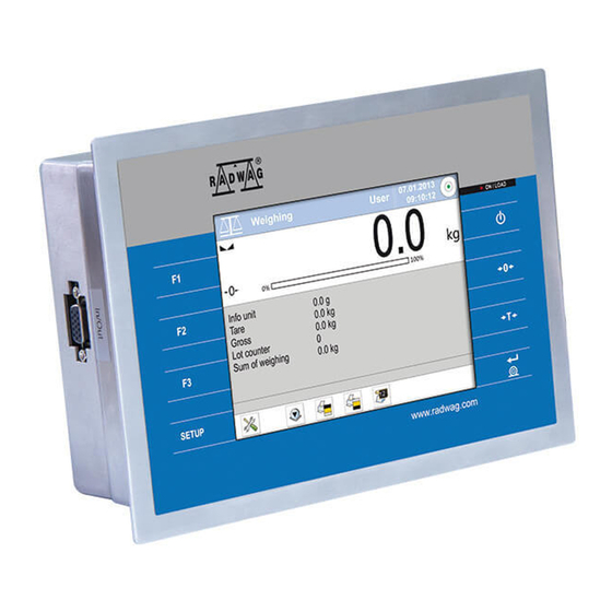
1. INTENDED USE PUE 7.1 weighing indicator is a device intended to be a part of construction of industrial scales based on load cells. Two housing variants are offered: plastic and panel. The terminal has been equipped with 5.7'' colour TFT touch screen facilitating intuitive operation keypad-free. -
Page 6: Maintenance
Daily cleaning routine (removal of small stains): 1. Remove the dirt using cloth dipped in warm water. 2. For best results, add a little bit of dishwashing detergent. 4. MECHANICAL DESIGN 4.1. Dimensions Overall dimensions: PUE 7.1 (plastic housing) -
Page 7: Connectors
Overall dimensions: PUE 7.1 (panel version) 4.2. Connectors 4.2.1. PUE 7.1 Connectors 1 – Ethernet RJ45 connector 1 – power supply socket 2 – RS232 (COM1) connector 2 – I/O, RS232 (COM2) connector 3 – USB connector... -
Page 8: Pue 7.1P Connectors
4.2.2. PUE 7.1P Connectors 1 – Ethernet RJ45 connector 2 – RS232 (COM1) connector 1 – I/O, RS232 (COM2) connector 3 – USB connector 4.2.3. PUE 7.1P Cable Glands 1 – cable gland for the power cord 2 – 1, 2 platform cable gland 3 –... -
Page 9: Inputs / Outputs
4.3. Inputs / Outputs Standard PUE 7.1 indicator is equipped with 4 optoisolated inputs and 4 semiconductor outputs (solid-state relays). The signals are fed through connector. DSUB15/F IN/OUT, RS232 - DSUB15/F connector (female), front: Pin1 – GNDWE Pin2 - OUT1 Pin3 - OUT2 Pin4 –... -
Page 10: Operation Panel
4.4. Operation Panel Keys Press to switch the scale ON/OFF. Press to zero the scale. Press to tare the scale. Press to send the weighing result to a printer or a computer. Press to enter the menu (function button). Programmable key. Programmable key. -
Page 11: Technical Specifications
4.5. Technical Specifications PUE 7.1 PUE 7.1P Housing plastic panel - stainless steel Panel version - IP66/67, Ingress protection IP43 Indicator + panel – IP32 TFT 640x480 5.7” with touch panel Display 10 – 28 VDC/21W Power supply -10 °C ÷ 40 °C... -
Page 12: Home Screen
Mind to keep the key pressed for about 0.7 s. operating system and RADWAG program are loaded, this is signalled with blinking of red ON/LOAD diode. Upon completed start-up, the home screen is displayed automatically. -
Page 13: Top Bar
6.1. Top Bar The top bar displays the following information: Working mode name and symbol. Login entry. Symbol informing that communication with a PC is on. ® Symbol informing that Wi-Fi connection is on. Symbol informing that communication with the E2R SYSTEM is on. Weighing device name. -
Page 14: Function Buttons
6.4. Function Buttons On-screen function buttons are to be found underneath the workspace. You can define on-screen function buttons individually for each working mode. 7. OPERATING THE MENU 7.1. Operation Panel Press to go to the menu. Press to scroll the menu up. Press to scroll the menu down. -
Page 15: Return To Weighing
8. INSTALLER INSTRUCTION The PUE 7.1 indicator can be a base component of a load cell scale. 8.1. 6-Wire Load Cell Connection Connect 6-wire load cell to the main board following the diagram below:... -
Page 16: 4-Wire Load Cell Connection
Radwag A/D converter board Load cell signals NOTES SHIELD See section 8.3 REF+ SENSE + Z8 not soldered REF- SENSE - Z4 not soldered OUTPUT+ OUTPUT- INPUT+ AGND INPUT- 8.2. 4-Wire Load Cell Connection Connect 4-wire load cell to the main board following the diagram below:... -
Page 17: Connecting Load Cell's Cable Shield
8.3. Connecting Load Cell’s Cable Shield Load cell with galvanic Load cell without galvanic connection of the signal connection of the signal cable shield cable shield Scale with an indicator in a plastic do not connect housing - the platform connected with the indicator via load cell's signal cable only. -
Page 18: Colours Of Weighing Platform's Signal Wires
9.1.2. Colours of Weighing Platform's Signal Wires Markings Marking of terminals (solder pads) on RADWAG Colour RADWAG A/D converter boards +INPUT brown -INPUT green AGND +OUTPUT yellow - OUTPUT white SENSE grey +REF - SENSE pink - REF SHIELD yellow green by shield connection guidelines Figure 18. -
Page 19: Global Parameters
(read section 11). Declaring whether the scale is verified Verified or not. Request modules Enabling/disabling pairing of modules pairing connecting with PUE 7.1 indicator. Enabling/disabling modifications „Parts Counting” mode for verified NTEP scales (USA market). 6.25, 12.5, Converter speed Converter rate change. - Page 20 Enabling/disabling additional RS485 Additional RS 485 port for communication with MWMH, communication module MWSH, MWLH, HRP modules. Protection against deleting data from Weighing data storage weighing, average tare period [days] databases, data storage period is given in days. Service Service mode. Submenu containing advanced service Advanced settings settings.
-
Page 21: Factory Parameters
0 100 FLASH memory usage FLASH memory usage [%]. 0 100 RAM usage RAM usage [%]. 10.3. Factory Parameters NAME DEFAULT VALUES DESCRIPTION Metrology Metrology-related settings. Rounding of the last digit and position of 0.001 50 Reading unit: range 1 0.001 a decimal point for weighing range I. -
Page 22: Metrological Data
PUE 7.1, WLY, Selecting scale type, the scale type is Scale type WPY, HRP conditioned by an indicator type. Special name and/or name of RADWAG distributor's device (6 characters maximum). Scale name name entered this parameter replaces the selected “Scale type”... -
Page 23: Factory Adjustment
10.5. Factory Adjustment 10.5.1. External Adjustment Enter < Factory/ Adjustment> submenu and go to < Adjustment> parameter. Unload the platform. Message <Unload the platform> is displayed. Press button. Start mass is determined, message <Start mass determination> is displayed. ... -
Page 24: Linearity Correction
10.6. Linearity Correction 10.6.1. Linearity Determination Determining mass for each step of the linearity and corrections via scale software. Procedure: Enter < Factory/ Linearity> submenu and go to <Determine> parameter. <Mass> dialog box and an on-screen keyboard opens. Unload the platform. ... -
Page 25: Deleting Linearity
determined by gravitational acceleration method, determined by latitude method. 10.8.1. Entering the Gravitational Correction Value The gravitational correction value must be entered with reference to tables prepared by „Radwag Balances and Scales” or calculated using the below formula:... -
Page 26: Gravitational Acceleration Method
Gcor uzy t. kal. If the scale is calibrated at the place of use then gravitational correction value (<g-cor.> parameter) is 1.00000. If the scale is calibrated away from the place of use (longitudinal change) the value of <g-cor.> parameter must be corrected. -
Page 27: Latitude Method
Press button to confirm, the newly calculated gravitational correction value is automatically attributed to <g-cor.> parameter of < Factory / Metrology> submenu. Return to weighing, saving changes. 10.8.3. Latitude Method The method consists in automatic calculation of value of gravitational correction, <g-cor.>, on the basis of: ... -
Page 28: Declaring Verified Scale
- non-verified scale 11. ANNEX A - Communication with Modules Taking Function of an Additional Weighing Platform In order to declare type of a weighing module connecting with the PUE 7.1 indicator go to: < Global> submenu. Weighing module's transmission parameters (baud rate, computer port) and PUE 7.1 indicator's transmission... - Page 29 Refresh * from the associated device. *) - Transmission parameters of PUE 7.1 indicator must be compatible with the associated device. To set transmission parameters of PUE 7.1 go to „SETUP/ Communication” submenu. Set respective parameter values and return to weighing, saving changes.
-
Page 30: Communication With Mw-01 Weighing Module
RS232 or Ethernet interface. Procedure: Connect the MW-01 module to the PUE 7.1 indicator using RS232 or Ethernet cable (conditioned by model), and switch both devices on. Enter global parameters submenu of the PUE 7.1 indicator. - Page 31 In order to set transmission parameters for MW-01 weighing module it is necessary to put a jumper onto the module's main board: Procedure: Make sure that communication between the PUE 7.1 and the MW-01 is established, and enter factory parameters submenu of the PUE 7.1 indicator.
- Page 32 (read section 11.2.2). Make sure that communication between the PUE 7.1 and the MW-01 is established, and enter factory parameters submenu of the PUE 7.1 indicator.
-
Page 33: Communication With Hrp Weighing Module
11.3. Communication with HRP Weighing Module Connection between PUE 7.1 indicator and HRP weighing module requires: establishing communication between the PUE 7.1 and the HRP module, editing and record of transmission parameters, and all factory parameters, to the HRP module memory, using the PUE 7.1 indicator. - Page 34 RS232, RS485 or Ethernet interface. Procedure: Connect the HRP module to the PUE 7.1 indicator using a dedicated RS232, RS485 or Ethernet cable (list of connection cables is to be found in service manual of the HRP module).
- Page 35 SW1 switch on the main board of the module. Follow HRP service manual. Make sure that communication between the PUE 7.1 and the HRP is established, enter factory parameters submenu of the PUE 7.1 indicator.
- Page 36 Go to a modified submenu of the weighing platform, list containing factory parameter values read from the HRP weighing module is displayed: NAME VALUES DESCRIPTION Metrology Metrology-related settings. Rounding of the last digit and position of a 0.001 50 Reading unit: range 1 decimal point for weighing range I.
- Page 37 Temperature compensation procedure carried Internal correction of out with the use of an internal adjustment temperature weight. Temperature compensation procedure carried External correction of out with the use of an external adjustment temperature weight. Start mass Start mass value (in divisions). Adjustment factor Adjustment factor.
- Page 38 Export Parameter export. Group parameters communication Pue Y: Communication between PUE 7.1 indicator and HRP module (read section 11.3.1). Group of parameters enabling modification MW-MH: Communication of transmission parameters for HRP module using PUE 7.1 indicator (read section 11.3.2). Set default Restoring default HRP module settings.
-
Page 39: Diagrams Of Connection Cables
11.3.4. Paring of HRP Platform with PUE 7.1 Indicator Function requesting the necessity to pair HRP platform with PUE 7.1 indicator. Procedure: Enter <Info / Paired modules / Pair modules> submenu. The HRP platform is automatically paired with the PUE 7.1 indicator, message <Modules paired>... - Page 40 Scale - printer cable (CITIZEN, EPSON) I/O cable „Scale-Ethernet” cable is a standard network cable terminated with RJ45 connectors on both ends.
Need help?
Do you have a question about the PUE 7.1 and is the answer not in the manual?
Questions and answers