RADWAG PUE C315 User Manual
Hide thumbs
Also See for PUE C315:
- User manual (44 pages) ,
- Quick start manual (13 pages) ,
- Startup manual (13 pages)
Table of Contents
Advertisement
Quick Links
Advertisement
Table of Contents

Related Manuals for RADWAG PUE C315


Summary of Contents for RADWAG PUE C315
- Page 2 APRIL 2021...
-
Page 3: Table Of Contents
CONTENTS 1. INTENDED USE ..............................5 2. WARRANTY CONDITIONS ..........................5 3. MAINTENANCE ACTIVITIES ..........................5 3.1. Cleaning ABS Components......................... 5 3.2. Cleaning Stainless Steel Components ......................6 4. DESIGN ................................6 4.1. Dimensions ..............................6 4.2. Connectors Arrangement ..........................7 4.3. - Page 4 PRECAUTIONS Prior to installation, use or maintenance activities, carefully read this user manual and follow the provided guidelines. Prior to the first use, carefully read this user manual. Use the device only as intended. Protect the indicator against considerable temperature variation, solar and UV radiation, substances causing chemical reactions.
-
Page 5: Intended Use
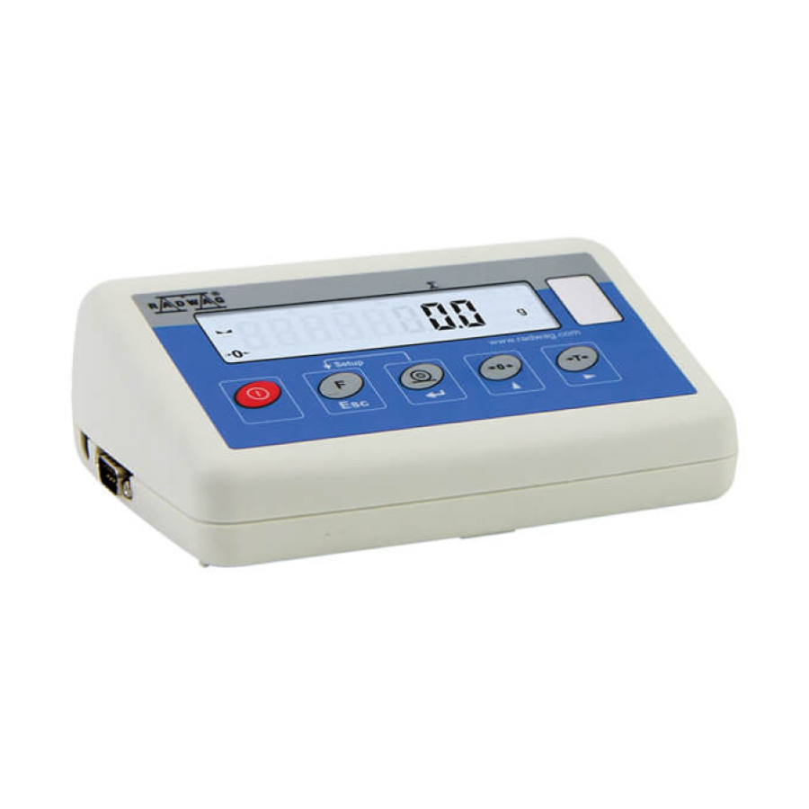
1. INTENDED USE PUE C315 weighing indicator is a device intended to make industrial scales operating on the basis of load cells. The indicator is equipped with an internal battery, this allows its operation in places where there is no access to the mains. -
Page 6: Cleaning Stainless Steel Components
Always remove the dirt using microfiber cloth to avoid damage of protective coating. In case of a daily maintenance: 1. Remove the dirt using cloth dipped in warm water. 2. For best results, add a little bit of dishwashing detergent. 4. DESIGN 4.1. Dimensions Dimensions of PUE C315... -
Page 7: Connectors Arrangement
4.2. Connectors Arrangement 1 – power supply socket 3 – weighing platform cable inlet 2 – RS232 (1) connector 4 – RS232 (2) connector * *) - option. 4.3. Pins Overview Pin2 – RxD Pin3 – TxD RS232 (1) connector, DB9/M (male) Pin4 –... -
Page 8: Technical Specifications
Keys: Press to switch the weighing device on/off – hold the key for about 1 second. Function key, press to change the working mode. Press to send the weighing result to a printer or computer. Press to zero the scale. Press to tare the scale. -
Page 9: Indicator Installation
Standard interfaces RS232 (1), Wireless communication Optional interfaces RS232 (2) 5. INDICATOR INSTALLATION 5.1. Unpacking and Installation A. Take the indicator out of the packaging. B. Connect the indicator and the platform and place the set on a flat and even surface. -
Page 10: Battery Charge Status Check
Meaning pictogram display mode No pictogram Battery charged. Regular scale operation. Too low battery charge (the scale is about to shut Pictogram displayed continuously down). Charge the battery immediately. Blinking pictogram, blink frequency: Battery charge in progress. The device is connected ca. -
Page 11: Operating The Menu
Close the lid. 6. OPERATING THE MENU In order to navigate the program menu use the operation panel. Press to enter the main menu. Press to enter tare manually. Press to enter tare from tare database. Press to change value by 1 digit up. Press to scroll the menu up. -
Page 12: Installer Instruction
7. INSTALLER INSTRUCTION The PUE C315 indicator serves as basis of load cell scales. 7.1. Connecting 6-Wire Load Cell Connect 6-wire load cell to the main board following the diagram below: 6-wire load cell connection RADWAG BOARD SIGNALS LOAD CELL SIGNALS... -
Page 13: Connecting 4-Wire Load Cell
7.2. Connecting 4-Wire Load Cell Connect 4-wire load cell to the main board following the diagram below: Connecting 4-wire load cell RADWAG BOARD SIGNALS LOAD CELL SIGNALS NOTES SHILED refer to section 7.3 REF+ SENSE+ JP5 soldered REF- SENSE- JP6 soldered... -
Page 14: Connecting Load Cell's Cable Shield
7.3. Connecting Load Cell’s Cable Shield Load cell with galvanic Load cell without galvanic connection of the signal connection of the signal cable shield. cable shield. Balance with indicator in ABS housing Do NOT connect connected with platform via load cell signal cable. -
Page 15: Factory Parameters List
Weighing device type: 1 - WLC/A2; 2 - WLC/F, WLC/C2, 4 – WTC, 6 – Medical scale, 7 - Medical scale 0.1.3. 1, 2, 4, 6, 7, 8, 12 (BMI disabled), 8 – PUE C315; 12 – WLC/C/2. 0.1.4. Gcor 0.9 - 1.1 Gravity correction factor. - Page 16 0.0001, 0.0002, 0.0005, 0.001, 0.002, 0.005, 0.01, 0.2.5. Range 2 reading unit. 0.02, 0.05, 0.1, 0.2, 0.5, 1, 2, 5, 10, 20, 50 no, 0.001, 0.01, 0.1, 1, 2, Range 2 verification unit; no - non- 0.2.6. verified balance/scale. 0.2.7. Maximum range + overload.
-
Page 17: Defining The Device
Internal adjustment weight weighing 0.3.8. procedure. Internal weight relocation, up-down 0.3.9. direction. Display current temperature, 0.3.A in [C]. 0.4. LinE Linearity 0.4.1. Entering linearity correction points. 0.4.2. Deleting linearity. 0.4.3. Entering correction values for linearity. 0.5. Boot Bootloader 0.6. dFLt Default settings. -
Page 18: Factory Adjustment
While defining balance/scale type, additional parameters are set automatically. These are among many battery type, internal adjustment accessibility, additional modules and communication interfaces accessibility. 8.4. Factory adjustment 8.4.1. External Adjustment Process Enter factory setup submenu: <P0.FAct / 0.3.CAL>. Enter <0.3.1.CLE> function, text <UnLoAd> is displayed. ... -
Page 19: Correction Of Start Mass Expressed In Converter's Divisions
8.4.3. Correction of Start Mass Expressed in Converter's Divisions Enter factory setup submenu: <P0.FAct / 0.3.CAL>. Enter <0.3.4.Stu> submenu, value of start mass expressed in converter's divisions is displayed. Correct the value, to do it use operation panel, next press key to confirm changes. -
Page 20: Corrections
It allows to carry out correct balance/scale calibration away from the point of subsequent use. The gravity correction value must be entered with reference to tables prepared by „Radwag Balances and Scales” or calculated using the below formula:... -
Page 21: Diagrams Of Connection Cables
Gcor uzy t. kal. Correction value ranges between 0.90000 ÷ 1.99999. If the balance is calibrated in the place of use then the value of gravitational coefficient, <0.1.4.Gcr> parameter, must be 1.00000. If the weighing instrument is calibrated away from the place of use (longitudinal change) the value must be corrected.
Need help?
Do you have a question about the PUE C315 and is the answer not in the manual?
Questions and answers