RADWAG PUE C32 User Manual
Hide thumbs
Also See for PUE C32:
- User manual (98 pages) ,
- User manual (106 pages) ,
- Quick start manual (13 pages)
Table of Contents
Advertisement
Quick Links
Advertisement
Table of Contents

Related Manuals for RADWAG PUE C32


Summary of Contents for RADWAG PUE C32
- Page 2 AUGUST 2020...
- Page 3 Protect the indicator against considerable temperature variation, solar and UV radiation, substances causing chemical reactions. The PUE C32 indicator must not be operated in hazardous areas endangered with explosion of gases, and in dusty environments. In case of damage, immediately unplug the device from the mains.
-
Page 4: Table Of Contents
Contents 1. INTENDED USE ..............................5 2. WARRANTY CONDITIONS ..........................5 3. MAINTENANCE ACTIVITIES ..........................5 3.1. Cleaning ABS Components......................... 6 3.2. Cleaning Stainless Steel Components ......................6 4. MECHANICAL DESIGN ............................. 6 4.1. Dimensions ..............................6 4.2. Connectors Arrangement ..........................7 4.3. -
Page 5: Intended Use
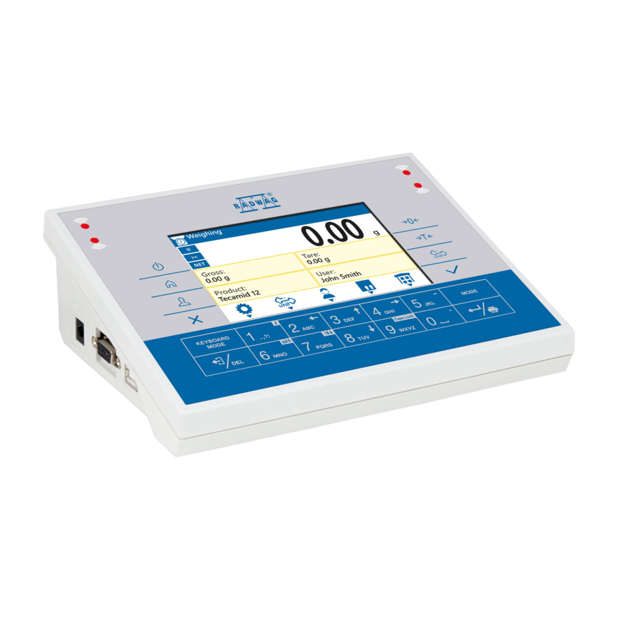
1. INTENDED USE The PUE C32 weighing indicator is a part of construction of industrial scales operating on the basis of load cells. The indicator features an ABS plastic housing and a 5'' colour graphic display ensuring perfect readability. It is operated using 22-key membrane keypad equipped with programmable function keys. -
Page 6: Cleaning Abs Components
Always remove the dirt using microfiber cloth to avoid damage of protective coating. Daily cleaning routine (removal of small stains): 1. Remove the dirt using cloth dipped in warm water. 2. For best results, add a little bit of dishwashing detergent. 4. MECHANICAL DESIGN 4.1. Dimensions PUE C32 overall dimensions... -
Page 7: Connectors Arrangement
RS232 - DSUB15/F connector (female), front: Pin8 - TxD2 Pin9 - 5VDC Pin10 - GND Pin13 - RxD2 4.4. Inputs / Outputs Standard PUE C32 indicator is equipped with 4 optoisolated inputs and 4 semiconductor outputs (solid-state relays). The signals are fed through connector. DSUB15/F... -
Page 8: Technical Specifications
I/O, RS232 DSUB15/F (female) connector, front: Pin1 – GNDWE Pin2 - OUT1 Pin3 - OUT2 Pin4 – COMM Pin6 - IN4 Pin7 - IN3 Pin11 - IN2 Pin12 - IN1 Pin14 - OUT4 Pin15 - OUT3 4.4.1. Technical Specifications Output parameters Output quantity Output type Solid-state relay... -
Page 9: Operation Panel
4.5. Operation Panel Keys Press to switch the device on / off. Press to enter the main menu. Press to log in. Press to cancel the message. Press to zero the scale. Press to tare the scale. Press to change the weighing unit. Press to confirm the message. -
Page 10: Technical Specifications
Programmable key assigned to an on-screen button. key – long press to get scale info. Programmable key assigned to an on-screen button. Programmable key assigned to an on-screen button. Programmable key assigned to an on-screen button. Programmable key assigned to an on-screen button. 4.6. -
Page 11: Start-Up
5.2. Start-Up The indicator can be connected to the mains only with a power supply that comes standard with the particular model. Nominal voltage of the power supply (specified on the power supply data plate) has to be compatible with the mains nominal voltage. -
Page 12: Home Screen
The home screen features 4 sections: a top bar, a weighing result window, workspace, pictograms. Home screen view: Detailed instruction on how to configure the home screen is to be found in „PUE C32 Indicator Software Manual”. 6.1. Top Bar The top bar displays the following information: Working mode name and symbol. -
Page 13: Weighing Result Window
6.2. Weighing Result Window Weighing result window provides all weighing-related data. 6.3. Workspace The workspace is to be found underneath the weighing result window. The workspace comprises 4 programmable widgets. Each working mode features a default home screen widget set. You can customize the screen. 6.4. -
Page 14: Menu Keys
Menu view 7.2. Menu Keys Press to enter the main menu. Press to go to the home screen. Press to go back. Press to discard entering parameter modifications. Press to go back. Press to delete a character when editing numeric and text values. Press to change keyboard mode when editing numeric and text values. -
Page 15: Entering Numbers / Text
7.3. Entering Numbers / Text The software features two different edit boxes: numerical box (for entering part mass values, tare values, etc.). text box (for entering printout template, universal variable value, etc.). Button functions change depending on the edit box type. 7.3.1. -
Page 16: Text Box
Press to enter digit 4. Press to enter digit 5. Press to enter „-” (minus), hold the key for a few seconds. Press to enter digit 6. Press to enter digit 7. Press to enter digit 8. Press to enter digit 9. Press to enter digit 0. - Page 17 Where: Upper-case character mode. To change keyboard working mode press key. Keyboard working mode options: - upper-case character mode, - lower- case character mode, - digit mode, - arrow keys operation, - bottom bar operation. Press to save the project to *.lb file on a USB flash drive. Press to read the project saved to *.lb file on a USB flash drive.
-
Page 18: Diacritical Sign Table
Press to exit, the edit box content remains unmodified. Press to confirm the modifications. Press to change keyboard working mode. 7.3.3. Diacritical Sign Table In order to activate the diacritical sign table while editing a text box, it is necessary to press and hold down key. -
Page 19: Return To Weighing
press key, the home screen is displayed immediately. 8. INSTALLER INSTRUCTION The PUE C32 indicator serves as basis of load cell scales. 8.1. Connecting 6-Wire Load Cell Connect 6-wire load cell to the main board following the diagram below:... -
Page 20: Connecting 4-Wire Load Cell
On RADWAG board Load cell signal Notes SHIELD See section 9.3 REF+ SENSE + JP3 not soldered REF- SENSE - JP4 not soldered OUTPUT+ OUTPUT- INPUT+ AGND INPUT- 8.2. Connecting 4-Wire Load Cell Connect 4-wire load cell to the main board following the diagram below:... -
Page 21: Load Cell Shield Connection
On RADWAG board Load cell signal Notes SHIELD See section 9.3 REF+ JP3 soldered REF- JP4 soldered OUTPUT+ OUTPUT- INPUT+ AGND INPUT- 8.3. Load Cell Shield Connection Load cell with galvanically Load cell w/o galvanically connected shield of the connected shield signal cable. -
Page 22: Global Parameters
Enabling disabling display Activation metrological data in a top bar of the home screen. Setting scale type. For PUE C32 value PUE C32, Scale type PUE C32 only weighing indicator name C32, WLX displayed, metrological data is not. -
Page 23: Factory Parameters
Service Service settings menu. Preview of operation parameters and Battery diagnostics battery charge-up. RTC adjustment RTC synchronisation. Total operation time, time format: Operation time "D: xx H: yy" (D - day, H - hour). Processor number, necessary CPU Id generate code unlocking Wi-Fi module. Restore default Restoring default settings (factory and operator settings... - Page 24 Autozero time [s]: Predefined - value Predefined, 0, 0.2, taken from program-implemented 0.4, 0.6, 0.8, 1, 2, 3, Autozero time Predefined 4, 5, 6, 7, 8, 9, 10, tables; 020 - value entered directly 15, 20. by a user. Stability range [d]: Predefined - value Predefined, 0.1, 0.2, taken from...
-
Page 25: Return To Weighing
9.4. Return to Weighing Introduced modifications are automatically recorded upon return to the home screen. To return to the home screen: press key repeatedly, keep pressing the key until you see the home screen, press key, the home screen is displayed immediately. 9.5. -
Page 26: Corrections
Procedure: Enter <Factory/Section linearity> submenu and select <Determine> parameter. Message <Continue?> is displayed. Press key to confirm. <Mass> edit box is displayed. Unload the weighing pan. Enter the required mass value (the first linearity correction point) and press key to confirm. -
Page 27: Deleting Linearity
It allows to carry out correct scale calibration/adjustment away from the point of subsequent use. The gravity correction value must be entered with reference to tables prepared by „Radwag Balances and Scales” or calculated using the below formula: Gcor ... - Page 28 Scale - printer cable (ZEBRA) Scale - printer cable (EPSON) I/O cable „Scale-Ethernet” cable is a standard network cable terminated with RJ45 connectors on both ends.
Need help?
Do you have a question about the PUE C32 and is the answer not in the manual?
Questions and answers